
2. COMMAND SET
2.1: Copley ASCII Message Format
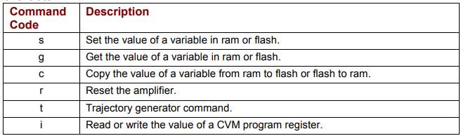
The syntax of a Copley ASCII message is:
[<optional node ID>] <command code> [<command specific parameters>...] <CR>
where:
•[<optional node ID>] is the CAN node address of an amplifier in a multi-drop network. Range is 0 127. The node ID is followed by a single space.
• <command code> is the single-letter code for one of the Copley ASCII commands described below. It is followed by a single space, or, in the case of the Reset command, a carriage return character.
• <command specific parameters> tell the command what to act on and how. If more than one parameter is required, they should be separated by spaces.
• <cr> is a carriage return character that ends the command line.
For multi-axis amplifiers, see Copley ASCII Message Format for Multi-Axis Drives (p. 19).
2.2: Set (s) Command
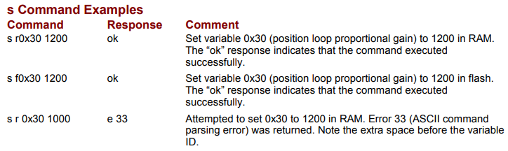
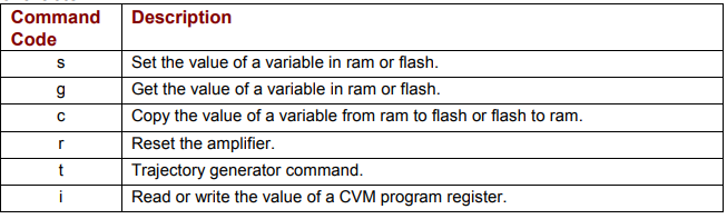
The s command is used to set values of writeable amplifier variables.
The syntax of the s command is:
[ optional node ID] s <memory bank><variable ID> <value>...]<CR>
where:
• [optional node ID] is the CAN node address of an amplifier in a multi-drop network.
Range is 0-127. It is followed by a single space.
• s is the Set command code. It is followed by a single space.
• <memory bank> identifies which memory bank to set the variable in.
f = flash memory
r = RAM memory
• <variable ID> identifies the variable to set. Variable ID format can be decimal or hexadecimal.
• <value> is the new value(s) to be set in the variable. Value can be sent in integer or hexadecimal format. If multiple values are required, they are separated by spaces.
<CR> is a carriage return character which immediately follows the last value.
The amplifier responds to the s command with:
• ok<CR> if the command is accepted.
• e <error #><CR> if the command was not accepted. See Error Codes
2.3: Get (g) Command
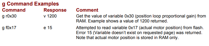
The g command is used to get the values of amplifier variables.
The syntax of the g command is:
[ optional node ID] g <memory bank><variable ID><CR>
where:
• [optional node ID] is the CAN node address of an amplifier in a multi-drop network.
Range is 0-127. It is followed by a single space.
• sg is the SetGet command code. It is followed by a single space.
• <memory bank> identifies which memory bank to setget the variable in.from.
f = flash memory
r = RAM memory
• <variable ID> identifies the variable to set.get. Variable ID format can be decimal or hexadecimal.
• <value> is the new value(s) to be set in the variable. Value can be sent in integer orhexadecimal format. If multiple values are required, they are separated by spaces.
<CR> is a carriage return character which immediately follows the lastvariable value.ID.
The amplifier responds to the sGet command with:
• okv [value]<CR> ifwhere value equals the commandcontents isof accepted.the variable. If the variable contains
multiple values, they will separated by spaces.
• e <error #><CR>(CR) if the command was not accepted. See Error Codes (p.
2.4: Copy (c) Command
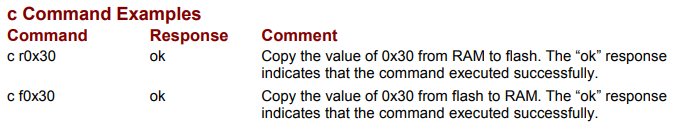
The c command is used to copy the value of a variable from one memory bank to another (RAM to flash or flash to RAM).
The syntax of the c command is:
[ optional node ID] c <memory bank><variable ID><CR>
where:
• [optional node ID] is the CAN node address of an amplifier in a multi-drop network.
Range is 0-127. It is followed by a single space.
• c is the Copy command code. It is followed by a single space.
• <memory bank> identifies which memory bank is the source.
f = flash memory
r = RAM memory
• <variable ID> identifies the variable to copy. Variable ID format can be decimal or
hexadecimal.
• <CR> is a carriage return character which immediately follows the variable ID.
The amplifier responds to the c command with:
• ok<CR> if the command is accepted.
• e <error #>(CR) if the command was not accepted. See Error Codes
2.5: Reset (r) Amplifier Command
The r command is used to immediately reset the amplifier. The command requires no additional parameters. The amplifier baud rate is set to 9600 when the amplifier restarts.
The syntax of the Reset command is:
[optional node ID] r<CR>
where:
• [optional node ID] is the CAN node address of an amplifier in a multi-drop network.
Range is 0-127. It is followed by a single space.
• r is the Reset command code.
• <CR> is a carriage return character which immediately follows the command code.
The amplifier does not respond to the r command with an ASCII message.

NOTE: if a reset command is issued to an amplifier on a multi-drop network, error code 32, “CAN Network communications failure,” will be received. This is because the amplifier reset before responding to the gateway amplifier. This error can be safely ignored in this circumstance
2.6: Trajectory (t) Generator Command
The t command controls the trajectory generator. It can initiate a new move, update a move in progress, or start a home sequence. It can also abort a move.
The syntax of the t command is:
[ optional node ID] t <sub-command><CR>
where:
• [optional node ID] is the CAN node address of an amplifier in a multi-drop network.
Range is 0-127. It is followed by a single space.
• t is the Trajectory command code. It is followed by a single space.
• <sub-command>
0 = Abort move
1 = Initiate/update move
2 = Initiate home sequence
• <CR> is a carriage return character which immediately follows the sub-command. The amplifier responds to the t command with:
• ok<CR> if the command is accepted. An “ok” response only indicates the command was accepted by the amplifier. Monitor the trajectory status register to verify that motion has actually been initiated.
• e <error #>(CR) if the command was not accepted. See Error Codes

2.7: Register (i) Read and Write Command
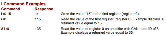
The Register command (i) is used to read and write the CVM program’s 32 internal registers.
The syntax of the i command is:
[ optional node ID] i <r#> [<value>]<CR>
where:
• [optional node ID] is the CAN node address of an amplifier in a multi-drop network.
Range is 0-127. It is followed by a single space.
• i is the Register command code. It is followed by a single space.
• <r#> identifies which register is being accessed.
# = Equals the number of the register (0 – 31).
• <value> is the new value to be written into the register. If <value> is omitted from the command then the contents of the register will be returned. Value can be sent in integer or hexadecimal format.
• <CR> is a carriage return character which immediately follows the register number or the value.
The amplifier responds to the i command with:
• ok<CR> if the command is accepted and the value is written to the register.
• r [value]<CR> where value equals the contents of the register.
• e <error #>(CR) if the command was not accepted. See Error Codes
2.8: Copley ASCII Message Format for Multi-Axis Drives
Some Copley Controls amplifiers can drive up to three axes of motion. When sending an ASCII command to an amplifier that is driving more than one axis, it is necessary to specify the axis as described below:
[<optional node ID>].<axis letter> <command code> [<command specific parameters>...] <CR>
where:
• [<optional node ID> ] is the CAN node address of an amplifier in a multi-drop network.
Range is 0-127. The node ID is followed by a period and the axis letter.
• .<axis letter> specifies the axis (a, b, or c). The axis letter is preceded by a period and followed by a space.
• <command code> is the single-letter code for one of the Copley ASCII commands described below. It is followed by a single space, or, in the case of the Reset command, a carriage return character.
• <command specific parameters> tell the command what to act on and how. If more than one parameter is required, they should be separated by spaces.
• <cr> is a carriage return character that ends the command line
