
1. INTRODUCTION
This chapter describes the basic functions and operational theory of CME 2. Topics
include:
Host Computer Requirements
Amplifier Commissioning Software
Servo Operating Modes and Control Loops
1.1: Host Computer Requirements
1.1.1: Computer and Operating System
Minimal hardware requirements:
• CPU: 400 MHZ.
• RAM: 128 MB.
Operating Systems Supported: Windows NT, 2000, XP.
Vista users see Special Notes for Vista Users
1.1.2: Special Notes for Vista Users
Windows Vista is supported in this version of CME 2.
Note that when the installer starts, a message will be displayed stating that an unidentified program is trying to access the computer. Click the button to allow the installer to continue, and CME 2 will be installed properly.
On previous versions of Windows, the user data for CME 2 (like ccx, ccm, files, etc.) were stored in C:\Program Files\Copley Motion\CME 2. Because of Windows Vista security, the CME 2 user files are stored on Vista systems in C:\Users\Public\Public Documents\Copley Motion\CME 2.
1.1.3: Software
Copley Controls CME 2 software, Version 5.2 or higher.
1.1.4: Serial Communications
For each PC-to-amplifier connection via serial port:
• One standard RS-232 serial port or a USB port with a USB-to-RS-232 adapter.
• One serial communication cable. See amplifier data sheet for part numbers.
1.1.5: CAN Communications
(Xenus, Accelnet, and Stepnet only.)
• One Copley Controls CAN PCI network card (part number CAN-PCI-02). CME 2 also supports CAN network cards made by these manufacturers: KVaser, Vector, and National Instruments.
• One PC-to-amplifier CANopen network cable. See amplifier data sheet for part numbers.
See the amplifier data sheet for CAN network wiring instructions.
1.2: Amplifier Commissioning Software
Copley Controls CME 2 software allows fast and easy commissioning of Copley Controls amplifiers. It provides access to all amplifier configuration controls. It supports all Copley Controls amplifiers, including Copley’s CANopen amplifier lines and stepper amplifiers.
CME 2 communicates with amplifiers via RS-232 or CAN connections. On Xenus, Accelnet, and Stepnet amplifiers, the multi-drop feature allows CME 2 to use a single RS232 serial connection to one amplifier as a gateway to other amplifiers linked together by CAN bus or DeviceNet connections.
Motor data can be saved as .ccm files. Amplifier data is saved as .ccx files that contain all amplifier settings plus motor data. This makes it possible to quickly set up amplifiers by copying configurations from one amplifier to another.
CME 2 also provides access to Copley Virtual Machine (CVM), a program that is set up in CME 2 and downloaded to the amplifier to provide on-board control. When a CVM program is running, the amplifier receives its input commands from the CVM program. For more information, see the Copley Indexer 2 Program User’s Guide.
NOTE: The feature descriptions in this manual may not apply to all Copley Controls amplifiers under all configurations. Significant differences between amplifier models are noted. See the relevant hardware manual or data sheet for more information
1.3: Servo Operating Modes and Control Loops
Copley Controls amplifiers use up to three nested control loops - current, velocity, and position - to control a motor in three associated operating modes. (Stepper amplifiers operated in stepper mode function as traditional open position loop stepper drives.)
Control Loops Model
In position mode, the amplifier uses all three loops. As shown in the typical system illustrated below, the position loop drives the nested velocity loop, which drives the nested current loop.
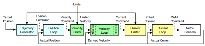
In velocity mode, the velocity loop drives the current loop. In current mode, the current loop is driven directly by external or internal current commands.
Basic Attributes of All Servo Control Loops
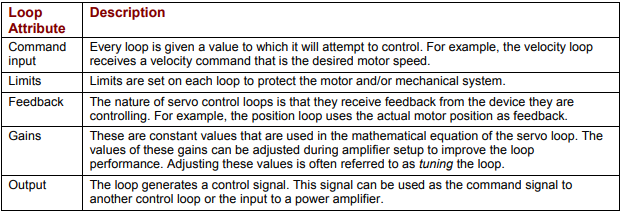
These loops share several common attributes:
For more information on using CME 2 to set up and tune control loops, see Control Loops