
10. MOTOR PHASING
This chapter shows how to phase the motor using the Auto Phase or Manual Phase tool. Perform the basic steps outlined below. Details follow in the chapter.
Use the procedure described in this chapter to Phase Motor with Auto Phase
OR
Use the procedure described in this chapter to Phase Motor Manually
10.1: Phase Motor with Auto Phase
Choose the appropriate procedure:
Auto Phase Example: Servo Amplifier
Auto Phase Example: Stepper Amplifier, No Encoder
Auto Phase Example: Stepper Amplifier with Encoder, in Stepper Mode
Auto Phase Example: Stepper Amplifier with Encoder, in Servo Mode
NOTE: The examples in this chapter show particular amplifier operating modes and motor feedback configurations. Some screens and choices may vary from those described here.
10.1.1: Auto Phase Example: Servo Amplifier
Perform the following steps to Auto Phase a servo amplifier.
NOTE: The following steps show Auto Phase with a brushless rotary motor, digital Halls, and an incremental quadrature encoder. Screens vary for other configurations.
1 Verify that the Enable Input is not activated and that HV or AC power is applied.
2 Click Auto Phase to open the Auto Phase Motor Direction Setup screen.
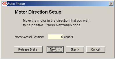
3 Move the motor in the direction to be considered positive OR if you cannot move the motor, click Skip (you will confirm motor direction later).
NOTE: If an output is configured as a brake you can temporarily release the brake by holding down the Release Brake button. The brake will be reactivated when you release the button.
4 Click Next to open the Auto Phase Motor Wiring Setup screen:
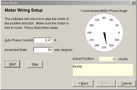
5 Activate the Enable Input.
6 Click Start to begin the motor wiring setup. The message area displays messages: Configuring Initial Settings, Microstepping, Test Complete, Motor Wiring has been configured.
During microstepping, a current vector is applied to the motor windings and microstepped through an electrical cycle at a set rate, causing the motor to move.
If you chose to Skip the motor direction setup step, Auto Phase will prompt for confirmation of correct motor direction.
If the step fails see Motor wiring setup problems
NOTE: If incorrect values were entered for inductance and resistance, the calculated
Cp and Ci values may produce current loop oscillation, evidenced by an audible high frequency squeal during auto phasing.
7 Click Next to open the Auto Phase Phase Count Test screen.
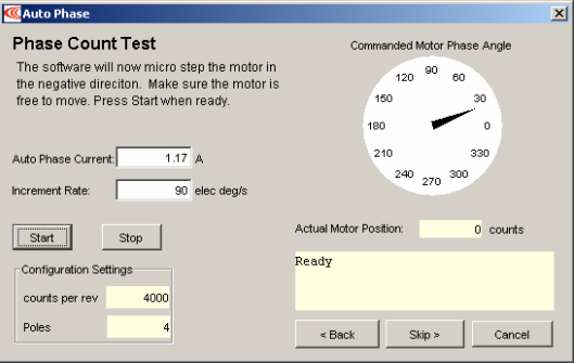
8 Click Start to begin the Phase Count Test. Observe status messages. See the prompt:
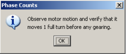
9 When you are ready to observe motion, click OK. See the prompt:
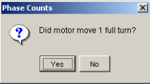
10 If motor did not turn 1 full turn, click No and see Phase count test problems (p. 85).
If motor turned 1 full turn, click Yes.
The message area displays progress and completion messages.
11 For a resolver (–R) version of a Copley Controls amplifier, skip to Step 13 (p. 79).
For a non-resolver amplifier, click Next to open the Hall Wiring Setup screen.