
10. MOTOR PHASING
This chapter shows how to phase the motor using the Auto Phase or Manual Phase tool. Perform the basic steps outlined below. Details follow in the chapter.
Use the procedure described in this chapter to Phase Motor with Auto Phase
OR
Use the procedure described in this chapter to Phase Motor Manually
10.1: Phase Motor with Auto Phase
Choose the appropriate procedure:
Auto Phase Example: Servo Amplifier
Auto Phase Example: Stepper Amplifier, No Encoder
Auto Phase Example: Stepper Amplifier with Encoder, in Stepper Mode
Auto Phase Example: Stepper Amplifier with Encoder, in Servo Mode
NOTE: The examples in this chapter show particular amplifier operating modes and motor feedback configurations. Some screens and choices may vary from those described here.
10.1.1: Auto Phase Example: Servo Amplifier
Perform the following steps to Auto Phase a servo amplifier.
NOTE: The following steps show Auto Phase with a brushless rotary motor, digital Halls, and an incremental quadrature encoder. Screens vary for other configurations.
1 Verify that the Enable Input is not activated and that HV or AC power is applied.
2 Click Auto Phase to open the Auto Phase Motor Direction Setup screen.
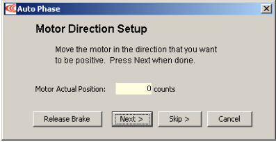
3 Move the motor in the direction to be considered positive OR if you cannot move the motor, click Skip (you will confirm motor direction later).
NOTE: If an output is configured as a brake you can temporarily release the brake by holding down the Release Brake button. The brake will be reactivated when you release the button.
4 Click Next to open the Auto Phase Motor Wiring Setup screen:
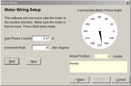
5 Activate the Enable Input.
6 Click Start to begin the motor wiring setup. The message area displays messages: Configuring Initial Settings, Microstepping, Test Complete, Motor Wiring has been configured.
During microstepping, a current vector is applied to the motor windings and microstepped through an electrical cycle at a set rate, causing the motor to move.
If you chose to Skip the motor direction setup step, Auto Phase will prompt for confirmation of correct motor direction.
If the step fails see Motor wiring setup problems
NOTE: If incorrect values were entered for inductance and resistance, the calculated
Cp and Ci values may produce current loop oscillation, evidenced by an audible high frequency squeal during auto phasing.
7 Click Next to open the Auto Phase Phase Count Test screen.
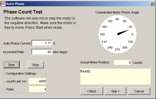
8 Click Start to begin the Phase Count Test. Observe status messages. See the prompt:
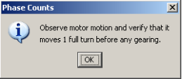
9 When you are ready to observe motion, click OK. See the prompt:
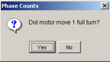
10 If motor did not turn 1 full turn, click No and see Phase count test problemsproblems. (p. 85).
If motor turned 1 full turn, click Yes.
The message area displays progress and completion messages.
11 For a resolver (–R) version of a Copley Controls amplifier, skip to Step 1313. (p. 79).
For a non-resolver amplifier, click Next to open the Hall Wiring Setup screen.
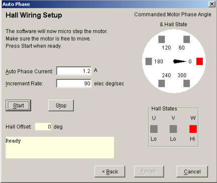
12 Click Start to begin the Halls wiring setup. The message area displays the messages: Microstepping. Test Complete. Motor has been properly phased.
During microstepping, a current vector is applied to the motor windings and microstepped through an electrical cycle at a set rate, causing the motor to move. As the motor moves the Hall lines are decoded for proper commutation.
If the step fails, see Halls wiring setup problems
13 For a resolver (-R) version of a Copley Controls amplifier, click Next to open the Resolver Phase Angle Setup screen.
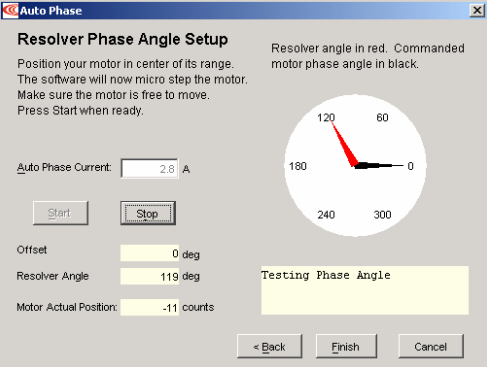
14 Click Start to start the resolver phase angle setup. The message area displays status messages.
15 Click Finish to close the screen and save values to flash memory OR to close the screen without saving changes, click Cancel.
16 If the Auto Phase algorithm does not produce desired results, try adjusting the Auto Phase Current and Increment Rate values, using the guidelines in Guidelines for Choosing Auto Phase Current and Increment Rate Values
17 If desired results are not obtained, or to confirm results, proceed to Phase Motor Manually
10.1.2: Auto Phase Example: Stepper Amplifier, No Encoder
1 Verify that the Enable Input is not activated and that HV power is applied.
2 Click Auto Phase to open the Auto Phase Motor Direction Setup screen.
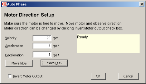
3 Hold down Move POS to move the motor in the direction considered positive, and observe the direction of movement. If the motor does not move see Motor wiring setup problems
4 If the motor moved opposite the direction that you wish to program as positive, click Invert Motor Output.
5 Click OK to save the direction setting.
10.1.3: Auto Phase Example: Stepper Amplifier with Encoder, in Stepper Mode
1 Verify that the Enable Input is not activated and that HV power is applied.
2  Click Auto Phase to open the Auto Phase Motor Direction Setup screen.
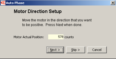
3 Move the motor in the direction you wish to be considered positive.
4 Activate the Enable Input.
5 Click Next to open the Auto Phase Motor Wiring Setup screen.
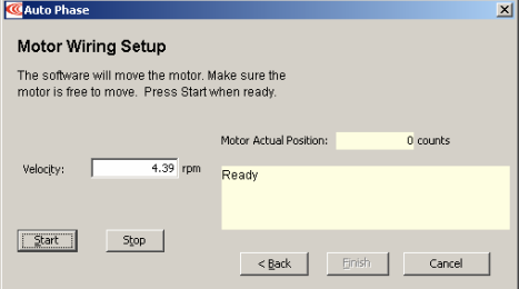
6 Click Start to begin motor wiring setup with default values. After successful motor wiring setup, the message “Test Complete” appears.
7 Click Finish to close the screen and save values to flash memory.
10.1.4: Auto Phase Example: Stepper Amplifier with Encoder, in Servo Mode
1 Verify that the Enable Input is not activated and that HV power is applied.
2  Click Auto Phase to open the Auto Phase Motor Direction Setup screen.
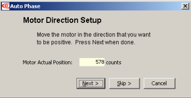
3 Move the motor in the direction you wish to be considered positive.
4 Activate the Enable Input.
5 Click Next to open the Auto Phase Motor Wiring Setup screen.
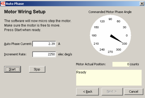
6 Click Start to begin the motor wiring setup.
The message area displays messages: Configuring Initial Settings, Microstepping, Test Complete, Motor Wiring has been configured.
During microstepping, a current vector is applied to the motor windings and microstepped through an electrical cycle at a set rate, causing the motor to move.
If you chose to Skip the motor direction setup step, Auto Phase will prompt for confirmation of correct motor direction.
If the step fails see Motor wiring setup problems (p. 85).
NOTE: If incorrect values were entered for inductance and resistance, the calculated Cp and Ci values may produce current loop oscillation, evidenced by an audible high frequency squeal during auto phasing.
7 Click Next to open the Auto Phase Phase Count Test screen
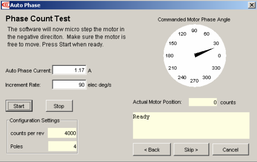
8 Click Start to begin the Phase Count Test. Observe status messages. See the prompt:
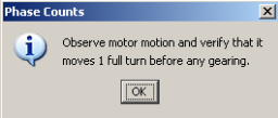
9 When you are ready to observe motion, click OK. See the prompt:
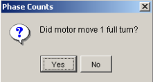
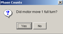
10 When you are ready to observe motion, click OK. See the prompt:
11 Click Next to open the Auto Phase Motor Phase Initialize screen:
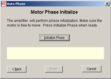
12 Click Initialize Phase to start phase initialization. If successful, this message appears: “Test Complete. Phasing has been initialized.”
13 Click Finish to close the screen and save values to flash memory.
14 After clicking Finish, the following message appears if changes were made:
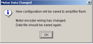
15 Click OK
10.2: Guidelines for Choosing Auto Phase Current and Increment Rate Values
Here are some considerations in choosing Auto Phase Current and Increment Rate values:
• If friction is high, then more current may be required to move the load.
• High static friction may require more current to overcome stiction.
• Transition from static friction to dynamic friction, and back, may produce jerky motion.
• A faster rate will operate in the dynamic friction range.
• A slower rate will operate in the static friction range.
• If the friction is low, as in the case of air bearings, low frequency oscillations may occur; thus, less current and slower rates may be required. If oscillations persist, then friction may need to be temporarily added.
10.3: Trouble Shoot the Auto Phase Process
1 Motor direction setup problems
If motor direction setup step failed:
Check Encoder or resolver power and signals.
Verify that the encoder is differential. (Contact factory if encoder is single-ended.)
Check shielding for proper grounding.
2 Motor wiring setup problems
If motor wiring setup step failed:
Verify that amplifier is disabled.
Check for mechanical jamming.
Check for smooth motion with no mechanical jerking.
Check for good connections to the motor power wires.
Disconnect motor power wires and measure for proper motor resistance.
3 Phase count test problems
If phase count test failed, verify that in the Motor/Feedback screen the following parameters have been set correctly:
Number of Poles for rotary motors. See Verify the motor’s pole count (p. 91).
Magnetic Pole Pair Length for linear motors
Encoder Lines or Fundamental Lines for rotary encoders.
Encoder Resolution for linear encoders.
4 Halls wiring setup problems
If Halls wiring setup step failed:
Check Halls power and signals.
Check for smooth motion with no mechanical jerking.
Check shielding for proper grounding.
If the auto phase procedure fails despite these corrective measures, see Phase Motor Manually.
10.4: Phase Motor Manually
The CME 2 Manual Phase tool lets the user phase a brushless motor, monitor signals, check configuration wiring, and control a microstepping current vector.
10.4.1: Manual Phase Example: Motor with Encoder
1 Make sure that no load is attached to the motor.
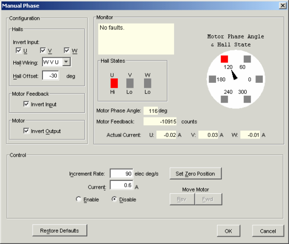
2 On the Main screen, choose ToolsManual Phase to open the window:
3  Verify the Current setting and then enable the amp by selecting Enable in the Control area of the Manual Phase window.
4  To control the current vector rotation, command the motor forward or reverse.
NOTE: Some motors have bearings stiction, so helping the motor with mechanical force is acceptable. Motors with no friction may need friction added to steady motion.
5 If the motor cannot keep up with the rate of vector rotation, then reduce the Increment Rate or increase the Current.
6 Verify that pressing forward button moves motor forward. If the motor moves in the wrong direction, toggle the Motor Invert Output setting
7 Verify actual position count agrees with direction of rotation: increasing counts in forward direction and decreasing counts in reverse direction. If it does not, toggle the Motor Feedback Invert Input box setting.
8 If the motor has no Halls, skip to Phase Initialization Steps for Motor without Halls.
9 Monitor the vector rotation through one electrical cycle for proper Hall transitions: Verify that the red indicator rotates in the same direction as the motor phase angle, and that the transition occurs when the needle is between indicators (±30 degrees, as shown below).
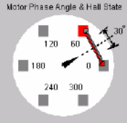
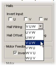
If the needle and Hall states do not track properly, use the Hall Wiring list box and/or Invert Input options (shown below) to swap the amplifier’s Hall wire configuration.
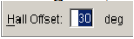
If the red indicator transition leads or lags behind the centered needle by more than 30 degrees, then try adjusting the Hall Offset in +/- 30 degree increments:
10 Phasing of a motor with encoder and Halls is complete. Click OK
Phase Initialization Steps for Motor without Halls
The Phase Initialization function is designed to phase a motor with no Halls.
Halls are strongly recommended for safe, redundant system.
Copley strongly recommends the use of Halls or a commutating encoder for commutation to provide a safe, redundant system. If the application requires otherwise, the customer accepts responsibility for verifying system performance and reliability.

Failure to heed these warnings can cause equipment damage, injury, or death.
The Phase Initialization function uses as little motion as possible (less than 1/3 of one electrical cycle) to determine phasing. Phase Initialization drives the motor in open loop current mode, using microstepping of a current vector.
1 This procedure is a continuation of Manual Phase Example: Motor with Encoder. Before proceeding, verify you have completed that procedure through Step 8.
2 Ensure that the motor is free to move (for instance, make sure the brake is OFF).
3 Ensure that no external force, such as gravity, will cause the motor to move. If it is not practical to eliminate such forces, it may be necessary to use the Forced Phase feature later in this procedure.
4  To phase a motor with an encoder and no Halls, click Initialize Phase. Observe the status messages under Monitor.
5 If the message “Phase Initialized” appears, the phasing of a motor with encoder and no Halls is complete. Click OK to close the Manual Phase window.
6. 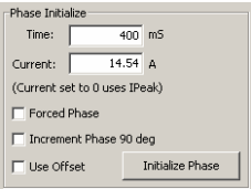
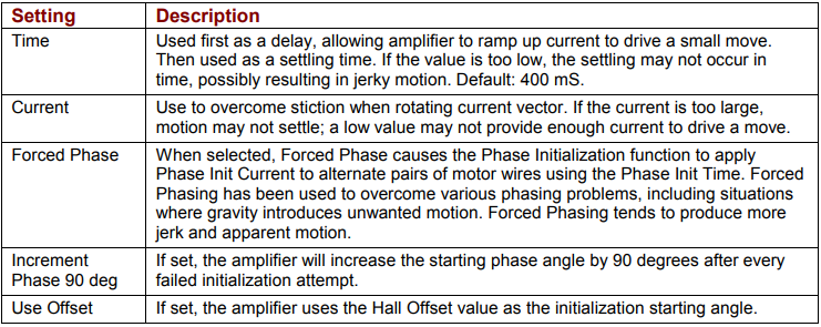
If the phasing function fails (for instance, message “Phase Initialized” is not displayed, or if a phasing fault is indicated) adjust the phase initialization settings described below and try Step 4 (Initialize Phase) again.
10.4.2: Manual Phase Example: Motor with Resolver
1 Make sure that no load is connected to the motor.
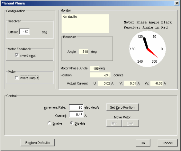
2 On the Main screen, choose ToolsManual Phase to open the window:
3
Verify the Current setting and then enable the amp by selecting Enable in the Control area of the Manual Phase window.
4 
To control the current vector rotation, command the motor forward or reverse.
NOTE: Some motors have bearings stiction, so helping the motor with mechanical force is acceptable. Motors with no friction may need friction added to steady motion.
5 If the motor cannot keep up with the rate of vector rotation, then reduce the Increment Rate or increase the Current.
6 Verify that pressing forward button moves motor forward. If it does not, toggle the Motor Invert Output box setting.
7 Verify actual position count agrees with direction of rotation: increasing counts in forward direction and decreasing counts in reverse direction. If it does not, toggle the Motor Feedback Invert Input box setting.
8 Adjust Resolver Offset configuration as required, testing Fwd and Rev, to produce alignment of Motor Phase Angle with Resolver Angle as shown here.
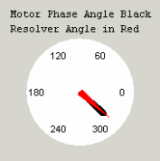
Note: Motor manufacturers typically align the resolver in 30 degree increments, typically by applying current through a pair of motor power wires.
10.5: Trouble Shoot Manual Phase w/ Encoder and Halls
To perform trapezoidal commutation after power-up or reset, the amplifier must receive good Hall signals. After the first Hall transition is detected, then sinusoidal commutation can be performed. In sinusoidal commutation, the amplifier uses the encoder for commutation while monitoring the Halls to verify proper phase. If the error between the encoder count and Hall transition is too large, then the Hall phase correction will not be performed and a phase fault will be triggered.
Test for phase fault problems in the order shown below.
1 Data accuracy test
Verify the motor’s pole count:
Apply a current vector at zero Increment Rate to lock motor in position.
Turn the motor shaft and count the number of distinct locking positions.
Calculate the number of poles: Poles = number of locking positions * 2
Verify the encoder line count OR a linear motor's magnetic pair length and the encoder resolution.
2 Encoder wiring test
If the Halls produce good trapezoidal commutation but a phase fault is persistent in sinusoidal commutation mode, the encoder is highly suspect. Try this:
Verify the differential encoder signals.
Verify proper twisted shielded cable with good grounding.
Disable the amplifier and move the motor manually to test for phase fault.
If phase fault only occurs under command of current, make sure the motor power cable is not bundled with the encoder cable
3 Hall signals test
If you suspect the Halls signals are faulty, try this:
Make sure Halls change states as the motor moves through one electrical cycle.
Some Hall signals are noisy and require filtering. Check with motor manufacturer.
Some Halls are not properly calibrated to the motor manufacturer’s specification.
4 Hall transition test
If you suspect that the location of the Hall transition is not within +/-30 degrees, try this:
Adjust Hall offset in smaller increments.
Verify Hall alignment.
Make sure motion is smooth.