14. CONTROL PANEL
Become familiar with the CME 2 Control Panel and its functions. Perform the steps outlined below to access the panel and its functions. Details follow in chapter.
1  Click to open the Control Panel:
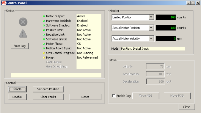
2 See this chapter for a Control Panel Overview and details on:
Status Indicators and Messages
Control Panel Monitor Channels
Control Functions
Jog Mode
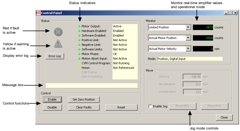
14.1: Control Panel Overview
Each of the Control Panel features labeled below is described in the following sections
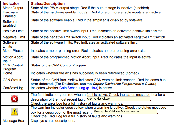
14.2: Status Indicators and Messages
The Status area includes status indicator lights (described below) and a message box. Any red lights indicate that motion will be inhibited.
14.3: Control Panel Monitor Channels
The Control Panel Monitor channels can display real-time values on up to three separate variables. The procedure follows.
Set up a monitor display channel
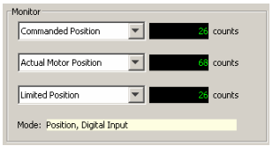
Click in the list box and select a variable from the list. Disabled disables the display. Other options represent the following amplifier values:
• Actual Current • Following Error • Passive Load Position
• Actual Motor Velocity • Commanded Current • Limited Position
• Actual Motor Position • Commanded Velocity • Analog Command
• Actual Load Velocity • Commanded Position • Bus Voltage
• Actual Load Position • Profile Velocity • Amplifier Temperature
• Velocity Error • Profile Acceleration • Motor Phase Angle
Mode: Displays the amplifier’s present operating mode. In camming it also
displays the active cam table number.
14.4: Control Functions
The Control area of the screen provides functions related to overall amplifier control. The screen options vary with model and configuration.
Use the Control Panel Control Functions
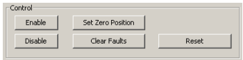
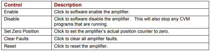
Control the operational state of the amplifier using the buttons as described below.
Risk of unexpected or uncontrolled motion.

Using the CME 2 Set Zero Position function while the amplifier is operating under external control could cause unexpected or uncontrolled motion.
Failure to heed this warning can cause equipment damage.
14.5: Jog Mode
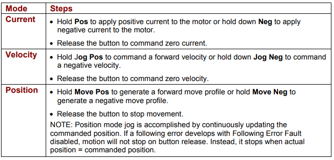
Jog mode provides a simple means for generating forward or reverse commands, as shown in the procedure below.
Run a move in jog mode
1 To put the amplifier in jog mode, set the Enable Jog option.
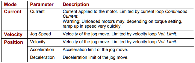
2 Set up a jog move by setting the following mode-specific parameters:
3 Command the move: