
15. SCOPE TOOL
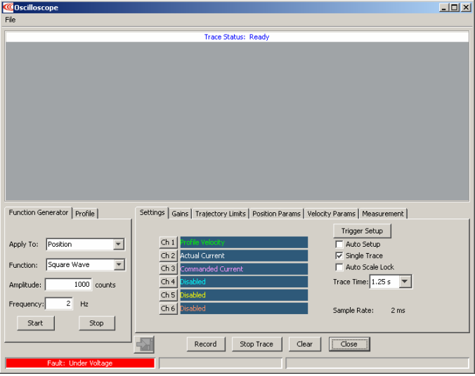
This chapter shows how to use the CME 2 Scope Tool to program and test motion sequences. Perform the steps outlined below to access the Scope Tool. Details follow in the chapter.
1  Click to open the Scope Tool:
2 See this chapter for a Scope Tool Overview and details on:
Function Generator and Profile Tabs
Trace Channel Variable Parameters
Trigger Setup
Trace Time, Sample Rate and Single Trace
Scope Display Parameters
Auto Setup
Measurement Tab
Control Loop Parameters
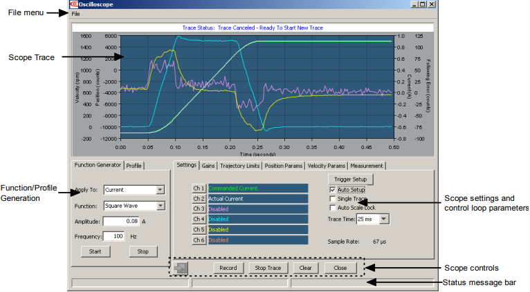
15.1: Scope Tool Overview
The Scope Tool can be used to tune the amplifier, monitor performance, and perform diagnostics. Function Generator and Profile Generator can drive the motor without external control. Auto Set Up feature sets typical initial values for scope parameters.
Run a move with the Function Generator or Profile Tool
1 Click on the Function Generator or Profile tab.
2 Adjust Function Generator or Profile settings, scope tool settings, gains, limits, and parameters (as described later in this chapter).
3 Click Start to begin move and trace. Click Stop to stop the move
Monitor externally controlled motion
1 As required, adjust scope tool settings.
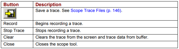
2 Click Record to begin trace.
3 Begin move with external controller. Click Stop Trace to stop the trace recording.
15.2: Function Generator and Profile Tabs
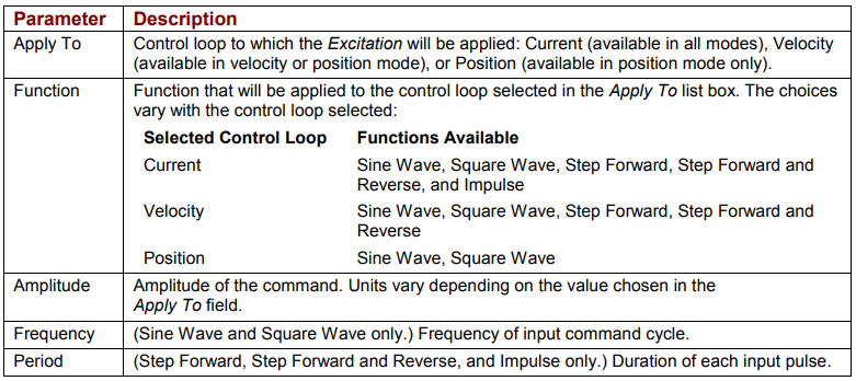
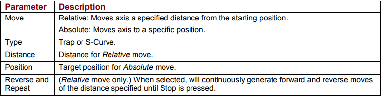
The Function and Profile generators can provide inputs to the different control loops for tuning and diagnostics purposes without using an external control source.
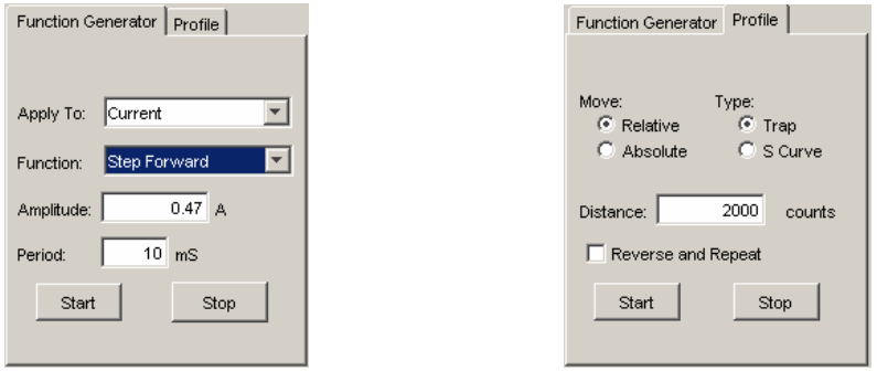
15.2.1: Function Generator Tab
15.2.2: Profile Tab
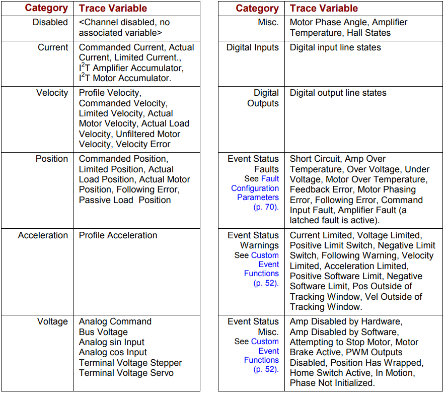
15.3: Trace Channel Variable Parameters
Choose a trace variable for display in a Scope channel
1  Click the channel button.
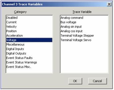
2 Choose a category and a trace variable.
3 Click OK.
15.4: Trigger Setup
Set up Scope trace trigger (manual setup)
1  Click Trigger Setup to open the screen:
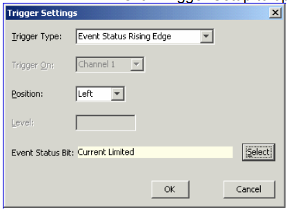
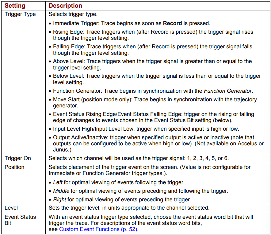
2 Choose from the settings described below:
15.5: Trace Time, Sample Rate and Single Trace
Trace Time sets the length of the recorded trace.
Sample Rate is the rate at which the signals are sampled. The rate depends on the trace time, the number of channels selected, and which variables are being traced.
Single Trace puts the scope in a single trace mode of operation. In this mode, the trigger is not re-armed after a trace until the user presses the Record button. Single Trace is automatically set by the generators in certain cases.
15.6: Scope Display Parameters
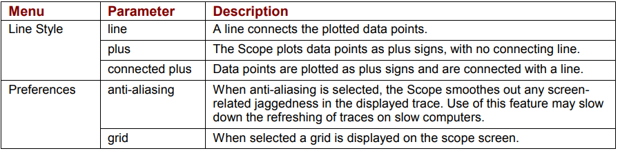
The user can set the line style and other scope screen preferences. Right-click on the scope screen to display the menus, as shown below.
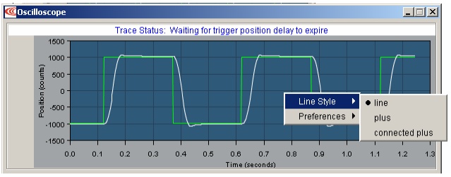
The Scope display parameters are described below
15.6.1: Auto Scale and Auto Scale Lock
The Scope automatically scales the display axes to optimally display all channels. With Auto Scale Lock selected, the y-axis locks its scale for all subsequent traces.
15.6.2: Zoom
Zoom in on a Trace Segment
1 Hold the left mouse button down while dragging a box around the area of interest
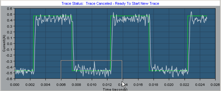
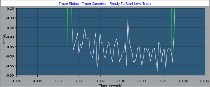
3 To restore the normal zoom level immediately, left-click anywhere on the trace. (Normal zoom level is also restored when the next trigger event occurs.)
15.7: Auto Setup
With Auto Set Up selected, if the function generator tab is active, CME 2 automatically sets the scope settings and the function generator's amplitude and frequency/period to best suit the function generator's Apply To and Excitation mode settings. If the Profile tab is active, CME 2 automatically sets the scope settings and sets a standard move into the profile generator. Changing any of the preset settings de-selects the Auto Set Up feature.
15.8: Measurement Tab
The Measurement tab allows you to measure and analyze data from up to three parameters during an interval defined by adjustable cursors. The Cursor Data area displays a parameter’s values at the left and right cursor locations, and the difference between the two values. The Analysis area displays the minimum, maximum, average, and root mean square of the parameters during the cursor period.
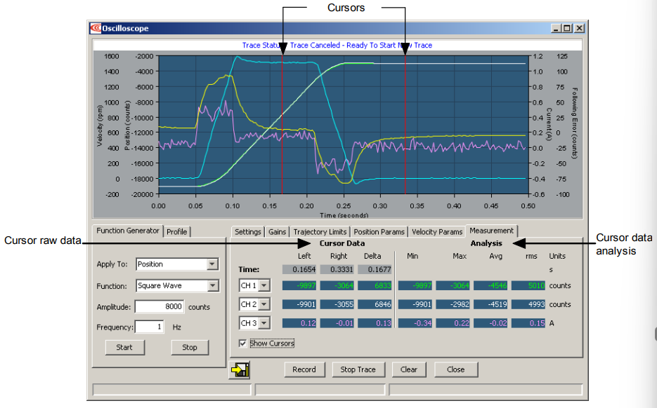
When Show Cursors is not set, the Cursor Data fields are inactive and the Analysis fields show calculations based on data from the entire trace cycle.
Basic Measurement Operations
1  To display cursors and activate the Cursor Data fields, set Show Cursors.
2 To move a cursor, click on the cursor and hold the left button while dragging the cursor to the desired location. Release the left button to place the cursor in the new location.
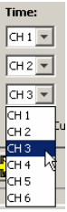
3 To select a parameter to measure and analyze within the cursors, choose a channel in one of the three channel lists on the Measurement tab:
15.9: Control Loop Parameters
The Scope tool provides convenient access to all of the control loop parameters that might be used in tuning and diagnosing an amplifier. The user can adjust these parameters and see the results immediately on the scope. Control loop parameters are accessed through a set of tabs, shown below.
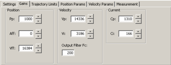
Note that the parameters represented on these tabs can also be accessed through the screens used to configure the control loops and the digital position input. Changing a value in the Scope tool automatically updates the value on the other screens where it appears, and vice versa.
Control loop parameter tab descriptions follow
15.9.1: Gains Tab
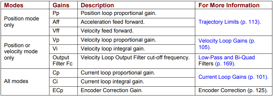
The Gains tab provides access to all of the gains appropriate to the operating mode, as described below.
15.9.2: Trajectory Limits Tab
In position mode, the Trajectory Limits tab can be used to set trajectory limits.
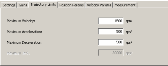
For more information on the velocity and acceleration limits, see Trajectory Limits. For more information on the Maximum Jerk setting, see Test S-Curve Profile
15.9.3: Position Loop Parameters
In position mode, the Position Params tab can be used to set position loop parameters
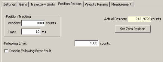
Set Zero Position sets the amplifier’s actual position count to zero. For more information on the other settings, see Position and Velocity Error Notes
15.9.4: Velocity Loop Parameters
In position and velocity modes, the Velocity Params tab can be used to set velocity loop parameters.
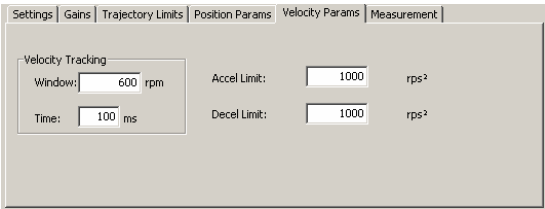
For information on the Velocity Tracking parameters, see Position and Velocity Error Notes. For information on the limits, see Velocity Loop Limits.
15.10: Scope Files
The Scope Tool allows you to save both scope settings and scope trace data. Saving the scope settings is useful for saving custom settings used for tests that are run frequently. Saving the trace data is useful for archiving the performance of a system so that it can be used as a reference at a later date for comparison.
15.10.1: Scope Settings Files
The Scope Tool FileSave Settings command allows you to save scope settings (settings on the Function Generator, Profile, and Settings tabs in a .sco file. The FileRestore Settings command restores them for quick setup.
Save scope settings:
1 On the Function Generator, Profile, and Settings tabs, choose the scope settings you wish to save.
2 Choose FileSave Settings.
3 When prompted, enter a File Name. If needed, navigate from the default ScopeData folder to another folder where you wish to store the file.
4 Click Save to save the .css file and close the screen.
Restore scope settings:
1 In the Scope Tool, choose FileRestore Settings.
2 If needed, navigate from the default ScopeData folder to the folder containing the .css file.
3 Highlight the filename and click Open
15.10.2: Scope Trace Files
The Scope Tool can save trace data in Copley Controls scope files (.sco files) that can be opened later with the CME 2 Trace Viewer. Simultaneously, a version of the same trace is stored in a comma-separated text file (.csv) and a tab delimited file (.txt), either of which can be opened with a spreadsheet application such as Microsoft Excel (or other programs) for mathematical analysis. The format of the .csv and the .txt file is the same:
Column 1: time
Column 2: Trace Channel 1
Column 3: Trace Channel 2 (if used)
Column n: Trace Channel n (if used)
NOTE: By default, scope files are saved in the ScopeData folder in the CME 2 installation folder. For instance, c:\Program Files\Copley Motion\CME 2\ScopeData. Use these procedures to save and view trace files:
Save trace data:
1 Generate the trace you wish to save.
2  In the Oscilloscope window, click the Save to Disk icon.
3 When prompted, enter a File Name. If needed, navigate from the default ScopeData folder to another folder where you wish to store the file.
4 Click Save to save the .sco, .txt, and .csv files in the same folder and close the screen.
View a trace file:
1 On the Main screen, choose ToolsView Scope Files to open the window.
2 Click Open File. When prompted, select the name of the file you wish to open. Then, click Open to display the file in the Trace Viewer window.
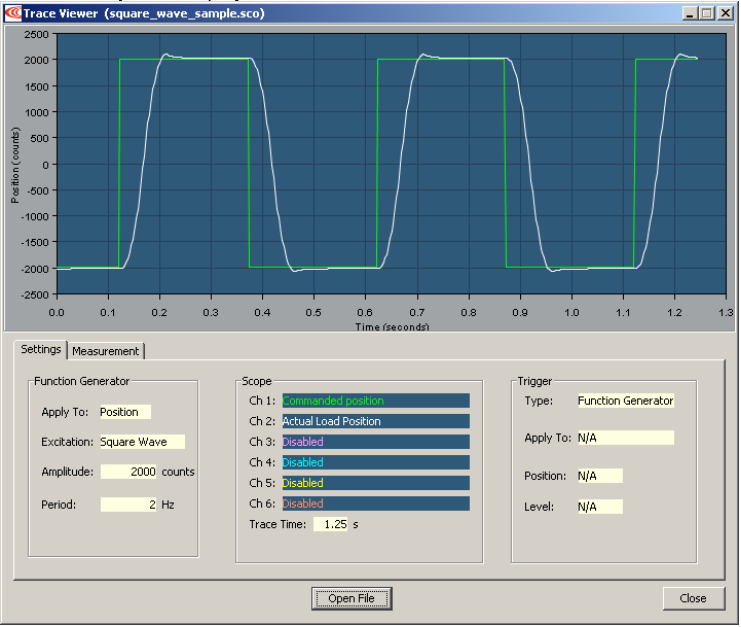
The Measurement tab allows you to measure and analyze data from up to three parameters during an interval defined by adjustable cursors. See Measurement Tab.