
2. INSTALLATION, STARTUP, AND INTERFACE TOUR
This chapter shows how to install, start, and set up communications for CME 2. Perform the steps outlined below. Details follow in the chapter.
1 Verify that the system on which you will install CME 2 meets the Host Computer Requirements
NOTE: Vista users see Special Notes for Vista Users
2 Install CME 2 Software
3 Start CME 2
4 Configure Serial Port Parameters (p. 14) or Configure CAN Network Parameters (To set up for DeviceNet control, see the Copley Controls Copley DeviceNet Programmer’s Guide.)
The chapter also includes CME 2 Interface Tour and describes how to Connect to an Amplifier in CME 2 (p. 17) and Rename an Amplifier
2.1: Install CME 2 Software
Optionally download software from the Web
1 Choose or create a folder where you will download the software installation file.
2 In an internet browser, navigate to: http://www.copleycontrols.com/Motion/Downloads/index.html
3 Under Software Releases, click on CME 2.
4 When prompted, save the CME2.zip file to the folder chosen or created in Step 1. The folder should now contain a file named CME2.zip.
5 Extract the contents of the zip file to the same location. The folder should now contain the files CME2.zip and Setup.exe.
6 If desired, delete CME2.zip to save disk space.
Install CME 2 Software
1 If installing from a CD, insert the CD (Copley Controls part number CME2). Normally, inserting the CD causes the installation script to launch, and a CME 2 Installation screen appears. If so, skip to Step 3.
2 If the software installation file is on a hard drive, navigate to the folder and then doubleclick on Setup.exe OR if you inserted the CD and the CME 2 Installation screen did not appear, navigate to the
root directory of the installation CD and then double-click on Setup.exe.
3 Respond to the prompts on the CME 2 Installation screens to complete the installation. We recommend accepting all default installation values.
NOTE: Vista users see Special Notes for Vista Users (p. 8).
2.2: Start CME 2 Software
1  Double-click the CME 2 shortcut icon on the Windows desktop to start CME 2.
2
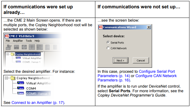
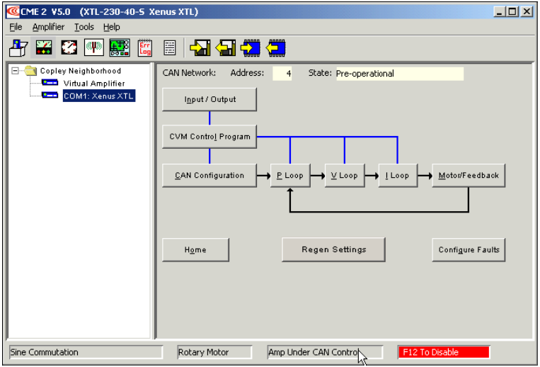
After an amplifier has been selected, the CME 2 Main Screen looks similar to this:
If the Basic Setup options have not been chosen, the Basic Setup screen opens.
2.3: Configure Serial Port Parameters
One or more serial ports on a PC can be used to connect amplifiers. Use the following instructions to add ports for amplifiers, to choose baud rates for those ports, and to remove ports for amplifiers.
Also use this procedure if the amplifier is to run under DeviceNet control. For more information, see the Copley Controls Copley DeviceNet Programmer’s Guide.
1.  Double-click the CME 2 shortcut icon on the Windows desktop to start CME 2.
If a serial or CAN port has not been selected, the Communications Wizard Select device screen appears.
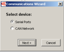
2 If the CME 2 Main screen appears instead of Select Device, choose ToolsCommunications Wizard.
3 Choose Serial Ports and click Next to open the Communications Wizard Select Ports/Serial Ports screen.
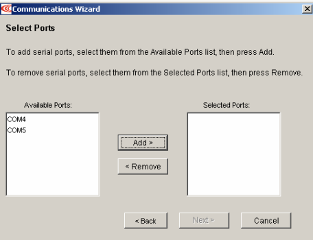
4 From the Available Ports list, choose the serial ports that will be used for amplifiers.
To allow an amplifier to connect through a port, select the port name and click Add.
To remove a port from Selected Ports, select the port name and click Remove.
...Configure Serial Port Parameters, continued:
5 Click Next to save the choices and open the Communications Wizard Configure Serial Ports screen.
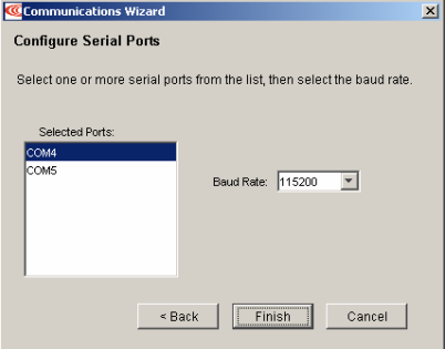
6. Configure the desired ports.
Highlight a port in the Selected Ports list.
Choose a Baud Rate for that port.
Repeat for each selected port.
7. Click Finish to save the choices.
2.4: Configure CAN Network Parameters
A CAN port can be used to connect the host PC to one or more amplifiers. Use the following instructions to configure CAN network settings.
1  Double-click the CME 2 shortcut icon on the Windows desktop to start CME 2.
If communications have not been set up, the Communications Wizard Select device screen appears.
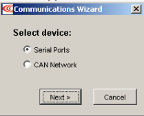
2 If the CME 2 Main screen appears choose ToolsCommunications Wizard.
3 Choose CAN Network
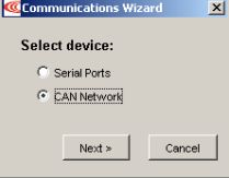
4 Click Next to open the Communications Wizard Configure CAN Network screen.
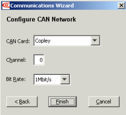
5 Choose the appropriate CAN Card, Channel, and Bit Rate, and click Finish.
NOTES:
1) The CAN Card list shows the manufacturer names of all supported CAN cards that have been connected to the PC and for which drivers have been installed.
2) All amplifiers must be set to the same bit rate (default is 1 Mbit/s).
2.5: Connect to an Amplifier in CME 2
Choose an amplifier by clicking on its name in the Copley Neighborhood. The neighborhood organizes amplifiers according to the connection method.
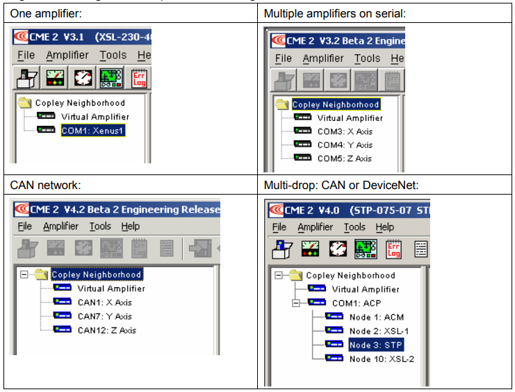
When there is only one amplifier available for connection, the software will connect automatically on startup.
2.6: Rename an Amplifier
Each amplifier represented in the Copley Neighborhood amplifier tree has a name. The default name for an amplifier is unnamed. Use this procedure to rename an amplifier.
1 Choose Main Menu AmplifierRename to open the Rename Amplifier screen.
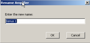
2 Enter the new name and click OK to close the screen.
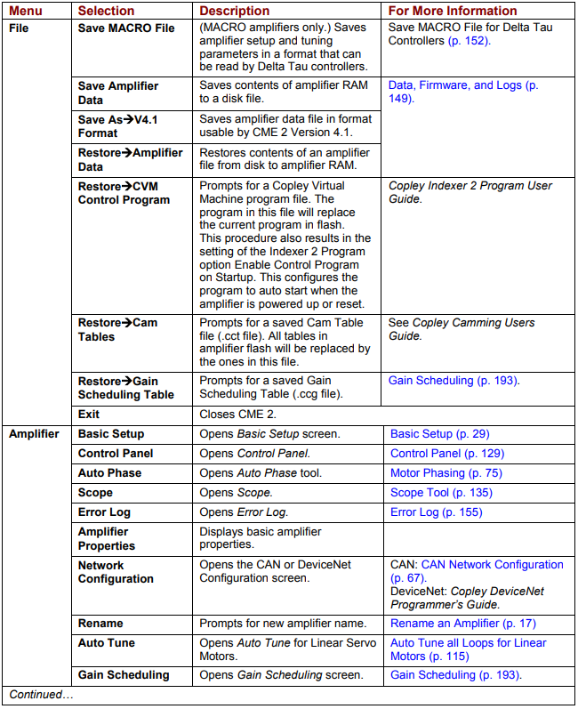
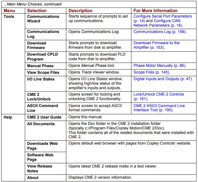
2.7: CME 2 Interface Tour
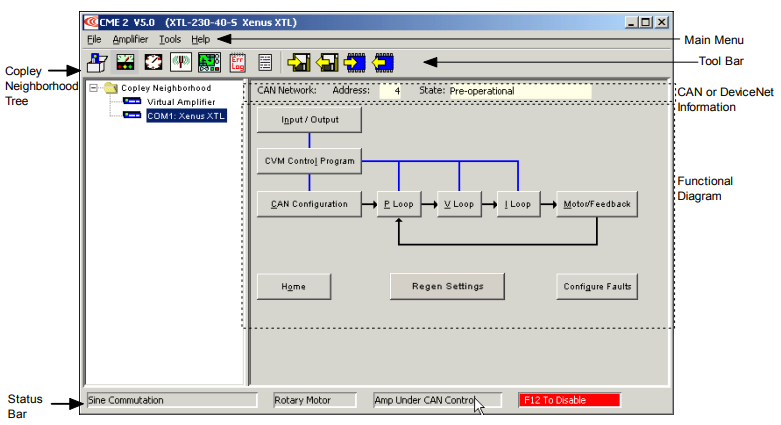
CME 2 features are called out in the diagram below. Screen details vary depending on amplifier model and mode selection. Details follow in the chapter.
2.7.1: Tool Bar Overview
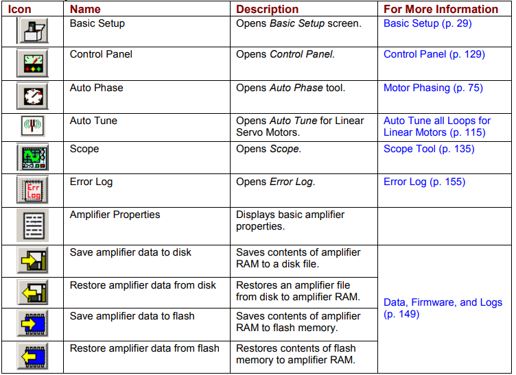
Click on any of the tools in the toolbar to access the tools described below
2.7.3: Functional Diagram
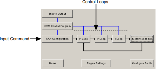
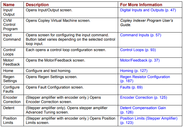
The functional diagram, shown below, provides button-click access to most of the screens used to configure an amplifier. It also indicates the flow of control from input, across all active control loops, to motor/feedback. Only those control loop buttons that are appropriate to the amplifier and operational mode appear on the diagram.
2.7.4: CAN or DeviceNet Information and Status Bar
CAN or DeviceNet Information
The Main screen displays the basic CAN or DeviceNet information. The example below shows CAN information:

The Address field shows the amplifier’s present CAN or DeviceNet address. For more information, see CAN Network Configuration (p. 67) or the Copley DeviceNet Programmer’s Guide. When the Position Loop Input is set to CAN, the State field shows the state of the amplifier’s CANopen state machine (for more information, see Copley Control’s CANopen Programmer’s Manual).
Status Bar
The status bar describes the present commutation mode, motor type, and amplifier control status as shown below. It also includes a reminder that pressing the F12 function key while CME 2 is running disables the amplifier.
