
5. MOTOR/FEEDBACK
This chapter describes motor, feedback, and brake parameters, and the Calculate function. Access these features as described below. Details follow in the chapter.
1  Click Motor/Feedback to open the Motor/Feedback screen.
2  Load Motor/Feedback/Brake Settings from a File
OR
2 Enter settings manually:
 Click the Motor tab to view or change Rotary Motor Setup Parameters or Linear Motor Setup Parameters
 Click the Feedback tab to view or change Feedback Parameters, Rotary or Feedback Parameters, Linear . Read the Feedback Notes for important related information.
 Click the Brake/Stop tab to view or change Brake/Stop Parameters. Read the Brake/Stop Notes for important related information.
 Use The Calculate Function to calculate initial gains and limits.
 On the Main screen, click Save to Flash to avoid losing the changes.
5.1: Motor/Feedback Screen Overview
A typical Motor/Feedback screen is shown below. Parameters vary with amplifier model.
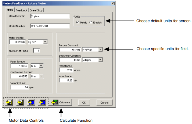
The Calculate function is described in The Calculate Function
Data on the Motor/Feedback screen can be saved to and restored from disk files using the controls described below.
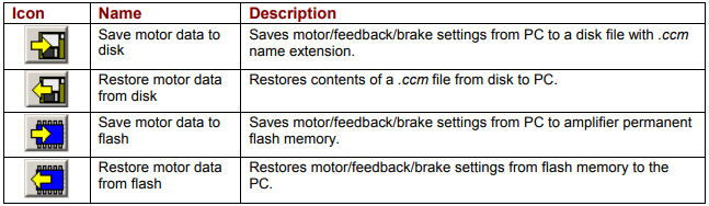
For more information see Data, Firmware, and Logs
5.2: Load Motor/Feedback/Brake Settings from a File
1 If needed, download the motor data file from the Copley Controls website: In an internet browser, navigate to http://www.copleycontrols.com/Motion/Downloads/motorData.html
Click on the appropriate motor name.
When prompted, save the file to the MotorData folder in the CME 2 installation folder.
(The default installation folder is C:\Program Files\Copley Motion\CME 2\MotorData.)
Extract the contents of the zip file to the same location.
The folder should now contain the new motor data file (with a .ccm filename extension).
If desired, delete the .zip file to save disk space.
2 Load the motor data into the amplifier:
 Click Motor/Feedback to open the Motor/Feedback screen.
On the Motor/Feedback screen, click Restore Motor Data from Disk. When prompted, navigate to the folder containing the file, then click on the file name, and then click Open.
 Calculate initial gains and limits with The Calculate Function
 On the Main screen, click Save to Flash to avoid losing the changes.
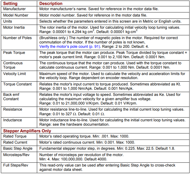
5.3: Rotary Motor Setup Parameters
View or change the settings described below. Options vary with amplifier model. Metric units are shown here.
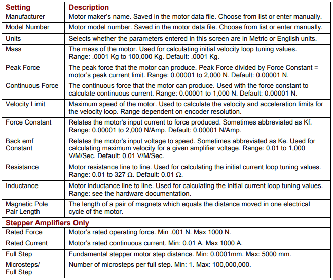
5.4: Linear Motor Setup Parameters
View or change the settings described below. Options vary with amplifier model. Metric units are shown here.
5.5: Feedback Parameters, Rotary
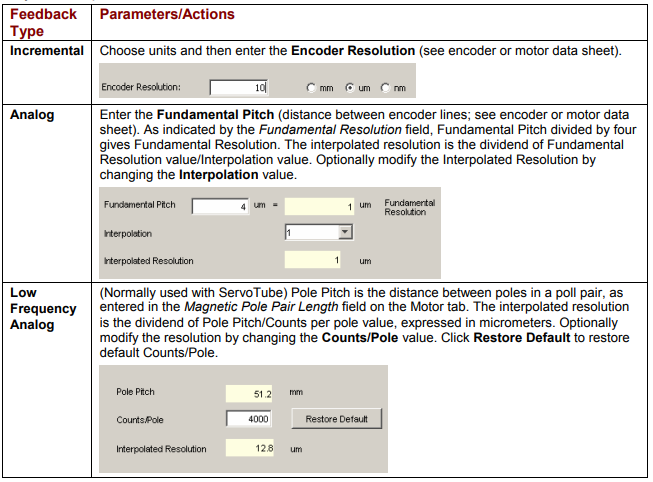
As appropriate for each encoder or resolver, enter the parameters described here. Options vary with amplifier model.
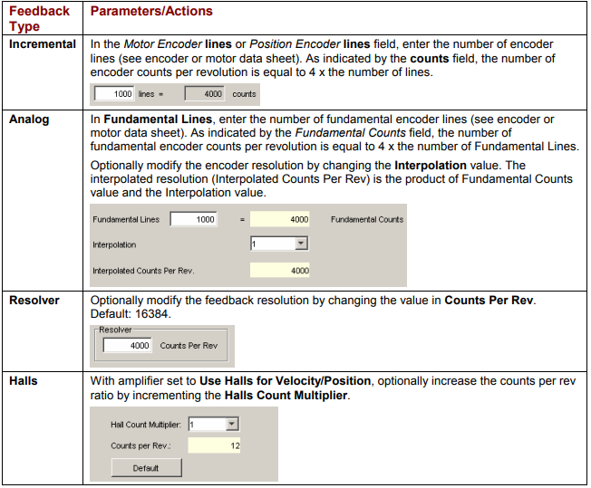
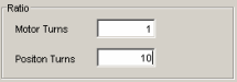
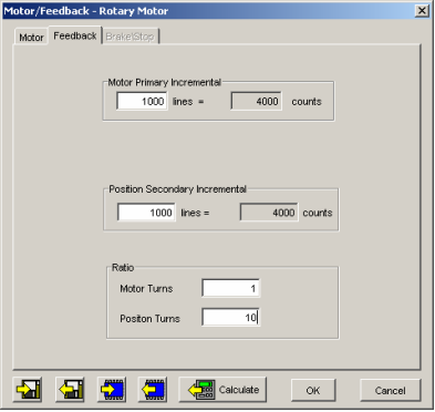
If two feedback devices are installed, verify that the values of Motor Turns to Position Turns correctly represent the ratio of motor encoder turns to position encoder turns. The details of the following screen may vary depending on the types of feedback devices present.
5.6: Feedback Parameters, Linear
As appropriate for each encoder installed, enter the parameters described below. Options vary with amplifier model
5.7: Feedback Notes
5.7.1: Encoder and Resolver Support
Some Copley Controls amplifiers are offered in multiple versions to support different types of encoder or resolver feedback. Some encoder versions support digital quadrature encoders, some support analog sin/cos encoders, and others support both. Encoder versions normally require Hall switches for the commutation of brushless motors. The resolver versions support standard, single speed, transmit-type resolvers.
5.7.2: Dual Feedback Amplifiers
Some Copley Controls amplifiers can receive position feedback from sensors on the motor, the load, or both, through the Primary Feedback channel, a Secondary Feedback channel (multi-mode port) or both. (Some amplifiers can also operate in certain modes without encoders or resolvers.)
When the amplifier is configured with a multi-mode port (see Feedback Options, p. 32) the multi-mode port can:
• Provide a buffered digital encoder output based on the digital encoder input.
• Provide an emulated digital encoder output based on the analog encoder or resolver input.
• Provide a second digital encoder input to be used in the dual encoder position mode. In this mode, an encoder attached to the load provides position loop feedback, and the motor encoder or resolver provides velocity loop feedback.
A dual-feedback setup is shown below. The amplifier receives feedback from an incremental motor encoder through the Primary feedback channel. Position (load) encoder feedback comes through the multi-mode port. The ratio of motor turns to position encoder turns is 1 to 10
5.8: Brake/Stop Parameters
Enter the following parameters as appropriate.

5.9: Brake/Stop Notes
Many control systems employ a brake to hold the axis when the amplifier is disabled. On brake-equipped systems, disabling the amplifier by a hardware or software command starts the following sequence of events.
• The motor begins to decelerate (at Abort Deceleration rate in position mode or Fast Stop Ramp rate in velocity mode). At the same time, the Brake/Stop Delay Time count begins. This allows the amplifier to slow the motor before applying the brake.
• When the motor slows to Brake/Stop Activation Velocity OR the Brake/Stop Delay Time expires, the brake output activates and PWM Delay Brake/Stop Response Time count begins.
• When response time has passed, the amplifier’s output stages are disabled. This delay ensures the brake has time to lock in before disabling the power section.
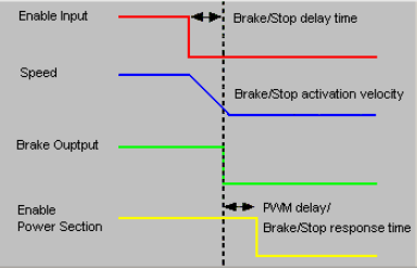
This sequence is not available in the current mode of operation. Instead, in current mode, the amplifier output turns off and the brake output activates immediately when the disable command is received.
5.10: The Calculate Function
The Calculate function uses programmed motor and encoder values to calculate initial gains and limits. These can be modified to fine-tune the amplifier. Follow the steps below:
1  Click Calculate to calculate and display the settings.
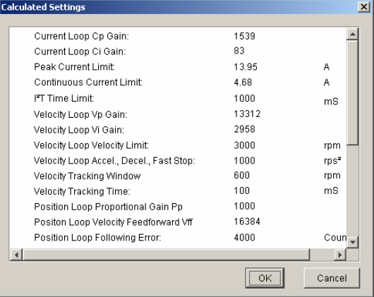
2 Verify the peak current limit, continuous current limit, and velocity loop velocity limit. If one or more of these values seems inappropriate, click Cancel and check: Peak Torque (or Force), Continuous Torque (or Force), Velocity Limit, and Torque (or Force) Constant. Correct them if needed. See Rotary Motor Setup Parameters or Linear Motor Setup Parameters.
If the Motor/Feedback values were correct but the peak current limit, continuous current limit, or velocity loop velocity limit values are not optimal for the application, change these limits during the tuning process.
3 Load the values into amplifier RAM by clicking OK.
NOTE: When loading motor data from a file, if the motor wiring configuration in the motor file does not match the configuration currently stored in the amplifier, CME prompts for verification on which configuration to use. Select the file configuration by clicking Yes. The configuration will be tested as part of Motor Phasing
4  On the Main screen, click Save to Flash to avoid losing the changes.