
6. DIGITAL INPUTS AND OUTPUTS
This chapter shows how to configure the amplifier’s digital inputs and outputs. Perform the steps outlined below. Details follow in the chapter.
1  Click Input/Output to open the Input/Output screen.
2 As needed, set Digital Inputs.
3 As needed, set Digital Outputs.
4 Click Close to close screen and save changes to amplifier RAM.
5  On the Main screen, click Save to Flash to avoid losing the changes.
6.1: Digital Inputs
6.1.1: Digital Inputs Screen Overview
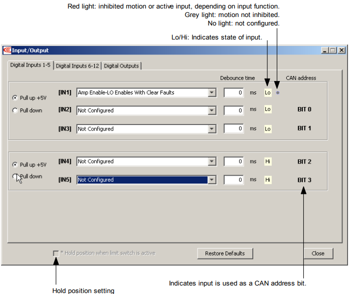
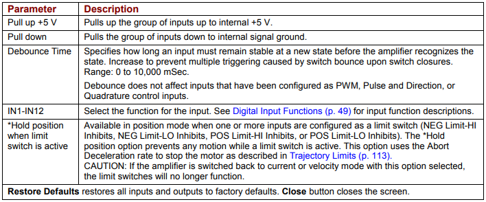
A typical Input/Output screen is shown below. (Features vary with amplifier model and configuration.)
6.1.2: Digital Input Functions
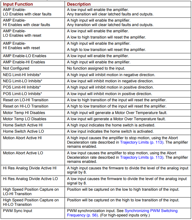
The programmable digital input functions are described below.
6.1.3: Standard Input Function Assignments
Enable Input: On most Copley Controls amplifiers, IN1 is dedicated to the enable function. Accelus uses IN2 for the enable function.
Other inputs can be programmed as additional enables. If there is more than one input programmed as an enable then all the inputs must be in the enabled state before the amplifier PWM output stage will be enabled.
Motor Over Temperature: On most Copley Controls panel amplifiers, IN5 is located on the motor feedback connector and is intended to be used for Motor Over Temperature.
Other: Other inputs may have predefined functions depending on mode of operation.
6.2: Digital Outputs
6.2.1: Screen Overview
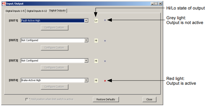
A typical Digital Outputs screen is shown below. Options vary with amplifier.

6.2.2: Standard Output Functions
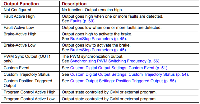
The standard output functions are described below. Custom output functions follow.
6.2.3: Custom Digital Output Settings: Custom Event
Any of the amplifier’s digital outputs can be programmed to respond to a combination of events including faults, warnings, and status indications. The output goes active when one or more of the selected events take place.
Configure a Custom Event output

1. Choose Custom Event for an output and then click Configure Custom to open the Event Configuration screen.
2 Select one or more Custom Event Functions Multiple functions are OR’ed together, so any event activates the output.
3 Choose Output Active High to have the output go high when active or Output Active Low to have the output go low when active.
4 To latch the output, set the Latch Output option.
The Clear button clears all check marks.
Latching an output does not eliminate the risk of unexpected motion with
non-latched faults.

Associating a fault with a latched, custom-configured output does not latch the fault itself. After the cause of a non-latched fault is corrected, the amplifier reenables without operator intervention. In this case, motion may re-start unexpectedly.
Failure to heed this warning can cause equipment damage, injury, or death.
5 Click OK to save changes to amplifier RAM and close the screen.
Custom Event Functions
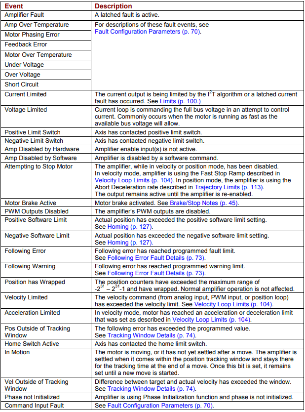
Select any combination of events to configure a custom event output:
Non-Latched vs. Latched Custom Event Digital Outputs
Like an amplifier fault, a custom-configured output can be non-latched or latched.
If a non-latched, custom-configured digital output goes active, it goes inactive as soon as the last of the selected events is cleared.
If a latched output goes active, it remains active until at least one of the following actions has been taken:
Power-cycle the amplifier
or Cycle (disable and then enable) an enable input that is configured as Enables with Clear Faults or Enables with Reset.
or  Access the CME 2 Control Panel and press Clear Faults or Reset.
Custom Event Output Fault Handling vs. Overall Fault Handling
A fault on an output programmed for Custom Event is separate from a fault on the amplifier. For instance, suppose:
• OUT3 has a Custom Event configuration. Only the Under Voltage fault condition is selected, and the output is latched.
• Under Voltage is not latched on the Configure Faults screen.
An under voltage condition occurs, and the amplifier goes into fault condition, output stages are disabled, and faults are reported. At the same time, OUT3 goes active.
The under voltage condition is corrected, and:
• The amplifier fault is cleared. Output stages are enabled.
• OUT3 remains active.
6.2.4: Custom Digital Output Settings: Custom Trajectory Status
Any of the amplifier’s digital outputs can be programmed to respond to a combination of amplifier trajectory status conditions. The output goes active when one or more of the conditions is met.
Configure a Custom Trajectory Status output
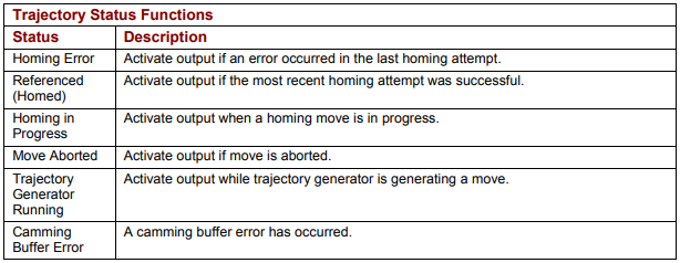
1  Choose Custom Trajectory Status for an output and then click Configure Custom to open the Trajectory Status Configuration screen.
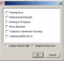
2 Select one or more trajectory status conditions described below. Multiple functions are OR’ed together, so any status match activates the output.
3 Choose Output Active High to have the output go high when active or Output Active Low to have the output go low when active.
4 Click OK to save changes to amplifier RAM and close the screen
6.2.5: Custom Output Settings: Position Triggered Output
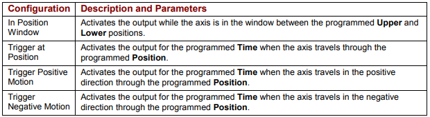
Any of the amplifier’s digital outputs can be programmed to respond in certain ways to the position of the controlled axis. The output goes active when the axis position meets the specified criteria.
Configure a Position Triggered output
1.  Choose Custom Position Triggered Output for an output and then click Configure Custom to open the In Position Configuration screen.
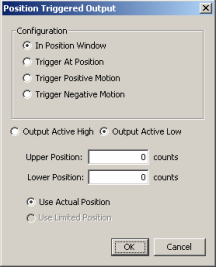
2 Select one of the configurations described below and enter appropriate values for the parameters.
3 Choose Output Active High to have the output go high when active or Output Active Low to have the output go low when active.
4 In stepper mode with no encoder, choose Use Limited Position. Otherwise choose Use Actual Position.
5 Click OK to save changes to amplifier RAM and close the Custom Output Configuration screen.
6.3: Synchronizing PWM Switching Frequency
In some situations, such as when sampling small analog signals, it is desirable to synchronize the PWM switching frequency among multiple amplifiers. In these cases, one amplifier serves as a master for one or more slave amplifiers. The PWM sync output of the master sends a signal that is received as a PWM sync input by each slave.