
7. COMMAND INPUTS
This chapter shows how to configure the amplifier’s command inputs. Perform the basic steps outlined below. Details follow in the chapter.
1  or
or  or
or  or
or  or
or  or
or  or
or 
Click to open the loop command input settings screen.
2 Change/verify command input parameters as described in the following sections:
Analog Command Settings
PWM Input Settings
Digital Position Input Settings or
CAN Network Configuration
Software Programmed Input Settings
Copley Camming User Guide
3 Click Close to close screen and save changes to amplifier RAM.
7.1: Analog Command Settings
View or change the settings described below.
7.1.1: Analog Command Notes
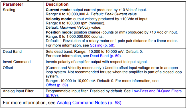
The amplifier can be driven by an analog voltage signal through the analog command input. The amplifier converts the signal to a current, velocity, or position command as appropriate for current, velocity, or position mode operation, respectively. The analog input signal is conditioned by the scaling, dead band, and offset settings.
Scaling
The magnitude of the command generated by an input signal is proportional to the input signal voltage. Scaling controls the input-to-command ratio, allowing the use of an optimal command range for any given input voltage signal range.
For example, in current mode, with default scaling, +10 Vdc of input generates a command equal to the amplifier’s peak current output; +5 Vdc equals half of that.
Scaling could also be useful if, for example, the signal source generates a signal range between 0 and +10 Vdc, but the command range only requires +7.5 Vdc of input. In this case, scaling allows the amplifier to equate +7.5 Vdc with the amplifier’s peak current (in current mode) or maximum velocity (in velocity mode), increasing the resolution of control.
Dead Band
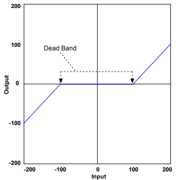
To protect against unintended response to low-level line noise or interference, the amplifier can be programmed with a “dead band” to condition the response to the input signal voltage. The amplifier treats anything within the dead band ranges as zero, and subtracts the dead band value from all other values. For instance, with a dead band of 100 mV, the amplifier ignores signals between –100 mV and +100 mV, and treats 101 mV as 1 mV, 200 mV as 100 mV, and so on.
Offset
To remove the effects of voltage offsets between the controller and the amplifier in open loop systems, CME 2 provides an Offset parameter and a Measure function. The Measure function takes 10 readings of the analog input voltage over a period of approximately 200 ms, averages the readings, and then displays the results. The Offset parameter allows the user to enter a corrective offset to be applied to the input voltage. The offset can also set up the amplifier for bi-directional operation from a uni-polar input voltage. An example of this would be a 0 to +10 Vdc velocity command that had to control 1000 rpm CCW to 1000 rpm CW. Scale would be set to 2000 rpm for a +10 Vdc input and Offset set to -5V. After this, a 0 Vdc input command would be interpreted as -5 Vdc, which would produce 1000 rpm CCW rotation. A +10 Vdc command would be interpreted as +5 Vdc and produce 1000 rpm CW rotation.
Monitoring the Analog Command Voltage
The analog input voltage can be monitored in the Control Panel and in the Scope Tool. The voltage displayed in both cases is after both offset and deadband have been applied.
Analog Command in Position Mode
The Analog Position command operates as a relative motion command. When the amplifier is enabled the voltage on the analog input is read. Then any change in the command voltage will move the axis a relative distance, equal to the change in voltage, from its position when enabled. To use the analog position command as an absolute position command, the amplifier should be homed every time it is enabled. The Homing sequence may be initiated by CAN, ASCII serial, DeviceNet, or CVM Indexer program commands.
7.2: PWM Input Settings
View or change the settings described below.
7.2.1: PWM Input Notes
Two Formats
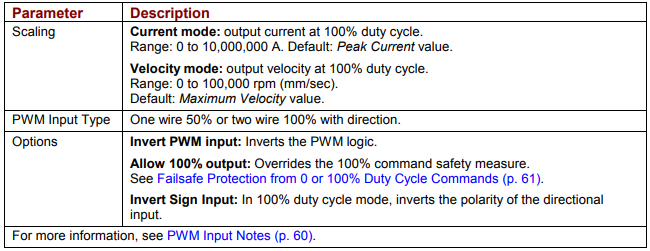
The amplifier can accept a pulse width modulated signal (PWM) signal to provide a current command in current mode and a velocity command in velocity mode. The PWM input can be programmed for two formats: 50% duty cycle (one-wire) and 100% duty cycle (two-wire).
50% Duty Cycle Format (One-Wire)
The input takes a PWM waveform of fixed frequency and variable duty cycle. As shown below, a 50% duty cycle produces zero output from the amplifier. Increasing the duty cycle toward 100% commands a positive output, and decreasing the duty cycle toward zero commands a negative output.
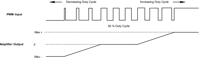
The command can be inverted so that increased duty cycle commands negative output and vice versa.
100% Duty Cycle Format (Two-Wire)
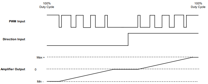
One input takes a PWM waveform of fixed frequency and variable duty cycle, and the other input takes a DC level that controls the polarity of the output. A 0% duty cycle creates a zero command, and a 100% duty cycle creates a maximum command level. The command can be inverted so that increasing the duty cycle decreases the output and vice versa.
Failsafe Protection from 0 or 100% Duty Cycle Commands
In both formats, the amplifier can be programmed to interpret 0 or 100% duty cycle as a zero command, providing a measure of safety in case of controller failure or cable break.
7.3: Digital Position Input Settings
View or change the settings described below.
7.3.1: Digital Position Input Notes
Three Formats
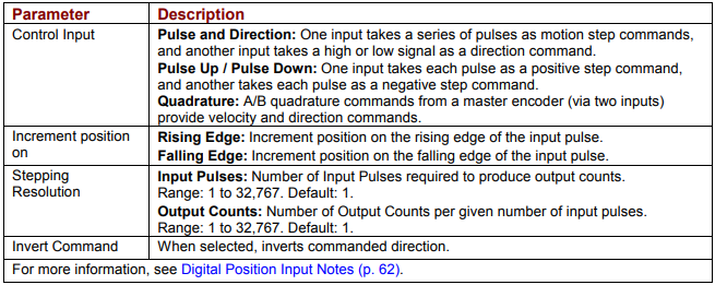
In position mode, the amplifier can accept position commands using one of these signal formats: pulse and direction, count up/count down, and quadrature. In all three formats, the amplifier can be configured to invert the command.
Pulse Smoothing
In digital position mode, the amplifier’s trajectory generator can be used to create trapezoidal profiles, with programmed acceleration, deceleration and velocity, from a simple pulse train or burst of pulses
To bypass the trajectory generator while in digital or analog position modes, set the maximum acceleration to zero. The only limits in effect will now be the velocity loop velocity limit and the current limits. (Note that leaving the maximum acceleration set to zero will prevent other position modes from operating correctly.)
Pulse and Direction Format
In pulse and direction format, one input takes a series of pulses as motion step commands, and another input takes a high or low signal as a direction command, as shown below.
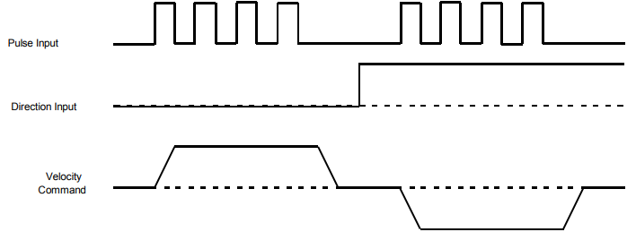
The amplifier can be set to increment position on the rising or falling edge of the signal. Stepping resolution can be programmed for electronic gearing.
Count Up/Count Down Format
In the count up/count down format, one input takes each pulse as a positive step command, and another takes each pulse as a negative step command, as shown below
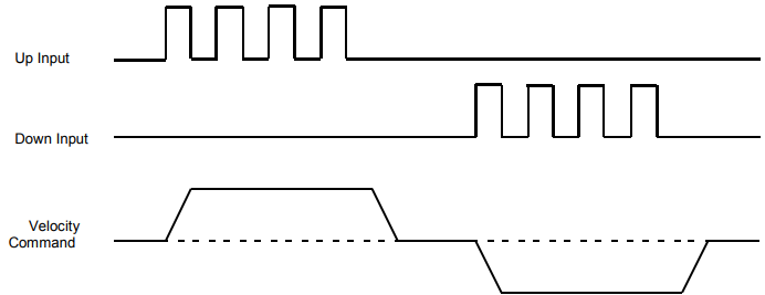
The amplifier can be set to increment position on the rising or falling edge of the signal. Stepping resolution can be programmed for electronic gearing.
Quadrature Format
In quadrature format, A/B quadrature commands from a master encoder provide velocity and direction commands, as shown below.
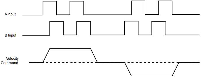
The ratio can be programmed for electronic gearing
7.4: Software Programmed Input Settings
These settings can be saved to flash to allow default conditions to be set and used when the amplifier is powered up or reset.
Potential for unexpected movement.
If Programmed Velocity or Programmed Current are set to values other than 0, the motor will move after power-up or reset if the amplifier is hardware enabled.
Failure to heed this warning can cause equipment damage, injury, or death.
7.4.1: Programmed Position
View or change the settings described below.

7.4.2: Programmed Velocity
View or change the setting described below.

7.4.3: Programmed Current
View or change the settings described below.
