
APPENDIX C: I2 T TIME LIMIT ALGORITHM
This chapter describes the algorithm used to implement the I2T limit.
C.1: I2 T Algorithm
C.1.1: I2 T Overview
The I2 T current limit algorithm continuously monitors the energy being delivered to the motor using the I2 T Accumulator Variable. The value stored in the I2 T Accumulator Variable is compared with the I2 T setpoint that is calculated from the user-entered Peak Current Limit, I2 T Time Limit, and Continuous Current Limit. Whenever the energy delivered to the motor exceeds the I2 T setpoint, the algorithm protects the motor by limiting the output current or generates a fault.
C.1.2: I2 T Formulas and Algorithm Operation
Calculating the I2 T Setpoint Value
The I2 T setpoint value has units of Amperes2 -seconds (A2 S) and is calculated from programmed motor data. The setpoint is calculated from the Peak Current Limit, the I2 T Time Limit, and the Continuous Current Limit as follows:
I2 T setpoint = (Peak Current Limit2 – Continuous Current Limit2 ) * I 2 T Time Limit
I2 T Algorithm Operation
During amplifier operation, the I2 T algorithm periodically updates the I2 T Accumulator Variable at a rate related to the output current Sampling Frequency. The value of the I2 T Accumulator Variable is incrementally increased for output currents greater than the Continuous Current Limit and is incrementally decreased for output currents less than the Continuous Current Limit. The I2 T Accumulator Variable is not allowed to have a value less than zero and is initialized to zero upon reset or +24 Vdc logic supply power-cycle.
Accumulator Increment Formula
At each update, a new value for the I2 T Accumulator Variable is calculated as follows:
I2 T Accumulator Variable n+1 = I2 T Accumulator Variable n +(Actual Output Current n+1 2 – Continuous Current Limit2 ) * Update period
After each sample, the updated value of the I2 T Accumulator Variable is compared with the I2 T setpoint. If the I2 T Accumulator Variable value is greater than the I2 T Setpoint value, then the amplifier limits the output current to the Continuous Current Limit. When current limiting is active, the output current will be equal to the Continuous Current Limit if the commanded current is greater than the Continuous Current Limit. If instead the commanded current is less than or equal to the Continuous Current Limit, the output current will be equal to the commanded current.
C.1.3: I2 T Current Limit Algorithm – Application Example
I2 T Example: Parameters
Operation of the I2 T current limit algorithm is best understood through an example. For this example, a motor with the following characteristics is used:
• Peak Current Limit – 12 A
• I2 T Time Limit – 1 S
• Continuous Current Limit – 6 A
From this information, the I2 T setpoint is:
I2 T setpoint = (12 A2 –6 A2) * 1 S = 108 A2 S
See the example plot diagrams on the next page.
I2 T Example: Plot Diagrams
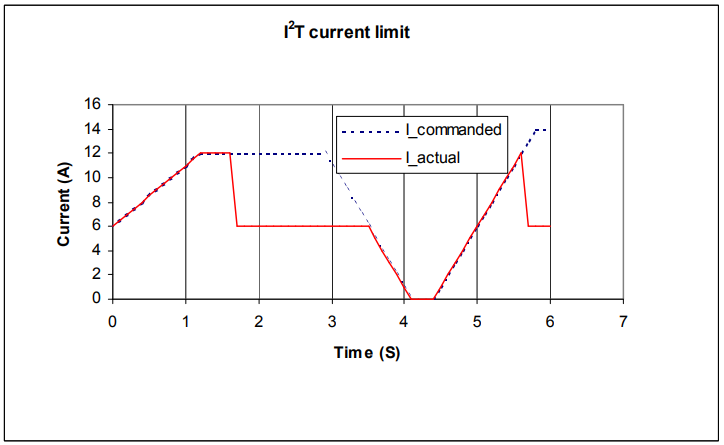
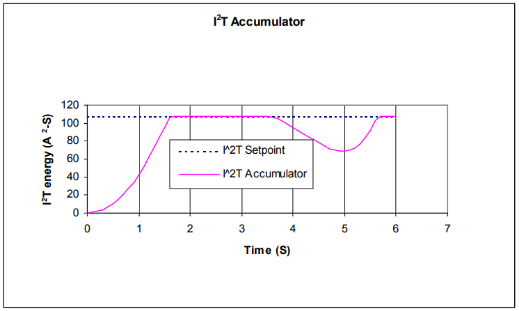
The plots that follow show the response of an amplifier (configured w/ I2 T setpoint = 108 A2 S) to a given current command. For this example, DC output currents are shown in order to simplify the waveforms. The algorithm essentially calculates the RMS value of the output current, and thus operates the same way regardless of the output current frequency and wave shape.
 A)
A)
 B)
B)
At time 0, plot diagram A shows that the actual output current follows the commanded current. Note that the current is higher than the continuous current limit setting of 6 A. Under this condition, the I2 T Accumulator Variable begins increasing from its initial value of zero. Initially, the output current linearly increases from 6 A up to 12 A over the course of 1.2 seconds. During this same period, the I2 T Accumulator Variable increases in a nonlinear fashion because of its dependence on the square of the current.
At about 1.6 seconds, the I2 T Accumulator Variable reaches a values equal to the I2 T setpoint. At this time, the amplifier limits the output current to the continuous current limit even though the commanded current remains at 12 A. The I2 T Accumulator Variable value remains constant during the next 2 seconds since the difference between the actual output current and the continuous current limit is zero. At approximately 3.5 seconds, the commanded current falls below the continuous current limit and once again the output current follows the commanded current. Because the actual current is less than the continuous current, the I2 T Accumulator Variable value begins to fall incrementally.
The I2 T Accumulator Variable value continues to fall until at approximately 5.0 seconds when the commanded current goes above the continuous current limit again. The actual output current follows the current command until the I2 T Accumulator Variable value reaches the I2 T setpoint and current limiting is invoked.
C.2: I2 T Scope Trace Variables
Two Scope Tool trace variables are available for monitoring whether the I2 T accumulator is accumulating or discharging. The I2 T Amplifier Accumulator variable evaluates the accumulator against the factory set current limits of the amplifier. The I2 T Motor Accumulator variable evaluates the accumulator against the userprogrammed current loop values. The value shown in the scope has been normalized so that 100% equals the I2 T setpoint.
When either trace variable line reaches 100%, current limiting will be invoked. For instructions on using these variables in the Scope Tool, see Trace Channel Variable Parameters