
3. PROGRAMMING
This chapter describes how to configure the Indexer 2 Program
3.1: Overview of Procedures
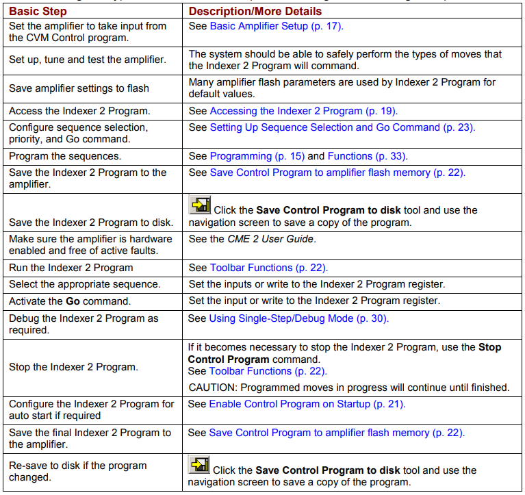
The following is a typical series of basic steps for creating and executing a sequence.
3.2: Basic Amplifier Setup
3.2.1: Typical Basic Amplifier Setup
In a typical Indexer 2 Program application, the amplifier is programmed to operate in position mode with a software programmed command source, as described below:
Access CME 2 by clicking on the desktop icon  or using the desktop Start menu command Copley MotionCME 2CME 2. When the F12 Disables Amplifier prompt appears, click OK. If necessary, select an amplifier in the Copley Neighborhood tree.
Click Basic Setup and then click Change Settings. Verify each set of Basic Setup options, using the Next button until you reach the Operating Mode options. Set Operating Mode to Position and set Position Loop Input to Software Programmed.
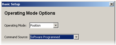
Click Next until the final Basic Setup screen (with the Finish button) opens.
Click Finish.
Verify that the amplifier has been configured, tuned and tested. See the CME 2 User Guide.
3.2.2: Using Indexer 2 with Other Modes and Command Sources
Indexer 2 Program setup controls are available in all operating mode/command source configurations. Likewise, Indexer 2 Program sequences can be launched in any operating mode/command source configuration.
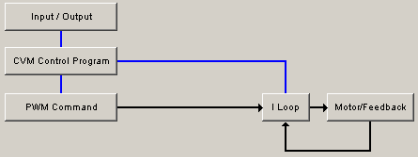
For instance, the amplifier can be configured to run in current mode using a PWM command source. In this case, the Indexer 2 Program controls are accessible through the CVM Control Program button on the CME 2 Main screen as shown below.
3.3: Accessing the Indexer 2 Program
On the CME 2 Main screen, click CVM Control Program to open the Copley Virtual Machine: Indexer 2 Program and I/O Line States screens.
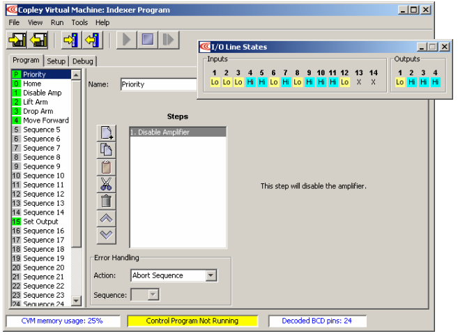
The Indexer 2 Program in the amplifier’s flash memory will be displayed. The numbers of sequences which have been programmed with steps will be displayed with a green background, as some of the sequences shown above. The I/O Line States screen shows real-time status of the amplifier’s digital inputs and outputs.
3.4: Indexer 2 Program Screen Overview
Major elements of the Indexer 2 Program screen are highlighted below.
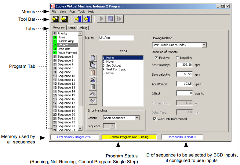
The Program tab is used to create and modify sequences.
See Creating and Modifying Sequences
and Adding Steps (Functions) to a Sequence
The Setup tab is used to set up sequence selection, Priority sequence, and Go command.
See Setting Up Sequence Selection and Go Command
The Debug tab is used to run the Indexer 2 Program in single-step/debug mode.
See Using Single-Step/Debug Mode
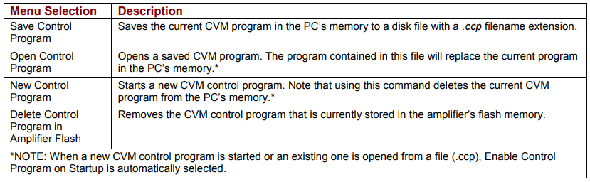

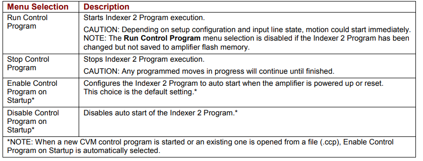

3.6: Toolbar Functions
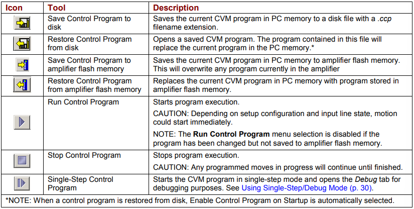
Near the top of the Indexer 2 Program screen is a set of tool buttons:

Click on the appropriate tool button to perform the functions described below:
3.7: Setting Up Sequence Selection and Go Command
Click Setup to access Sequence Selection, Go Command, and Priority Input Command controls.
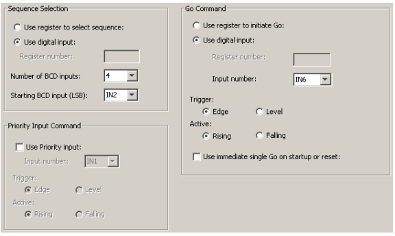
3.7.1: Sequence Selection
Use Register to Select Sequence
To configure register selection, click Use register to select sequence and then enter the Register number (range R0-R31) of the register which will contain the sequence number.
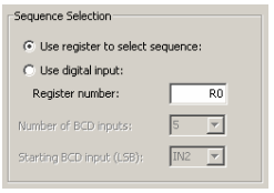
For information on writing the sequence number, see Use a Register to Select a Sequence.
Use Digital Input to Select Sequence
To configure Indexer 2 Program to use digital inputs for sequence selection, click Use digital input in the Sequence Selection box:
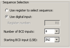
Select appropriate values for the following fields.

NOTE: The BCD inputs are only read when the Go command is received. The inputs can then be used for other purposes until the next Go command is expected. Exercise caution to avoid conflicting uses of an input.
3.7.2: Go Command
Choose one of the Go commands described below. Clicking Use immediate single Go on startup or reset triggers a Go command on start up or reset or when the Run button is pushed.
After that, the register or digital input Go commands function as programmed.
Use Register to Initiate Go
Click Use register to initiate go.
Enter the Register number (range R0-R31) of the Go command register. (If Use register to select sequence was also checked, the sequence selection register number will be changed to match Go command register number.)
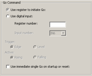
For information on setting the Go bit (Bit 15), see Use a Register to Initiate Go (p. 12).
Use Digital Input to Initiate Go
Click Use digital input.
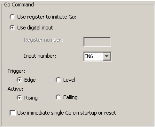
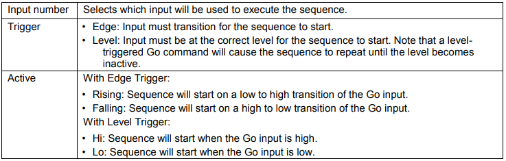
Select appropriate values for the following fields.
3.7.3: Priority Input Command
Click Use Priority input.
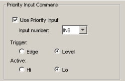
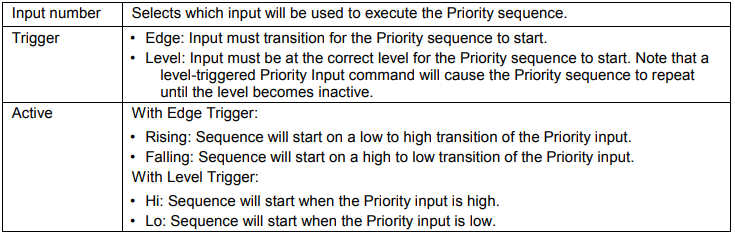
Select appropriate values for the following fields.
3.8: Creating and Modifying Sequences
The Program tab contains tools for creating sequences.
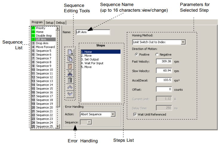
3.8.1: Tools and Controls
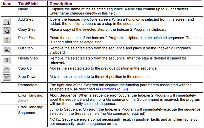
3.8.2: Sequence List
The sequence list has entries for the priority sequence and 32 sequences.
A green sequence number indicates that steps have been added to the sequence.
A grey sequence number indicates that no steps have been added to the sequence.
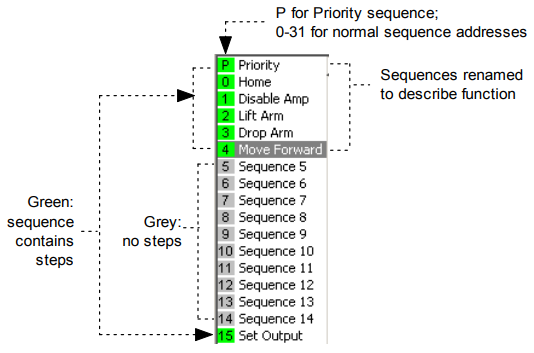
To change a sequence name, select the sequence and then enter the new name in the
Name field on the Program tab.
To program a sequence, select the sequence and proceed to
Adding Steps (Functions) to a Sequence
3.9: Adding Steps (Functions) to a Sequence
Select the sequence.
Click Add New Step  on the Program tab to open the Indexer Functions screen.
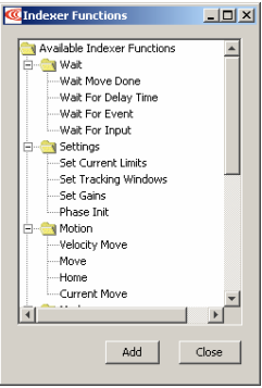
For function descriptions see Functions.
To add a function as a step at the end of the sequence, click the function name and then click Add.
To add a multiple functions, hold the Control key while clicking on the functions you wish to add, in the order in which you wish them to appear. Then click Add to add the steps to the sequence.
Program the functions as instructed in the function descriptions.
Click Close to close the screen.
See Overview of Procedures (p. 16) for a list of steps to perform to run the Indexer 2 Program.
3.10: Using Single-Step/Debug Mode
3.10.1: Overview
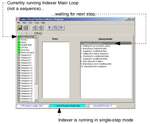
The Debug tab is used to display status information while the Indexer 2 Program is running in single-step/debug mode.
3.10.2: Entering Single-Step/Debug Mode
To single-step a sequence from the beginning:
1 Click Run Program  , then Stop Program
  and then Single Step Control Program
  .
.
OR
Click Save to Flash  and then Single Step Control Program
 .
.
The CVM program begins executing at the Indexer 2 Program Main loop level. The Debug Details frame contains the list of instructions associated with the current sequence step or Indexer 2 Main program state.
2 Click Single Step Control Program  as needed to proceed to the next step.
If the Indexer 2 Program is at a Wait step, the condition for the wait must be satisfied before the program will proceed.
To start single-stepping while an Indexer 2 Program is running:
1 Click Stop Program and then Single Step Control Program .
2 Click Single Step Control Program as needed to proceed to the next step.
If the program is at a Wait step, the condition for the wait must be satisfied before
the program will proceed.
In the example below, a Home step in Sequence 0 (named home) is ready to begin
with the next click of the Single Step Control Program button ( ).
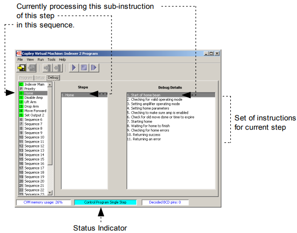
The set of instructions shown in Debug Details is an ordered list with conditional branches. For instance, if instruction 2, Checking for valid operating mode, determines that the current operating mode is valid for the move to be executed, then the program skips instruction 3, Setting amplifier operating mode and continues with instruction 4. Likewise, if step 8 finds move errors, then the program processes instruction 10, Returning an error, instead of 9, Returning success.
3.10.3: Exiting Single-Step/Debug Mode
Click Stop Control Program to exit single-step mode and stop the Indexer 2 Program.
Click Run Control Program to exit single-step mode and re-start the Indexer 2 Program.