
4. FUNCTIONS
This chapter describes the functions that can be used in an Indexer 2 Program sequence.
4.1: Using Registers to Pass Values to Functions
In many Indexer 2 Program function parameter fields, references to the program’s 32 registers can be used in place of hard-coded numbers. For instance, move parameters can be entered as numbers (at left, below) or as register references (at right, below).
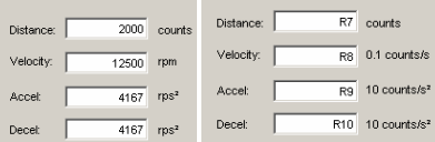
Note that in some cases, the units required for entry via the Indexer 2 Program screen are different from the units required by a register. Be sure to express all values in the units called for in the field label.
When the move is processed, the Indexer 2 Program performs the register value substitutions. Invalid data in a register will result in a sequence error.
To see the current register contents, use the ToolsView Register Values command.
4.2: Multi-Axis Amplifier Support
Some Copley Controls amplifier models can drive up to three separate axes, identified as Axis A, Axis B, and Axis C. On multi-axis amplifiers, the following Indexer 2 Program functions can be programmed per axis:
• Wait Move Done, Wait for Event, Wait for Position, Wait for Parameter.
• Set Current Limits, Set Tracking Windows, Set Gains.
• Velocity Move Position Mode, Move, Home.
• Disable Amplifier, Position Triggered Output, Get Set Parameter.
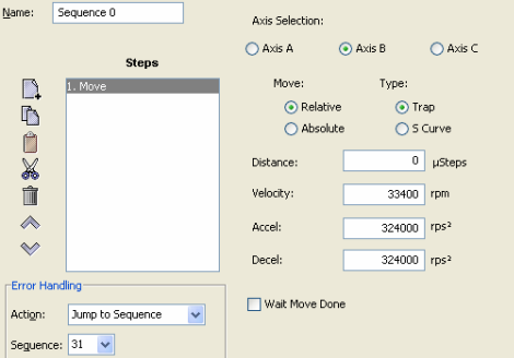
For instance, the Move function shown here is programmed for Axis B.
4.3: Wait Move Done
4.3.1: Wait Move Done Function Overview
Wait Move Done pauses execution of the sequence until the move in progress is completed.
4.3.2: Adding a Wait Move Done Step to a Sequence
Click Add New Step  on the Program tab to open Indexer Functions.
Click Wait: Wait Move Done to select the function. Click Add to add it to the sequence.
The Program tab displays the Wait Move Done parameters.
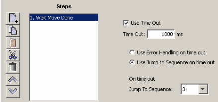
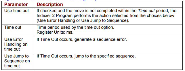
Choose appropriate values for the following parameters. Enter the Time out valuedirectly or enter the number (R0-R31) of an Indexer 2 Program register. See Using Registers to Pass Values to Functions
4.3.3: Wait Move Done Notes
Errors
A sequence error will occur if during the wait time:
The amplifier becomes hardware disabled.
The amplifier faults.
A software travel limit is reached or a hardware limit switch is activated.
A register used for a function parameter contains a value that is not valid for the parameter.
4.4: Wait for Delay Time
4.4.1: Wait for Delay Time Overview
Wait for Delay Time pauses execution of the sequence for the specified amount of time.
4.4.2: Adding a Wait for Delay Time Step to a Sequence
Click Add New Step  on the Program tab to open Indexer Functions.
Click Wait for Delay Time to select the function. Click Add to add it to the sequence. The Program tab displays the Wait for Delay Time parameters.
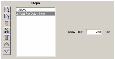
Enter the value directly or enter the number (R0-R31) of an Indexer 2 Program register. See Using Registers to Pass Values to Functions.

4.5: Wait for Event
4.5.1: Wait for Event Function Overview
Wait for Event pauses execution of the sequence until the specified event conditions are met.
4.5.2: Adding a Wait for Event Step to a Sequence
Click Add New Step  on the Program tab to open Indexer Functions.
Click Wait: Wait for Event to select the function. Click Add to add it to the sequence. The Program tab displays the Wait for Event parameters.
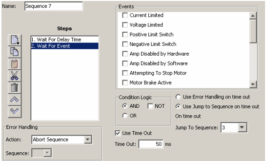
Select from the Events described on the next page. Set the condition logic and timeout controls described below as needed. Enter Time out time directly or enter the number (R0-R31) of an Indexer 2 Program register. See Using Registers to Pass Values to Functions.
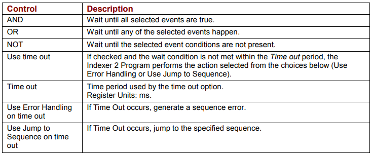
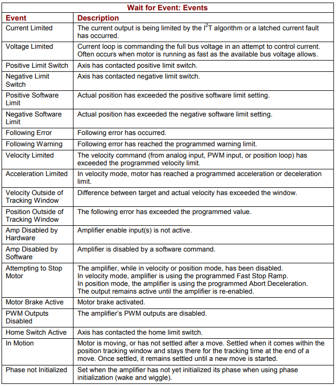
4.5.3: Wait for Event Function Notes
Errors
A sequence error will occur if this function is executed when a register used for a function parameter contains a value that is not valid for the parameter.
4.6: Wait for Input Mask
4.6.1: Wait for Input Mask Function Overview
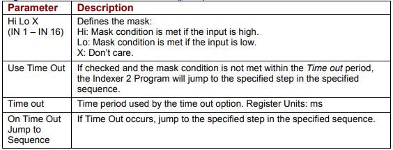
This function configures an Indexer 2 Program step to wait for the states of the amplifier’s digital inputs to match the specified mask before continuing to the next step.
4.6.2: Adding a Wait for Input Mask Step to a Sequence
Click Add New Step  on the Program tab to open Indexer Functions.
Click Wait: Wait for Input Mask to select the function. Click Add to add it to the sequence.
The Program tab displays the Wait for Input Mask parameters.
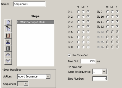
Choose appropriate values for the following parameters. Enter the Time out value directly or enter the number (R0-R31) of an Indexer 2 Program register. See Using Registers to Pass Values to Functions.
4.6.3: Wait for Input Mask Notes
Errors
A sequence error will occur if a register used for a function parameter contains a value that is not valid for the parameter.
4.7: Wait for Position
4.7.1: Wait for Position Overview
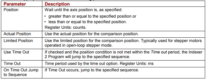
Wait for Position pauses execution of the sequence until the axis position meets the programmed criteria.
4.7.2: Adding a Wait for Position Step to a Sequence
Click Add New Step  on the Program tab to open Indexer Functions.
Click Wait: Wait for Position to select the function. Click Add to add it to the sequence.
The Program tab displays the Wait for Position parameters.
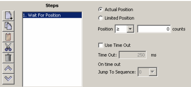
Choose appropriate values for the following parameters
4.8: Wait for Input
4.8.1: Wait for Input Overview
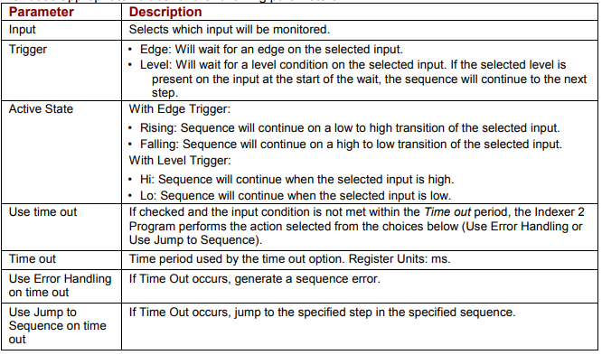
Wait for Input pauses execution of the sequence until the specified input condition is met.
4.8.2: Adding a Wait for Input Step to a Sequence
Click Add New Step  on the Program tab to open Indexer Functions.
Click Wait for Input to select the function. Click Add to add it to the sequence.
The Program tab displays the Wait for Input parameters.
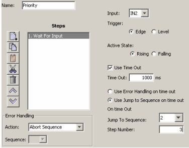
Choose appropriate values for the following parameters.
4.9: Wait for Parameter
4.9.1: Wait for Parameter Overview
Wait for Parameter pauses execution of the sequence until the specified condition is met.
4.9.2: Adding a Wait for Parameter Step to a Sequence
Click Add New Step  on the Program tab to open Indexer Functions.
Click Wait for Parameter to select the function. Click Add to add it to the sequence.
The Program tab displays the Wait for Parameter parameters.
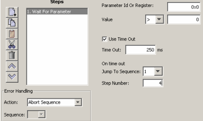
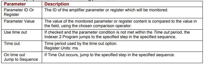
Choose appropriate values for the following parameters.
4.9.3: Wait for Parameter Function Notes
For a list of parameter IDs, see the Copley Parameter Dictionary. Use the ASCII ID value. Parameter IDs can be entered as decimal or hexadecimal numbers, using the 0x notation (for instance, 0x00c1). When the Indexer 2 Program reloads, all values will show in decimal form.
Due to the finite scan time of this function, the “equal to operator” should not be used with rapidly changing parameters such as actual velocity or actual current. Instead, chose “equal to or greater than” or “equal to or less than”.
Errors
A sequence error will occur if:
The specified parameter ID does not exist.
The specified parameter ID is for a flash only parameter.
The specified parameter returns more than two words.
4.10: Set Current Limits
4.10.1: Set Current Limits Function Overview
The Set Current Limits function changes the current limits.
4.10.2: Adding an Set Current Limits Step to a Sequence
Click Add New Step  on the Program tab to open Indexer Functions.
Click Settings:Set Current Limits to select the function. Click Add to add it to the sequence.
The Program tab displays the Set Current Limits parameters.
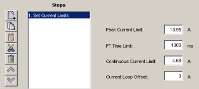
Choose appropriate values for the following parameters. Enter numeric values directly or enter the number (R0-R31) of an Indexer 2 Program register. See Using Registers to Pass Values to Functions
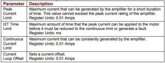
4.10.3: Set Current Limits Function Notes
Errors
A sequence error will occur if this function is executed when a register used for a function parameter contains a value that is not valid for the parameter.
4.11: Set Tracking Windows
4.11.1: Set Tracking Windows Function Overview
This function modifies the velocity and position tracking windows.
4.11.2: Adding a Set Tracking Windows Step to a Sequence
Click Add New Step  on the Program tab to open Indexer Functions.
Click Settings:Set Tracking Windows to select the function. Click Add to add it to the sequence.
The Program tab displays the Set Tracking Windows parameters.
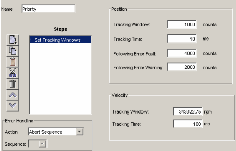
Choose appropriate values for the following parameters. Enter numeric values directly or enter the number (R0-R31) of an Indexer 2 Program register. See Using Registers to Pass Values to Functions
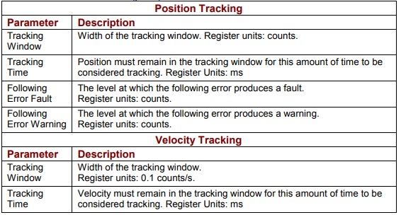
4.11.3: Set Tracking Windows Function Notes
Errors
A sequence error will occur if this function is executed when a register used for a function parameter contains a value that is not valid for the parameter.
4.12: Set Gains
4.12.1: Set Gains Function Overview
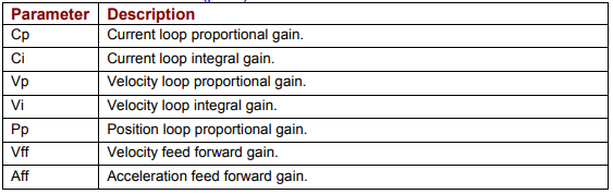
This function sets new gain values for the current, velocity and position loops during a sequence. This can be used, for instance, when the load on the axis has been changed. The new values will stay in effect for all sequences until changed again by another Set Gains function or by an amplifier reset.
4.12.2: Adding a Set Gains Step to a Sequence
Click Add New Step  on the Program tab to open the Indexer Functions screen.
Click Set Gains to select the function. Click Add to add it to the sequence.
The Program tab displays the Set Gains parameters.
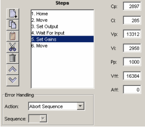
Choose appropriate values for the following parameters. Enter number values directly or enter the number (R0-R31) of an Indexer 2 Program register. See Using Registers to Pass Values to Functions
4.13: Velocity Move Position Mode
4.13.1: Velocity Move Position Mode Function Overview
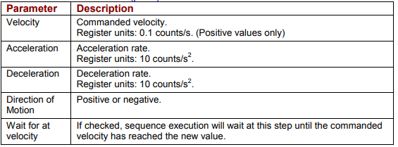
This function is used to change the operating mode of the amplifier to programmed position mode and configures a constant velocity trajectory.
4.13.2: Adding a Velocity Move Position Mode Step to a Sequence
Click Add New Step  on the Program tab to open Indexer Functions.
Click Motion:Velocity Move Position Mode to select the function. Click Add to add it to the sequence.
The Program tab displays the Velocity Move parameters.
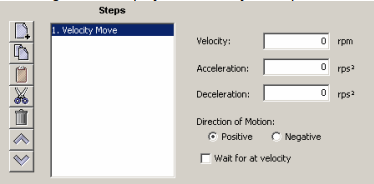
Choose appropriate values for the following parameters. Enter numeric values directly or enter the number (R0-R31) of an Indexer 2 Program register. See Using Registers to Pass Values to Function
4.13.3: Velocity Move Position Mode Notes
Errors
A sequence error will occur if this function is executed when:
The amplifier is hardware disabled.
The amplifier is faulted.
o Motor phasing is not initialized.
o A register used for a function parameter contains a value that is not valid for the parameter.
4.14: Move
4.14.1: Move Function Overview
The Move function executes a profile move using the specified parameters.
4.14.2: Adding a Move Step to a Sequence
Click Add New Step  to open the Indexer Functions screen.
Click Move to select the function. Click Add to add it to the sequence.
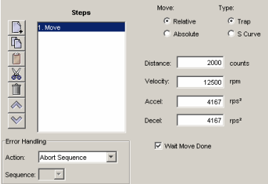
Choose appropriate values for the following parameters. Enter number values directly or enter the number (R0-R31) of an Indexer 2 Program register. See Using Registers to Pass Values to Functions
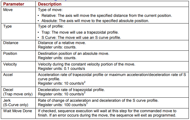
4.14.3: Move Function Notes
Wait Move Done
If Wait Move Done is not checked and a second move is commanded, the second move executes immediately with the following results:
If the second move is a relative, trapezoidal move, the axis moves the relative distance from where the axis was when the second move was executed.
If the second move is an absolute, trapezoidal move, the axis moves to the position specified by the second move.
If an S curve profile move is executed while another move is still in progress, an error occurs.
Errors
A sequence error will occur if:
The amplifier is hardware disabled when the Move begins, or becomes hardware disabled during the Move.
The amplifier has a fault when the move begins or a fault occurs during the move.
A software travel limit is reached or a hardware limit switch is activated during the move.
4.15: Home
4.15.1: Home Function Overview
The Home function executes a home command using the method and parameters specified.
4.15.2: Adding a Home Function Step to a Sequence
Click Add New Step  to open the Indexer Functions screen.
Click Home to select the function. Click Add to add it to the sequence.
The Program tab displays the Home function parameters.
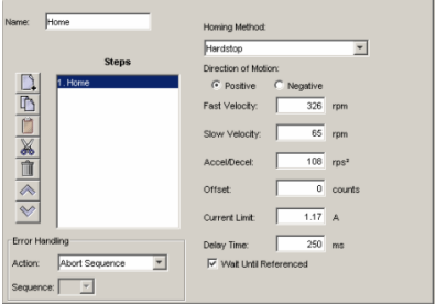
Choose appropriate values for the following parameters. Enter number values directly or enter the number (R0-R31) of an Indexer 2 Program register. See Using Registers to Pass Values to Functions
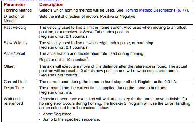
4.15.3: Home Function Notes
Do not execute a move function until the homing function is complete.
Errors
A sequence error will occur if:
The amplifier is, or becomes, hardware disable during the Homing function.
The amplifier has a fault at the beginning of the Home function or a fault occurs during the function.
Other sequence errors may occur that are specific to the homing method selected. See Homing Method Descriptions.
4.16: Current Move
4.16.1: Current Move Function Overview
This function is used to change the operating mode of the amplifier to programmed current mode and configure the mode.
4.16.2: Adding a Current Move Step to a Sequence
Click Add New Step  on the Program tab to open Indexer Functions.
Click Motion:Current Move to select the function. Click Add to add it to the sequence.
The Program tab displays the Current Move parameters.
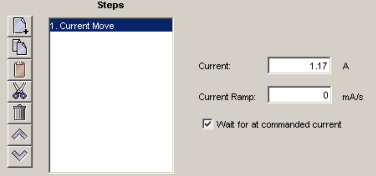
Choose appropriate values for the following parameters. Enter numeric values directly or enter the number (R0-R31) of an Indexer 2 Program register. See Using Registers to Pass Values to Functions
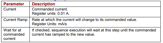
4.16.3: Current Move Notes
Errors
A sequence error will occur if this function is executed when:
The amplifier is hardware disabled.
The amplifier is faulted.
Motor phasing is not initialized.
A register used for a function parameter contains a value that is not valid for the parameter.
4.17: Velocity Move Velocity Mode
4.17.1: Velocity Move Velocity Mode Function Overview
This function is used to change the operating mode of the amplifier to programmed velocity mode and configures a constant velocity trajectory.
4.17.2: Adding a Velocity Move Velocity Mode Step to a Sequence
Click Add New Step  on the Program tab to open Indexer Functions.
Click Motion:Velocity Move Velocity Mode to select the function. Click Add to add it to the sequence.
The Program tab displays the Velocity Move parameters.
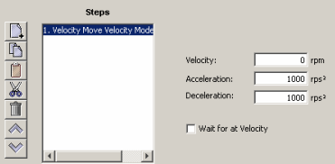
Choose appropriate values for the following parameters. Enter numeric values directly or enter the number (R0-R31) of an Indexer 2 Program register. See Using Registers to Pass Values to Functions
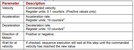
4.17.3: Velocity Move Velocity Mode Notes
Errors
A sequence error will occur if this function is executed when:
The amplifier is hardware disabled.
The amplifier is faulted.
Motor phasing is not initialized.
A register used for a function parameter contains a value that is not valid for the parameter.
4.18: Analog Velocity Mode
4.18.1: Analog Velocity Mode Function Overview
This function is used to change the operating mode of the amplifier to analog velocity mode and configure the mode.
4.18.2: Adding an Analog Velocity Mode Step to a Sequence
Click Add New Step  on the Program tab to open Indexer Functions.
Click Mode:Analog Velocity Mode to select the function. Click Add to add it to the sequence.
The Program tab displays the Analog Velocity Mode parameters.
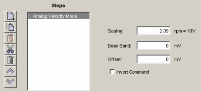
Choose appropriate values for the following parameters. Enter numeric values directly or enter the number (R0-R31) of an Indexer 2 Program register. See Using Registers to Pass Values to Functions
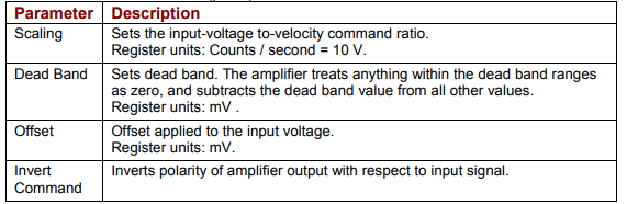
4.18.3: Analog Velocity Mode Notes
Errors
A sequence error will occur if this function is executed when:
The amplifier is hardware disabled.
The amplifier is faulted.
Motor phasing is not initialized.
A register used for a function parameter contains a value that is not valid for the parameter.
4.19: Analog Position Mode
4.19.1: Analog Position Mode Function Overview
This function is used to change the operating mode of the amplifier to Analog Position mode and configure the mode.
4.19.2: Adding an Analog Position Mode Step to a Sequence
Click Add New Step  on the Program tab to open Indexer Functions.
Click Mode: Analog Position Mode to select the function. Click Add to add it to the sequence.
The Program tab displays the Analog Position Mode parameters.
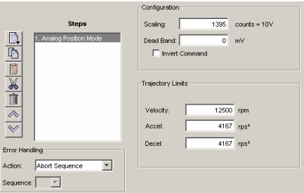
Choose appropriate values for the following parameters. Enter numeric values directly or enter the number (R0-R31) of an Indexer 2 Program register. See Using Registers to Pass Values to Functions
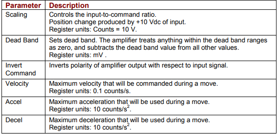
4.19.3: Analog Position Mode Notes
The analog position command operates as a relative motion command. When the amplifier is enabled the voltage on the analog input is read. Then, any change in the command voltage will move the axis a relative distance, proportional as programmed to the change in voltage, from its position when enabled.
To use the analog position command as an absolute position command, the amplifier should be homed every time it is enabled. A simple way to accomplish this is to program the priority sequence to use the same input as the enable input. The priority sequence would be programmed to home the axis. In this way, the axis will be automatically homed every time the amplifier is enabled.
Errors
A sequence error will occur if this function is executed when:
The amplifier is hardware disabled.
The amplifier is faulted.
Motor phasing is not initialized.
A register used for a function parameter contains a value that is not valid for the parameter.
4.20: Disable Amplifier
4.20.1: Disable Amplifier Function Overview
This function is used to software disable the amplifier.
4.20.2: Adding an Disable Amplifier Step to a Sequence
Click Add New Step  on the Program tab to open Indexer Functions.
Click Mode: Disable Amplifier to select the function. Click Add to add it to the sequence.
4.20.3: Disable Amplifier Notes
The amplifier will automatically re-enable with the execution of any function, such as Home or Move, which requires axis motion.
Errors
This function does not generate an error.
4.21: Camming Internal Master
4.21.1: Camming Internal Master Function Overview
This function is used to change the velocity of the Camming Internal Master.
4.21.2: Adding a Camming Internal Master Step to a Sequence
Click Add New Step  on the Program tab to open Indexer Functions.
Click Mode: Camming Internal Master to select the function. Click Add to add it to the sequence.
The Program tab displays the Camming Internal Master settings.
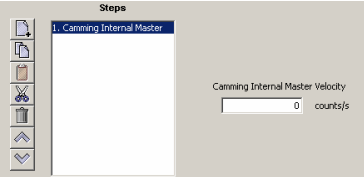
Choose appropriate values for the following parameter. Enter the velocity directly or
enter the number (R0-R31) of an Indexer 2 Program register. See Using Registers to
Pass Values to Functions

4.21.3: Camming Internal Master Function Notes
Errors
A sequence error will occur if this function is executed when a register used for a function parameter contains a value that is not valid for the parameter.
4.22: Camming
4.22.1: Camming Function Overview
This function is used to change the operating mode of the amplifier to Camming and to configure the Camming mode.
4.22.2: Adding a Camming Step to a Sequence
Click Add New Step  on the Program tab to open Indexer Functions.
Click Mode: Camming to select the function. Click Add to add it to the sequence.
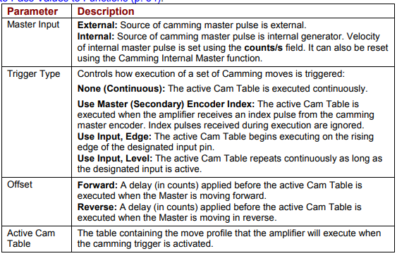
The Program tab displays the Camming mode settings.
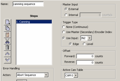
Choose appropriate values for the following parameters. Enter numeric values directly or enter the number (R0-R31) of an Indexer 2 Program register. See Using Registers to Pass Values to Functions
4.22.3: Camming Function Notes
The velocity of internal master pulse can be changed using the Camming Internal Master function.
The amplifier will stay in the camming mode of operation until another Indexer 2 Program function changes it or the amplifier is reset or power cycled.
Errors
A sequence error will occur if this function is executed when:
The amplifier is hardware disabled.
The amplifier is faulted.
Motor phasing is not initialized.
A register used for a function parameter contains a value that is not valid for the parameter.
4.23: Digital Position Mode
4.23.1: Digital Position Mode Function Overview
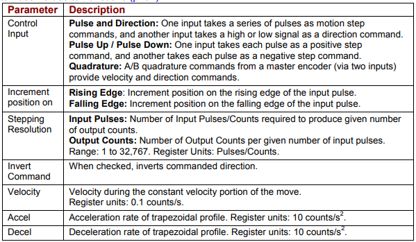
Change the operating mode of the amplifier to Digital Position mode and configure the mode.
4.23.2: Adding an Digital Position Mode Step to a Sequence
Click Add New Step  on the Program tab to open Indexer Functions.
Click Mode:Digital Position Mode to select the function. Click Add to add it to the sequence.
The Program tab displays the Digital Position Mode parameters.
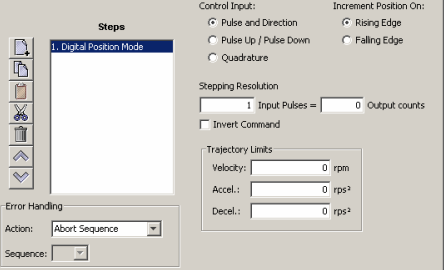
Choose appropriate values for the following parameters. Enter numeric values directly
or enter the number (R0-R31) of an Indexer 2 Program register. See Using Registers
to Pass Values to Functions
4.23.3: Digital Position Mode Notes
Errors
A sequence error will occur if this function is executed when:
The amplifier is hardware disabled.
The amplifier is faulted.
Motor phasing is not initialized.
A register used for a function parameter contains a value that is not valid for the parameter.
4.24: Velocity Loop Single Pole Output Filter
4.24.1: Velocity Loop Single Pole Output Filter Function Overview
This function modifies the Velocity Loop Output Filter.
4.24.2: Adding a Velocity Loop Single Pole Output Filter Step to a Sequence
Click Add New Step  on the Program tab to open Indexer Functions.
Click Filters:Velocity Loop Single Pole Output Filter to select the function. Click
Add to add it to the sequence.
The Program tab displays the Filter parameters.
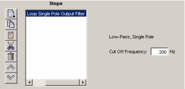
Enter a Cut Off Frequency value of between 1 and 1500.
4.24.3: Velocity Loop Single Pole Output Filter Notes
Errors
This function does not generate sequence errors.
4.25: Set Output
4.25.1: Set Output Overview
Set Output sets an output to the specified state.
NOTE: When this function is executed, it changes the configuration of the selected output to "Program Control, Active Low.” The “Program Control, Active Low” configuration will stay in effect until the amplifier is reset. Consider this effect when programming digital outputs.
4.25.2: Adding a Set Output Step to a Sequence
Click Add New Step  on the Program tab to open Indexer Functions.
Click Input/Output: Set Output to select the function. Click Add to add it to the sequence.
The Program tab displays the Set Output parameters.
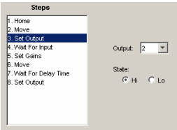
Choose appropriate values for the following parameters

4.26: Position Triggered Output
4.26.1: Position Triggered Output Function Overview
This function programs the amplifier to activate a digital output when the specified position criteria are met.
4.26.2: Adding a Position Triggered Output Step to a Sequence
Click Add New Step  on the Program tab to open Indexer Functions.
Click Input/Output: Position Triggered Output to select the function. Click Add to add it to the sequence.
The Program tab displays the Position Triggered Output settings.
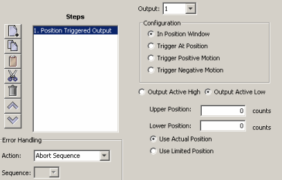
Choose appropriate values for the basic settings and configurations described below. Enter numeric values directly or enter the number (R0-R31) of an Indexer 2 Program register. See Using Registers to Pass Values to Functions
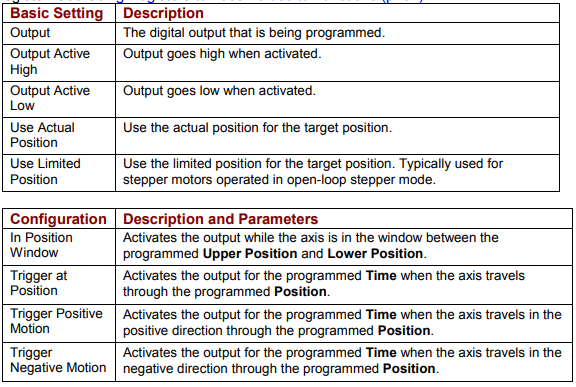
4.26.3: Position Triggered Output Notes
When this function is executed, it changes the configuration of the selected output to the chosen Position Triggered Output configuration. This configuration of the output will stay in effect until the amplifier is reset or the output configuration is changed by another function.
Errors
A sequence error will occur if this function is executed when a register used for a function parameter contains a value that is not valid for the parameter.
4.27: Math
4.27.1: Math Function Overview
This function is used to perform basic integer math and assign the result to an Indexer 2 Program register.
4.27.2: Adding a Math Step to a Sequence
Click Add New Step  on the Program tab to open Indexer Functions.
Click Tools: Math to select the function. Click Add to add it to the sequence.
The Program tab displays the Math settings.
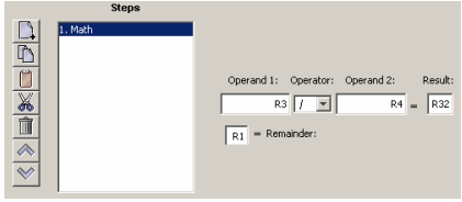
Choose appropriate values for the following parameters. Enter numeric values directly or enter the number (R0-R31) of an Indexer 2 Program register. See Using Registers to Pass Values to Functions
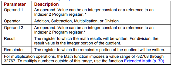
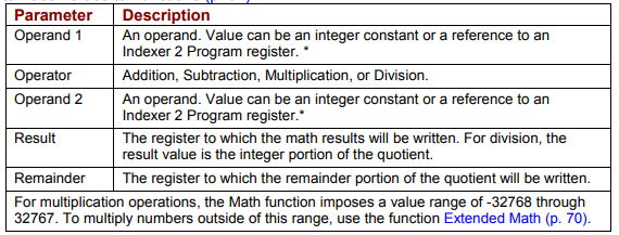
4.27.3: Math Function Notes
The Math function does not support carry on addition or borrow on subtraction. Thus, if a Math operation results in a number that exceeds the capacity of the register (between 231-1 and -231) the results will be incorrect (but no error will be generated).
Errors
A sequence error will occur if:
During multiplication, one of the operands is a register with a value less than -32768 or greater than 32767.
During division, Operand 2 is a register with a value equal to 0
4.28: If Register Set
4.28.1: If Register Set Function Overview
This function is used to conditionally assign a value to an Indexer 2 Program register.
4.28.2: Adding an If Register Set Step to a Sequence
Click Add New Step  on the Program tab to open Indexer Functions.
Click Tools: If Register Set to select the function. Click Add to add it to the sequence.
The Program tab displays the If Register Set settings.
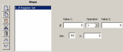
Choose appropriate values for the following parameters. Enter numeric values directly or enter the number (R0-R31) of an Indexer 2 Program register. See Using Registers to Pass Values to Functions
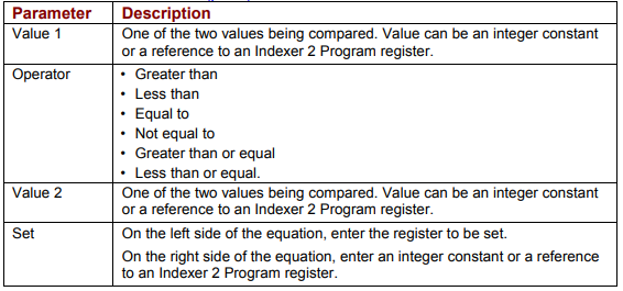
4.28.3: If Register Set Notes
When the Indexer 2 Program has been set up to use a register to select a sequence, the If Register Set function can determine which sequence will execute after the current sequence has finished.
Errors
This function does not generate an error.
4.29: Get Set Parameter
Get Set Parameter Function Overview
This function is used to get or set the value of one the amplifier’s internal parameters.
4.29.1: Adding a Get Set Parameter Step to a Sequence
Click Add New Step  on the Program tab to open Indexer Functions.
Click Tools: Get Set Parameter to select the function. Click Add to add it to the sequence.
The Program tab displays the Get Set Parameter settings.
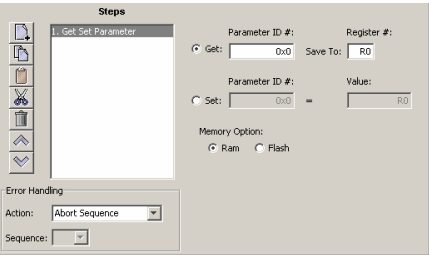
Choose appropriate values for the following settings. Enter numeric values directly or enter the number (R0-R31) of an Indexer 2 Program register. See Using Registers to Pass Values to Functions
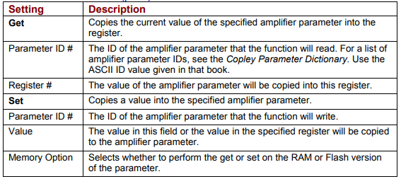
4.29.2: Get Set Parameter Notes
Parameter IDs can be entered as decimal or hexadecimal numbers. When entering hexadecimal numbers, use the 0x notation (for instance, 0x00c1). The Indexer 2 Program will convert and display all values in hexadecimal form.
Errors
A sequence error will occur if:
The specified parameter ID does not exist.
The specified parameter returns more than two words.
A set is attempted on a read only parameter.
A set is attempted and the value is illegal for the parameter being set.
4.30: Conditional Jump
4.30.1: Conditional Jump Overview
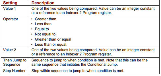
This function is used to conditionally jump to a specified step within a specified sequence. If the conditional statement is not true, the Indexer 2 Program continues to the next step in the original sequence.
4.30.2: Adding a Conditional Jump Step to a Sequence
Click Add New Step  on the Program tab to open Indexer Functions.
Click Tools: Conditional Jump to select the function. Click Add to add it to the sequence.
The Program tab displays the Conditional Jump settings.
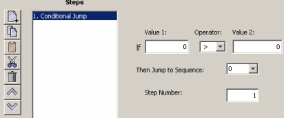
Choose appropriate values for the following parameters. Enter numeric values directly or enter the number (R0-R31) of an Indexer 2 Program register. See Using Registers to Pass Values to Functions
4.30.3: If Register Then Notes
If a jump is made to a sequence that has not been programmed or to a step in a sequence that does not exist, an error is not generated. Instead, the Indexer 2 Program will return to an idle state waiting for the next Go command.
Errors
This function does not generate sequence errors
4.31: Extended Math
4.31.1: Extended Math Function Overview
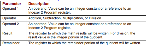
This function is used to perform basic integer math and assign the result to an Indexer 2 Program register. Extended Math is identical to Math (p. 66) except that Extended Math does not impose a size limit on multiplication operands.
4.31.2: Adding an Extended Math Step to a Sequence
Click Add New Step  on the Program tab to open Indexer Functions.
Click Tools: Extended Math to select the function. Click Add to add it to the sequence.
The Program tab displays the Extended Math settings.
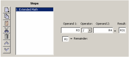
Choose appropriate values for the following parameters. Enter numeric values directly or enter the number (R0-R31) of an Indexer 2 Program register. See Using Registers to Pass Values to Function
4.31.3: Extended Math Function Notes
The Math function does not support carry on addition or borrow on subtraction. Thus, if a Math operation results in a number that exceeds the capacity of the register (between 231-1 and -231) the results will be incorrect (but no error will be generated).
Errors
A sequence error will occur if:
During division, Operand 2 is a register with a value equal to 0.
4.32: Logic
4.32.1: Logic Function Overview
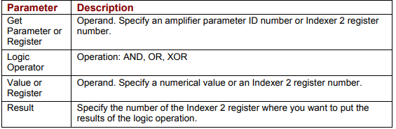
This function is used to perform logical operations on amplifier parameter values or Indexer 2 register values.
4.32.2: Adding a Logic Step to a Sequence
Click Add New Step  on the Program tab to open Indexer Functions.
Click Tools: Logic to select the function. Click Add to add it to the sequence.
The Program tab displays the Logic settings.
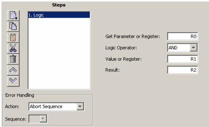
Choose appropriate values for the following parameters. Enter numeric values directly or enter the number (R0-R31) of an Indexer 2 Program register. See Using Registers to Pass Values to Funtions
4.32.3: Logic Function Notes
Parameter IDs can be entered as decimal or hexadecimal numbers. When entering hexadecimal numbers, use the 0x notation (for instance, 0x00c1). The Indexer 2 Program will convert and display all values in hexadecimal form.
Errors
A sequence error will occur if:
The specified parameter ID does not exist.
The specified parameter ID is for a flash only parameter.
The specified parameter returns more than two words.