
APPENDIX A: ASCII COMMANDS OVER SERIAL
The Indexer 2 Program provides 32 four-byte registers. They can be used to:
Select a sequence. See Use a Register to Select a Sequence.
Initiate a Go command. See Use a Register to Initiate Go.
Pass values to the Indexer 2 Program. See Using Registers to Pass Values to Functions.
This chapter describes how to set up connections for serial control and issue ASCII commands to access Indexer 2 Program registers
A.1: Connecting
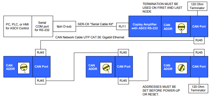
This section describes how to connect an amplifier for control via the RS-232 bus. The serially connected amplifier can also be used as a multi-drop gateway for access to other amplifiers linked in a series of CAN bus connections. Instructions for hooking up a single-axis connection and a multi-drop network appear below.
A.1.1: Single-Axis Connections
For RS-232 serial bus control of a single axis, set the CAN node address of that axis to zero (0). Note that if the CAN node address is switched to zero after power-up, the amplifier must be reset or power cycled to make the new address setting take effect.

A.1.2: Multi-Drop Network Connections
A serially connected amplifier can be used as a multi-drop gateway for access to other amplifiers linked in a series of CAN bus connections. Set the CAN node address of the serially connected amplifier (gateway) to zero (0). Assign each additional amplifier in the chain a unique CAN node address value between 1 and 127. For more information on CAN node address assignment, see the CAN Network Configuration chapter in the CME 2 User Guide. Use 120 Ohms termination on the first and last amplifier.
A.2: Communications Protocol
Use the following protocol for reading and writing Indexer 2 Program registers:
A.3: Reading and Writing Registers
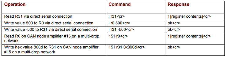
To read or write the Indexer 2 Program’s 32 registers with Copley ASCII commands, use the “i” (for Indexer) command with the “r” (for register) argument as shown here:
[optional node ID] i rn [optional write value] where:
[optional node ID] is the CAN node address of an amplifier in a multi-drop network. Range is 0-127. The node ID should be followed by a single space. If omitted, the serially connected amplifier is addressed by default.
i rn is the command code for accessing the Indexer 2 Program registers. Lowercase ASCII character i followed by a single space followed by r followed by a number n, where n is the number of the register to read or write. Range 0-31.
[optional write value] is the value to write to the register. A space is required between the register number and this value. If no value is entered, the command returns the value in the specified register. The value can be entered as a positive or negative integer or in hex format.
<cr> is a carriage return charter that ends the command line.
If a write command was accepted by the Indexer 2 Program, it returns an "ok" followed by a carriage return character. If a read command was accepted by the amplifier, it returns an "r " followed by the decimal equivalent of the registers value followed by a carriage return character. Examples:
If there was a problem with a command, the amplifier returns an "e" followed by an error code followed by a carriage return character. Error codes

Note that all register values are cleared when the Indexer 2 Program starts. For experimentation and simple setup and control, the CME 2 ToolsASCII Command Line tool can be used. In addition, a telnet device such as the standard Microsoft Windows HyperTerminal can be used to send commands in ASCII format. Use the protocol described in Communications Protocol