
5. MODBUS Electrical Interface
5.1. FnBus System
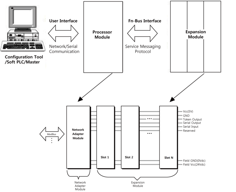
• Network Adapter Module
The Network Adapter Module forms the link between the field bus and the field devices with the Expansion Modules.
The connection to different field bus systems can be established by each of the corresponding Network Adapter Module, e.g. for SyncNet, PROFIBUS, CANopen, DeviceNet, Ethernet/IP, CC-Link, MODBUS/Serial, MODBUS/TCP etc.
• Expansion Module
The Expansion Modules are supported a variety of input and output field devices.
There are digital and analog input/output modules and special function modules.
• Two types of FnBus Message
- Service Messaging
- I/O Messaging
5.2. FnBus Pin Description
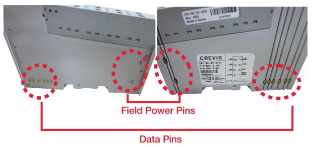
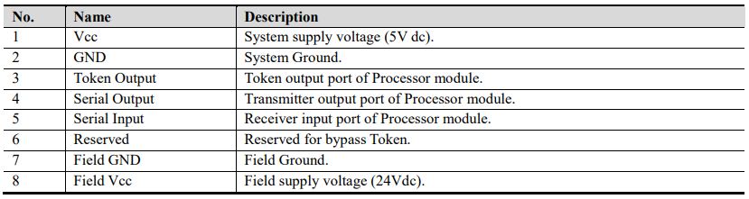
Communication between the NA series and the expansion module as well as system / field power supply of the bus modules is carried out via the internal bus. It is comprised of 6 data pin and 2 field power pin.

5.3. MODBUS Electrical Interface
5.3.1. Terminator Resistor
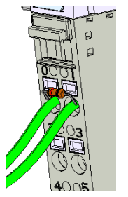
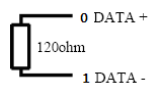
A reflection in a transmission line is the result of an impedance discontinuity that a traveling wave sees as it propagates down the line. To minimize the reflections from the end of the RS485-cable it is required to place a Line Termination near each of the 2 Ends of the Bus.
NA-9473 needs a termination resistor(120ohm) externally for more stable communication.
5.3.2. MODBUS DIP Switch Setup
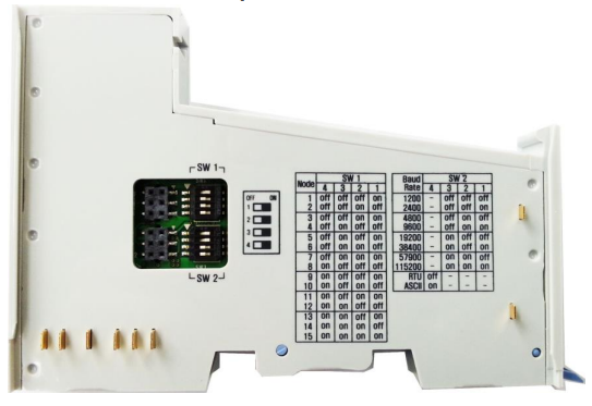
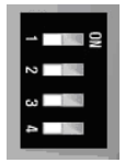
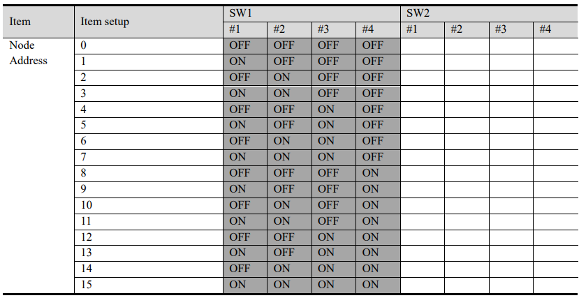
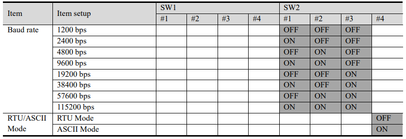
MODBUS Adapter interface configuration can be set by a DIP (4pole x 2) switch. This setup read once at power-up sequence, i.e. changes to DIP switch during operation does not affect MODBUS interface configuration.

5.3.3. I/O Process Image Map
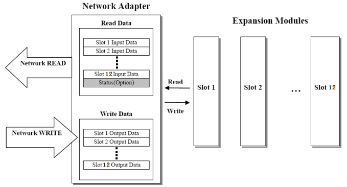
An expansion module may have 3 types of data as I/O data, configuration parameter and memory register. The data exchange between network adapter and expansion modules is done via an I/O process image data by FnBus protocol. The following figure shows the data flow of process image between network adapter and expansion modules.
5.3.4. MODBUS Interface Register / Bit Map
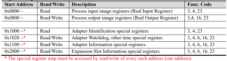
Register Map
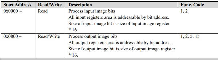
Bit Map
5.4. Example
5.4.1. Example of Input Process Image(Input Register) Map
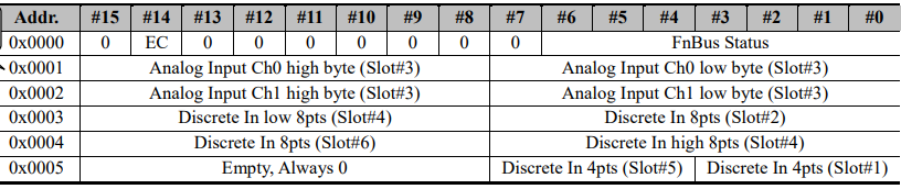
Input image data depends on slot position and expansion slot data type. Input process image data is only ordered by expansion slot position when input image mode is uncompressed (mode 0, 2). But, when input image mode is compressed (mode 1, 3), input process image data is ordered by expansion slot position and slot data type. Input process image mode can be set by special register 0x1114(4372). Refer to 6.3.3.
For example slot configuration
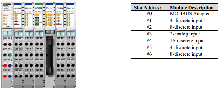
Input Process Image Mode#0 (Status(1word) + Uncompressed Input Processing Data)

FnBus Status :
0: Normal Operation 1: FnBus Standby
2: FnBus Communication Fault 3: Slot Configuration Failed
4: No Expansion Slot
EC (MODBUS Error Check) :
0: No Error CRC/LRC
1: Error CRC/LRC three times more sequentially since its last restart, clear counters operation, or power-up.
Input Process Image Mode#1 (Status(1word) + Compressed Input Processing Data)
Input Assembly Priority :
1) Analog Input Data (Word type)
2) 8 or 16 points Discrete Input Data (Byte type)
3) 4 points Input Data (Bit type)
4) 2 points Input Data (Bit type)
Input Process Image Mode#2 (Uncompressed Input Processing Data without Status), default input image

* FnBus uses the byte-oriented register mapping.
* Size of input image bit is size of input image register *16.
Input Assembly Priority :
1) Analog Input Data (Word type)
2) 8 or 16 points Discrete Input Data (Byte type)
3) 4 points Input Data (Bit type)
4) 2 points Input Data (Bit type)
5.4.2. Example of Output Process Image(Output Register) Map
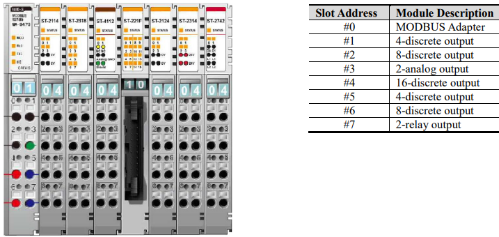
Output image data depends on slot position and expansion slot data type. Output process image data is only ordered by expansion slot position when output image mode is uncompressed (mode 0). But, when output image mode is compressed (mode 1), output process image data is ordered by expansion slot position and slot data type. Output process image mode can be set by special register 0x1115(4373). Refer to 6.3.3.
For example slot configuration
Output Process Image Mode#0 (Uncompressed Output Processing Data), default output image
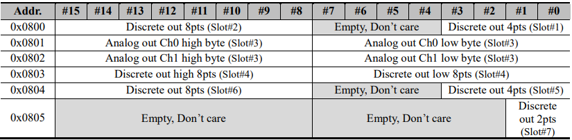
Output Process Image Mode#1 (Compressed Output Processing Data)
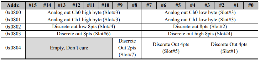
* FnBus uses the byte-oriented register mapping.
* Size of input image bit is size of input image register *16.
Output Assembly Priority :
1) Analog Output Data (Word type)
2) 8 or 16 points Discrete Output Data (Byte type)
3) 4 points Output Data (Bit type)
4) 2 points Output Data (Bit type)