6. MODBUS INTERFACE
6.1. MODBUS Transmission Mode
Two different serial transmission modes are defined: The RTU mode and the ASCII mode. It defines the bit contents of message fields transmitted serially on the line. It determines how information is packed into the message fields and decoded.
6.1.1. RTU Transmission Mode
When devices communicate on a MODBUS serial line using the RTU (Remote Terminal Unit) mode, each 8–bit byte in a message contains two 4–bit hexadecimal characters. The main advantage of this mode is that its greater character density allows better data throughput than ASCII mode for the same baud rate. Each message must be transmitted in a continuous stream of characters.

6.1.2. ASCII Transmission Mode
When devices are setup to communicate on a MODBUS serial line using ASCII (American Standard Code for Information Interchange) mode, each 8–bit byte in a message is sent as two ASCII characters. This mode is used when the physical communication link or the capabilities of the device does not allow the conformance with RTU mode requirement regarding timers management.

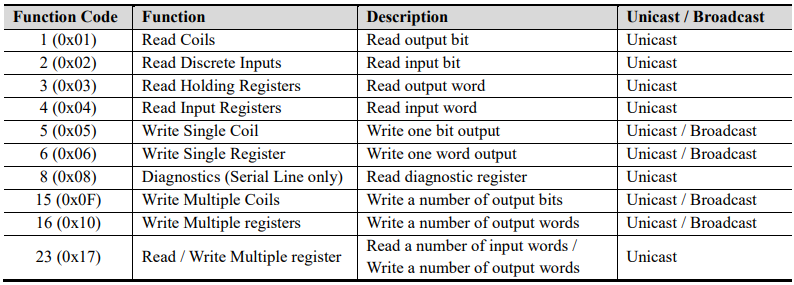
6.2. Supported MODBUS Function Codes
6.2.1. 1 (0x01) Read Coils
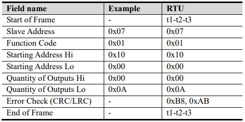
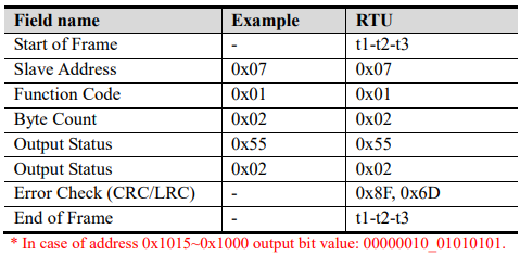
This function code is used to read from 1 to 2000 contiguous status of coils in a remote device. The Request PDU specifies the starting address, i.e. the address of the first coil specified, and the number of coils. In the PDU Coils are addressed starting at zero. Therefore coils numbered 1-16 are addressed as 0-15. The coils in the response message are packed as one coil per bit of the data field. Status is indicated as 1= ON and 0= OFF.
Request
Response
6.2.2. 2 (0x02) Read Discrete Inputs
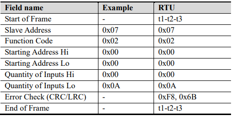
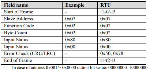
This function code is used to read from 1 to 2000 contiguous status of discrete inputs in a remote device. The Request PDU specifies the starting address, i.e. the address of the first input specified, and the number of inputs. In the PDU Discrete Inputs are addressed starting at zero. Therefore Discrete inputs numbered 1-16 are addressed as 0-15. The discrete inputs in the response message are packed as one input per bit of the data field. Status is indicated as 1= ON; 0= OFF.
Request
Response
6.2.3. 3 (0x03) Read Holding Registers
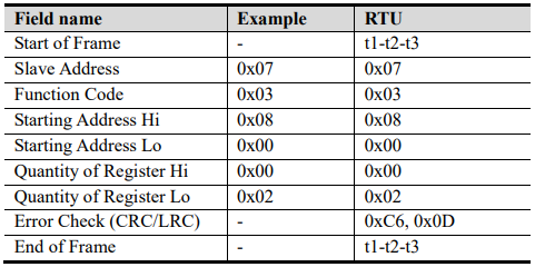
This function code is used to read the contents of a contiguous block of holding registers in a remote device. The Request PDU specifies the starting register address and the number of registers.
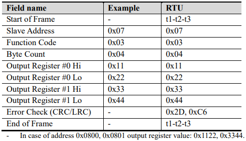
The register data in the response message are packed as two bytes per register, with the binary contents right justified within each byte. For each register, the first byte contains the high order bits and the second contains the low order bits.
Request
Response
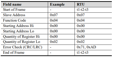
6.2.4. 4 (0x04) Read Input Registers
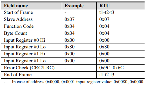
This function code is used to read from 1 to approx. 125 contiguous input registers in a remote device. The Request PDU specifies the starting register address and the number of registers. The register data in the response message are packed as two bytes per register, with the binary contents right justified within each byte. For each register, the first byte contains the high order bits and the second contains the low order bits.
Request
Response