
6. MODBUS INTERFACE
6.1. MODBUS Transmission Mode
Two different serial transmission modes are defined: The RTU mode and the ASCII mode. It defines the bit contents of message fields transmitted serially on the line. It determines how information is packed into the message fields and decoded.
6.1.1. RTU Transmission Mode
When devices communicate on a MODBUS serial line using the RTU (Remote Terminal Unit) mode, each 8–bit byte in a message contains two 4–bit hexadecimal characters. The main advantage of this mode is that its greater character density allows better data throughput than ASCII mode for the same baud rate. Each message must be transmitted in a continuous stream of characters.

6.1.2. ASCII Transmission Mode
When devices are setup to communicate on a MODBUS serial line using ASCII (American Standard Code for Information Interchange) mode, each 8–bit byte in a message is sent as two ASCII characters. This mode is used when the physical communication link or the capabilities of the device does not allow the conformance with RTU mode requirement regarding timers management.

6.2. Supported MODBUS Function Codes
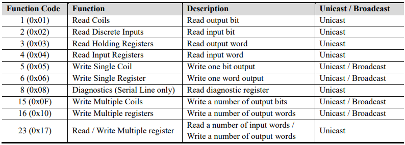
6.2.1. 1 (0x01) Read Coils
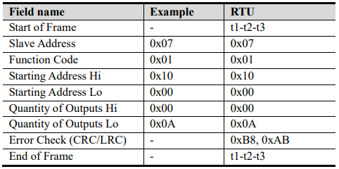
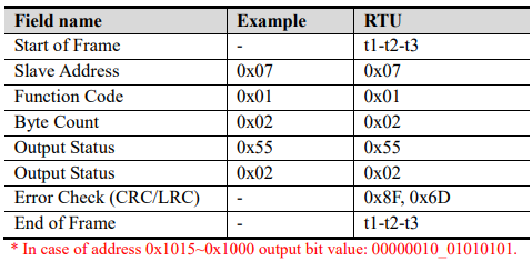
This function code is used to read from 1 to 2000 contiguous status of coils in a remote device. The Request PDU specifies the starting address, i.e. the address of the first coil specified, and the number of coils. In the PDU Coils are addressed starting at zero. Therefore coils numbered 1-16 are addressed as 0-15. The coils in the response message are packed as one coil per bit of the data field. Status is indicated as 1= ON and 0= OFF.
Request
Response
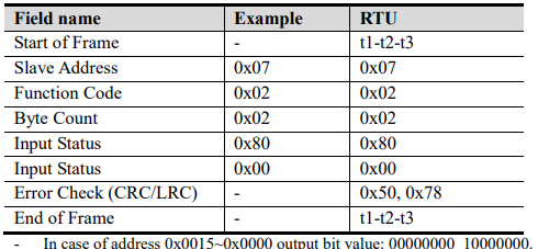
6.2.2. 2 (0x02) Read Discrete Inputs
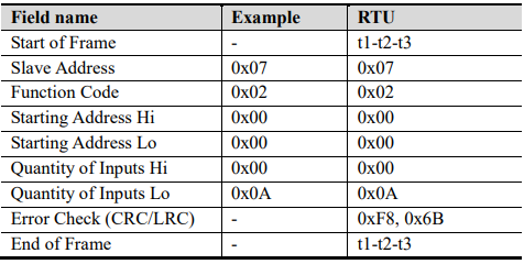
This function code is used to read from 1 to 2000 contiguous status of discrete inputs in a remote device. The Request PDU specifies the starting address, i.e. the address of the first input specified, and the number of inputs. In the PDU Discrete Inputs are addressed starting at zero. Therefore Discrete inputs numbered 1-16 are addressed as 0-15. The discrete inputs in the response message are packed as one input per bit of the data field. Status is indicated as 1= ON; 0= OFF.
Request
Response
6.2.3. 3 (0x03) Read Holding Registers
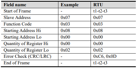
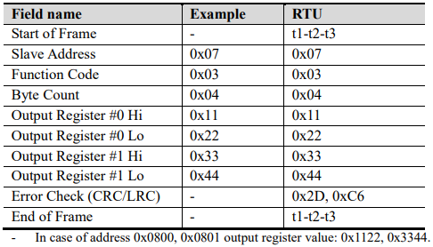
This function code is used to read the contents of a contiguous block of holding registers in a remote device. The Request PDU specifies the starting register address and the number of registers.
The register data in the response message are packed as two bytes per register, with the binary contents right justified within each byte. For each register, the first byte contains the high order bits and the second contains the low order bits.
Request
Response
6.2.4. 4 (0x04) Read Input Registers
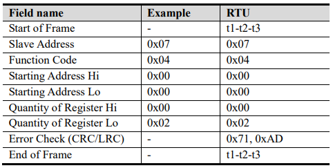
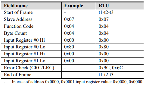
This function code is used to read from 1 to approx. 125 contiguous input registers in a remote device. The Request PDU specifies the starting register address and the number of registers. The register data in the response message are packed as two bytes per register, with the binary contents right justified within each byte. For each register, the first byte contains the high order bits and the second contains the low order bits.
Request
Response
6.2.5. 5 (0x05) Write Single Coil
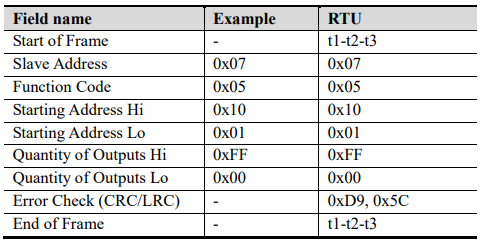
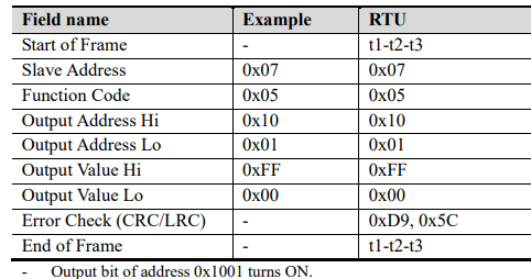
This function code is used to write a single output to either ON or OFF in a remote device. The requested ON/OFF state is specified by a constant in the request data field. A value of FF 00 hex requests the output to be ON. A value of 00 00 requests it to be OFF. All other values are illegal and will not affect the output.
Request
Response
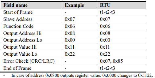
6.2.6. 6 (0x06) Write Single Register
Request
Response
6.2.7. 8 (0x08) Diagnostics
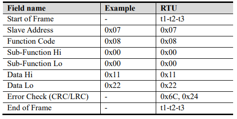
MODBUS function code 08 provides a series of tests for checking the communication system between a client (Master) device and a server (Slave), or for checking various internal error conditions within a server. The function uses a two–byte sub-function code field in the query to define the type of test to be performed. The server echoes both the function code and sub-function code in a normal response. Some of the diagnostics cause data to be returned from the remote device in the data field of a normal response.
Request
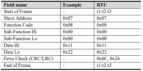
Response
Sub-function 0x0000(0) Return Query Data
The data passed in the request data field is to be returned (looped back) in the response. The entire response message should be identical to the request.

Sub-function 0x0001(1) Restart Communications Option
The remote device could be initialized and restarted, and all of its communications event counters are cleared. Especially, data field 0x55AA makes the remote device to restart with factory default setup of EEPROM

Sub-function 0x000A(10) Clear Counters and Diagnostic Register
The goal is to clear all counters and the diagnostic register. Counters are also cleared upon power–up.

Sub-function 0x000B(11) Return Bus Message Count
The response data field returns the quantity of messages that the remote device has detected on the
communications system since its last restart, clear counters operation, or power–up

Sub-function 0x000C(12) Return Bus Communication Error Count
The response data field returns the quantity of CRC errors encountered by the remote device since its last restart, clear counters operation, or power–up.

Sub-function 0x000D(13) Return Bus Exception Error Count
The response data field returns the quantity of MODBUS exception responses returned by the remote device since its last restart, clear counters operation, or power–up.
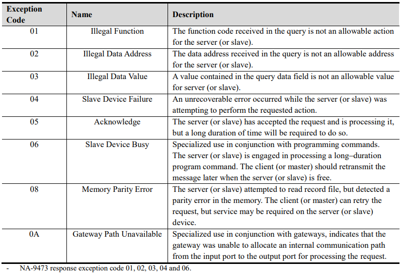
Exception responses are described and listed in section 6.2.11.

Sub-function 0x000E(14) Return Slave Message Count
The response data field returns the quantity of messages addressed to the remote device, or broadcast, that the remote device has processed since its last restart, clear counters operation, or power–up.

Sub-function 0x000F(15) Return Slave No Response Count
The response data field returns the quantity of messages addressed to the remote device for which it has returned no response (neither a normal response nor an exception response), since its last restart, clear counters operation, or power–up.

Sub-function 0x0064(100) Return Slave MODBUS, FnBus Status
The response data field returns the status of MODBUS and FnBus addressed to the remote device. This status values are identical with status 1word of input process image. Refer to 5.3.1.

Sub-function 0x0065(101) Return Slave MODBUS, Error Count
The response data field returns the quantity of watchdog error addressed to the remote device since its last restart, clear counters operation, or power–up.

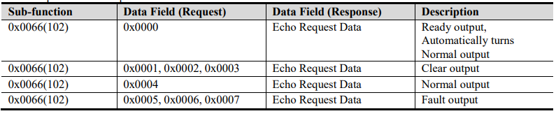
Sub-function 0x0066(102) Change Slave IO Output Status
The sub-function with data fields is to clear watchdog counter and change IO output status. This may be used to simulate clear output and fault output.
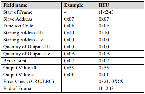
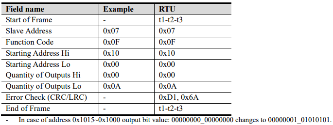
6.2.8. 15 (0x0F) Write Multiple Coils
This function code is used to force each coil in a sequence of coils to either ON or OFF in a remote device. The Request PDU specifies the coil references to be forced. Coils are addressed starting at zero. A logical '1' in a bit position of the field requests the corresponding output to be ON. A logical '0' requests it to be OFF.
The normal response returns the function code, starting address, and quantity of coils forced.
Request
Response
6.2.9. 16 (0x10) Write Multiple Registers
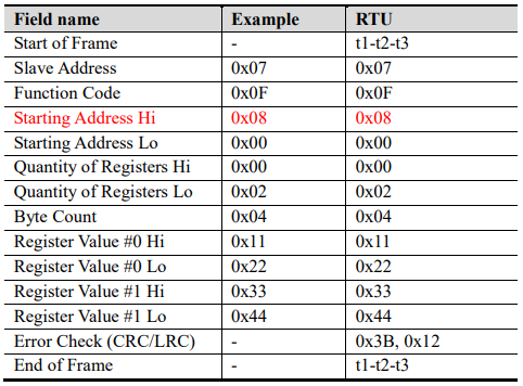
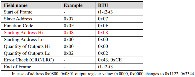
This function code is used to write a block of contiguous registers (1 to approx. 120 registers) in a remote device. The requested written values are specified in the request data field. Data is packed as two bytes per register. The normal response returns the function code, starting address, and quantity of registers written.
Request
Response
6.2.10. 23 (0x17) Read/Write Multiple Registers
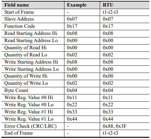
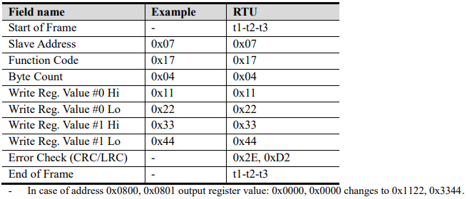
This function code performs a combination of one read operation and one write operation in a single MODBUS transaction. The write operation is performed before the read. The request specifies the starting address and number of holding registers to be read as well as the starting address, number of holding registers, and the data to be written. The byte count specifies the number of bytes to follow in the write data field. The normal response contains the data from the group of registers that were read. The byte count field specifies the quantity of bytes to follow in the read data field.
Request
Response
6.2.11. Error Response
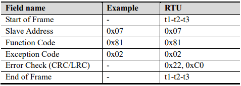
In an exception response, the server sets the MSB of the function code to 1. This makes the function code value in an exception response exactly 80 hexadecimal higher than the value would be for a normal response.
Exception Response Example
Exception Codes
6.3. MODBUS Special Register Map
The special register map can be accessed by function code 3, 4, 6 and 16. Also the special register map must be accessed by read/write of every each address (one address).
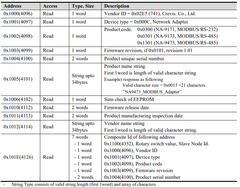
6.3.1. Adapter Identification Special Register (0x1000, 4096)
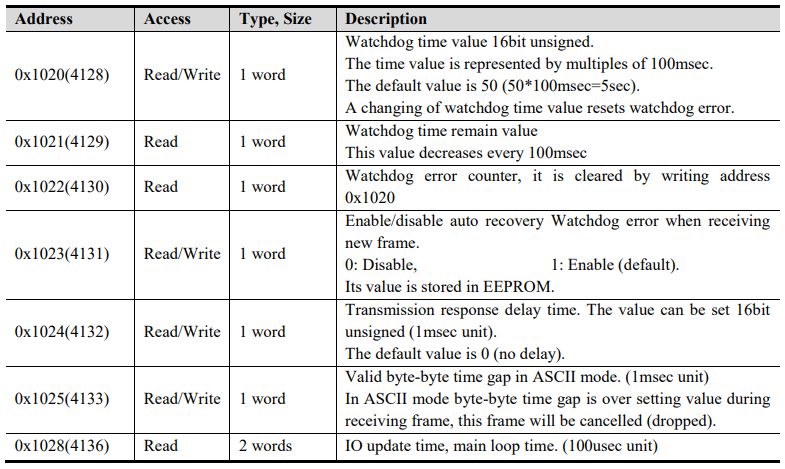
6.3.2. Adapter Watchdog Time, other Time Special Register (0x1020, 4128)
A watchdog timer can be configured for timeout periods up to 65535(1unit=100msec). The Watchdog timer will timeout (timer decreased, reached 0) if MODBUS operation to the slave node does not occur over the configured watchdog value, then the slave adapter forces that slot output value is automatically set to user-configured fault actions and values.
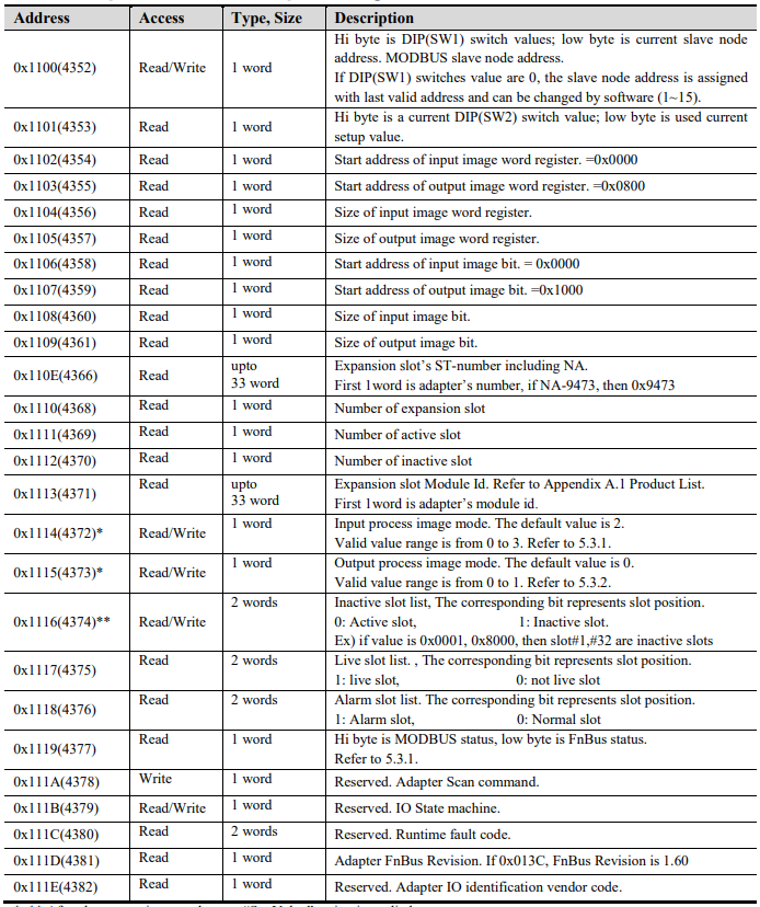
6.3.3. Adapter Information Special Register (0x1100, 4352)
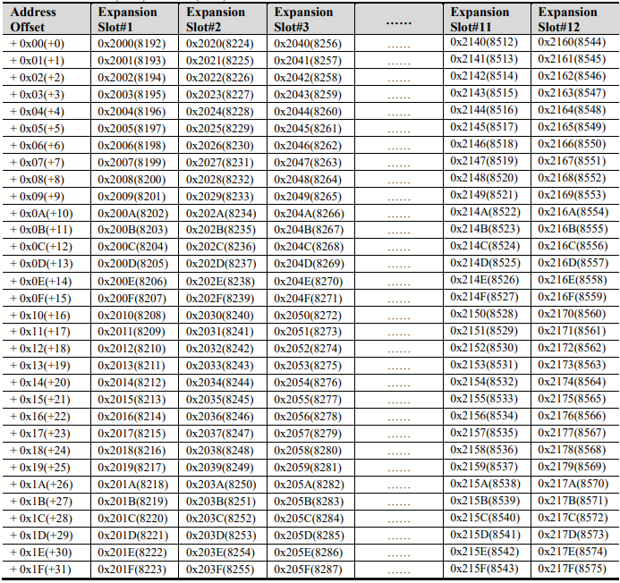
6.3.4. Expansion Slot Information Special Register (0x2000, 8192)
Each expansion slot has 0x20(32) address offset and same information structure.
Slot#1 0x2000(8192) ~0x201F (8223)
Slot#2 0x2020(8224) ~0x203F (8255)
Slot#3 0x2040(8256) ~0x205F (8287)
Slot#4 0x2060(8288) ~0x207F (8319)
Slot#5 0x2080(8320) ~0x209F (8351)
Slot#6 0x20A0 (8352) ~0x20BF (8383)
Slot#7 0x20C0 (8384) ~0x20DF (8415)
Slot#8 0x20E0 (8416) ~0x20FF (8447)
Slot#9 0x2100(8448) ~0x211F (8479)
Slot#10 0x2120(8480) ~0x213F (8511)
Slot#11 0x2140(8512) ~0x215F (8543)
Slot#12 0x2160(8544) ~0x217F (8575)
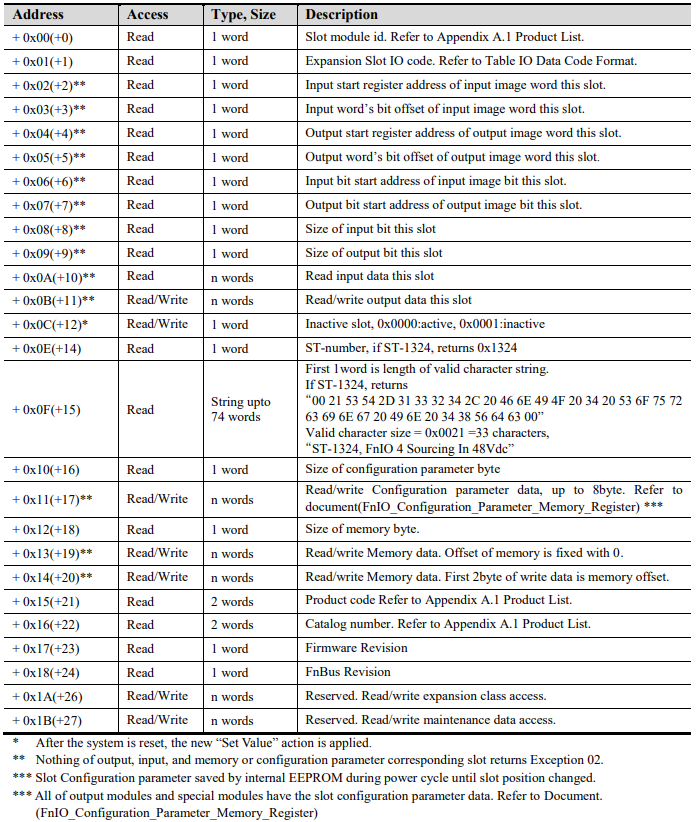
IO Data Code Format (1 word)
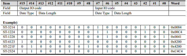
Input/output Data Type:
0 0: No I/O Data
0 1: Byte Data
1 0: Word Data
1 1: Bit Data
Input/output Data Length:
0 0 0 0 0 0 0: 0 Bit/Byte/Word
0 0 0 0 0 0 1: 1 Bit/Byte/Word
0 0 0 0 0 1 0: 2 Bit/Byte/Word
0 0 0 0 0 1 1: 3 Bit/Byte/Word
……
1 1 1 1 1 1 1: 63 Bit/Byte/Word
6.4. MODBUS Reference
MODBUS Reference Documents
http://www.modbus.org
MODBUS Tools
http://www.modbustools.com , MODBUS poll
http://www.win-tech.com , MODSCAN32