7. CANopen Control Mode
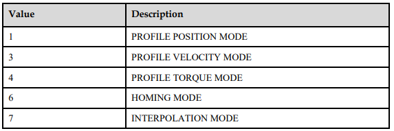
EM3A currently supports 5 control modes in CANopen DSP402:
HOMING MODE
PROFILE VELOCITY MODE
PROFILE TORQUE MODE
PROFILE POSITION MODE
INTERPOLATED POSITION MODE
7.1 Relevant Parameter of Control Mode

7.1.1 Modes_of_operation
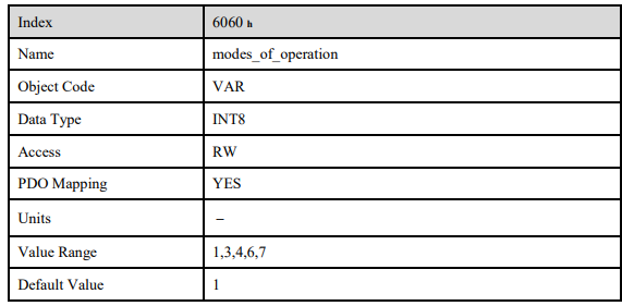
Drive control mode will be determined by parameters in modes_of_operation
7.1.2 Modes_of_operation_display
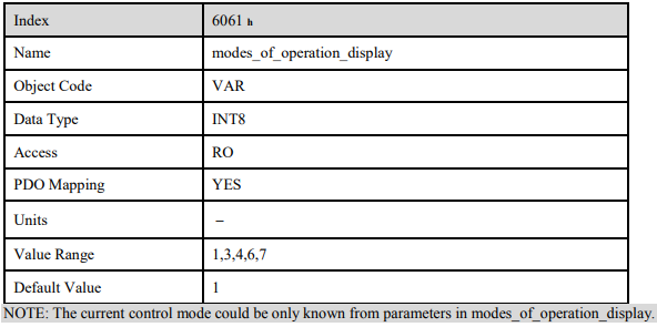
Drive current control mode could be read from parameters in modes_of_operation_display.
7.2 Homing Mode
ED3M servo drive currently supports multiple homing mode and users could choose the suitable homing mode. For example, if an incremental encoder is applied in servomotor, then homing mode of Zero impulse could be chosen and if serial encoder or resolver is applied in servomotor then Zero impulse homing mode couldn’t be selected.
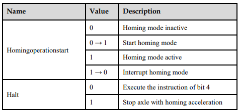
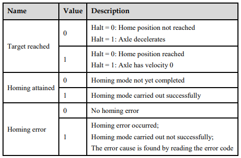
The user can determine the velocity, acceleration, and the kind of homing operation. After the servo controller has found its reference the zero position can be moved to the desired point via the object home_offset (607C h) .
7.2.1 Control Word

7.2.2 Status Word

7.2.3 Relevant parameter
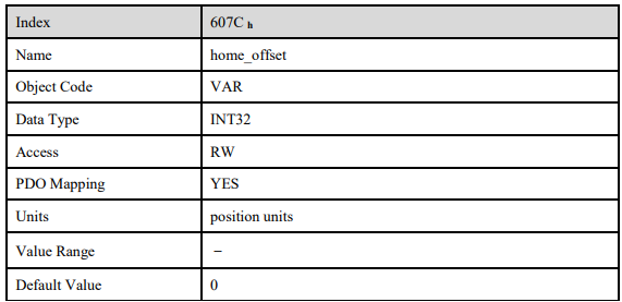
home_offset
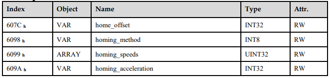
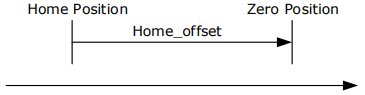
The object home_offset determines the displacement of the zero position to the limit resp. reference switch position.
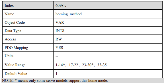
homing_method
The negative and positive limit switch, the reference switch and the (periodic) zero impulse of the angle encoder.
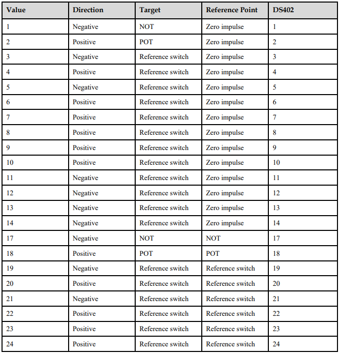
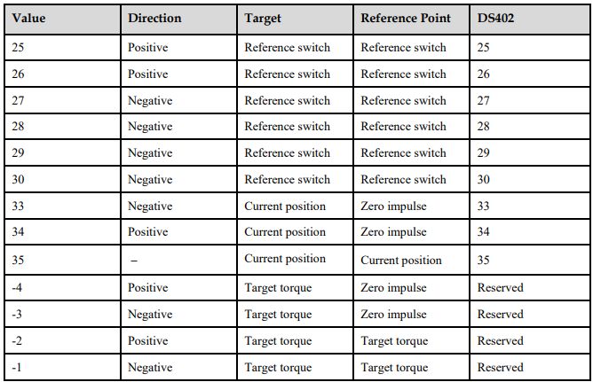
Homing method value description is as following:
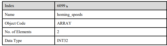
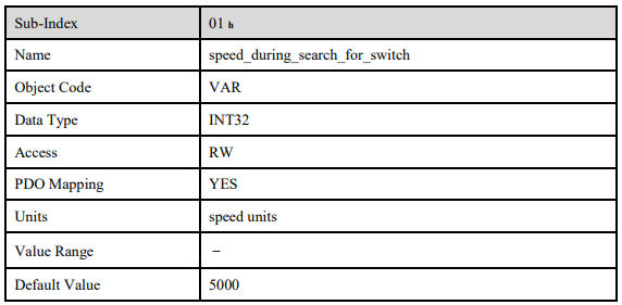
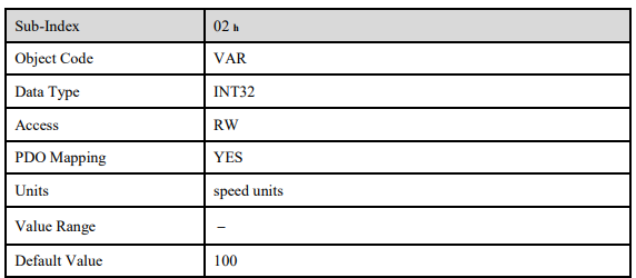
homing_speeds
There are two kinds of speeds required to find reference point, speed during search for switch and speed during search for zero.

Pn207 (stopper torque)
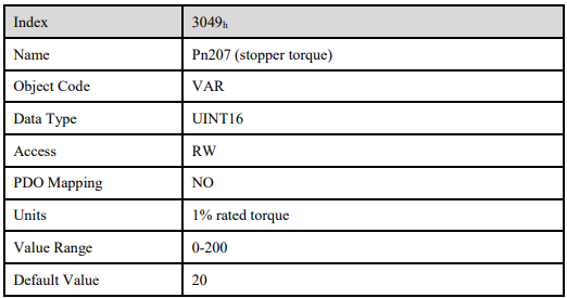
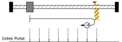
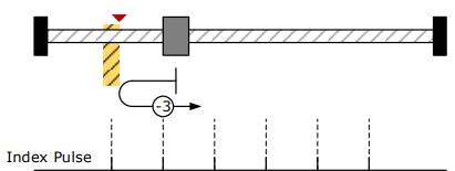
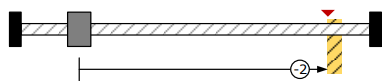
It is used for homing method -4, -3, -2, -1.When the drive hits an end so that the torque set in Pn207 is reached for the blocking time set in Pn208, movement in the opposite direction or makes the current position for the origin.
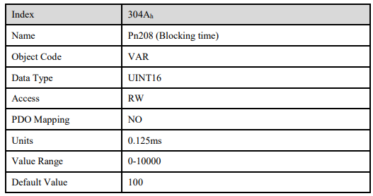
Pn208 (blocking time)
It is used for homing method -4, -3, -2, -1.When the drive hits an end so that the torque set in Pn207 is reached for the blocking time set in Pn208, movement in the opposite direction or makes the current position for the origin.
homing_acceleration
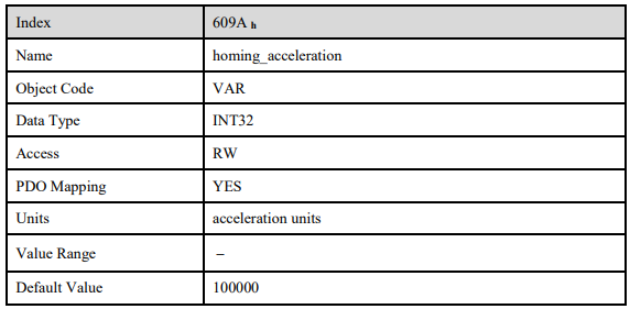
The objects homing_acceleration determine the acceleration which is used for all acceleration and deceleration operations during the search for reference.
7.2.4 Homing Sequences
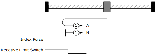
Method 1: Using egative limit switch and zero impulse evaluation
A: When homing mode is enabled, If negative limit switch N-OT=0, the drive first moves relatively quick into the negative direction until it reaches the negative limit switch. This is displayed in the diagram by the rising edge. Afterwards the drive slowly returns, and stops until reaches the falling edge.
B: When homing mode is enabled, If negative limit switch N-OT=1, the drive first moves slowly into the positve direction until reaches the falling edge
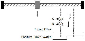
Method 2: Using positive limit switch and zero impulse evaluation
A: When homing mode is enabled, If positive limit switch P-OT=0, the drive first moves relatively quick into the positive direction until it reaches the positive limit switch. This is displayed in the diagram by the rising edge. Afterwards the drive slowly returns, and stops until reaches the falling edge.
B: When homing mode is enabled, If positive limit switch P-OT=1, the drive first moves slowly into the negative direction until reaches the falling edge.
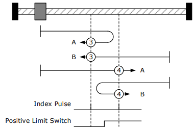
Methods 3 and 4: Using positive reference switch and zero impulse evaluation
Method 3
A: When homing mode is enabled, If positive reference switch H-S=0, the drive first moves relatively quick into the positive direction until it reaches the positive reference switch. This is displayed in the diagram by the rising edge. Afterwards the drive slowly returns, and stops until reaches the falling edge.
B: When homing mode is enabled, If positive reference switch H-S =1, the drive first moves slowly into the negative direction until reaches the falling edge.
Method 4
A: When homing mode is enabled, If positive reference switch H-S =0, the drive first moves slowly into the positive direction until reaches the rising edge.
B: When homing mode is enabled, If positive reference switch H-S=1, the drive first moves relatively quick into the negative direction until it reaches the positive reference switch. This is displayed in the diagram by the falling edge. Afterwards the drive slowly returns, and stops until reaches the rising edge.
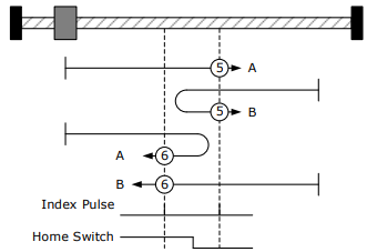
Methods 5 and 6: Using negative reference switch and zero impulse evaluation
Method 5
A: When homing mode is enabled, If negative reference switch H-S =1, the drive first moves slowly into the positive direction until reaches the zero impulse evaluation. This is displayed in the diagram by the falling edge of H-S.
B: B: When homing mode is enabled, If negative reference switch H-S=0, the drive first moves relatively quick into the negative direction until it reaches the negative reference switch This is displayed in the diagram by the rising edge. Afterwards the drive slowly returns, and stops until reaches the zero impulse evaluation. This is displayed in the diagram by the falling edge of H-S.
Method 6
A: When homing mode is enabled, If negative reference switch H-S=1, the drive first moves relatively quick into the positive direction until it reaches the negative reference switch. This is displayed in the diagram by the falling edge. Afterwards the drive slowly returns, and stops until reaches the zero impulse evaluation. This is displayed in the diagram by the rising edge of H-S.
B: When homing mode is enabled, If negative reference switch H-S =0, the drive first moves slowly into the positive direction, and stops until reaches the zero impulse evaluation. This is displayed in the diagram by the rising edge of H-S.
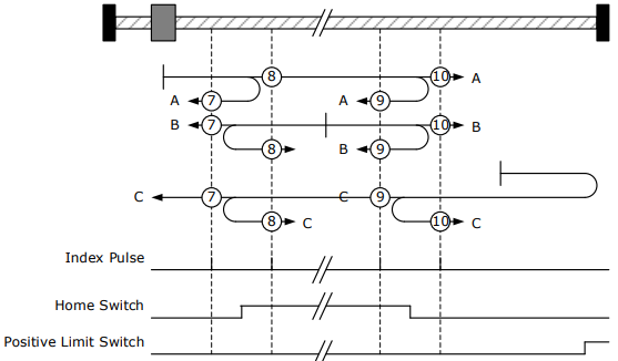
Methods 7 ~ 14 Using reference switch , limit switch and zero impulse evaluation
Methods 7~14 use the reference switch which is only active over parts of the distance.
Use positive limit switch P-OT.
If this method 7~10 is used the drive first moves relatively quick into the positive direction
− Method 7
A: When homing mode is enabled, If reference switch H-S=0, the drive first moves relatively quick into the positive direction ,not reaches positive limit switch ,until it reaches the reference switch H-S. This is displayed in the diagram by the rising edge. Afterwards the drive slowly returns, and stops until reaches the falling edge.
B: When homing mode is enabled, If reference switch H-S =1, the drive first moves slowly into the negative direction until reaches the falling edge.
C: When homing mode is enabled, If reference switch H-S=0, the drive first moves relatively quick into the positive direction , and reaches positive limit switch .The drive moves quickly into the negative direction.When reachinig the rising edge of H-S ,the drive moves slowly , and moves into the negative direction until reaches the falling edge of H-S.
− Method 8
A: When homing mode is enabled, If reference switch H-S=0, the drive first moves relatively quick into the positive direction ,not reaches positive limit switch , Afterwards the drive moves slowly into positive derection when reaches the rising edge of H-S, and stops until reaches the zero impulse evaluation.
B: When homing mode is enabled, If reference switch H-S =1, the drive first moves slowly into the negative direction until reaches the falling edge of H-S. Then moves slowly into the positive direction, stops until reaches the zero impulse evaluation. This is displayed in the diagram by the H-S rising edge.
C: When homing mode is enabled, If reference switch H-S=0, the drive first moves relatively quick into the positive direction ,reaches positive limit switch ,Afterwards the drive moves quickly into the negative derection,until reaches the rising edge of H-S. The drive slows down, and moves into into the negative derection.Reaches the falling edge of H-S,the drive returns into positive derection,until reaches the zero impulse evaluation.This is displayed in the diagram by the H-S rising edge.
− Method 9
A: When homing mode is enabled, If reference switch H-S=0, the drive first moves relatively quick into the positive direction ,not reaches positive limit switch. Afterwards the drive moves slowly into positive derection when reaches the rising edge of H-S. The drive slows down to stop until reaches the falling edge of H-S.Then drive returns slowly,and stops until reaches the zero impulse evaluation.This is displayed in the diagram by the H-S rising edge.
B: When homing mode is enabled, If reference switch H-S =1, the drive first moves slowly into the postive direction until reaches the falling edge of H-S. Then moves slowly into the negative direction, stops until reaches the zero impulse evaluation. This is displayed in the diagram by the H-S rising edge.
C: When homing mode is enabled, If reference switch H-S=0, the drive first moves relatively quick into the positive direction ,reaches positive limit switch ,Afterwards the drive moves quickly into the negative derection,until reaches the rising edge of H-S. The drive slows down, and moves into into the negative derection, and stops until reaches the zero impulse evaluation.
− Method 10
A: When homing mode is enabled, If reference switch H-S=0, the drive first moves relatively quick into the positive direction, not reaches positive limit switch. Afterwards the drive moves slowly into positive derection when reaches the rising edge of H-S.If reaches the falling edge of H-S,the drive moves slowly into positive derection until reaches the zero impulse evaluation.
B: When homing mode is enabled, If reference switch H-S =1, the drive first moves slowly into the positive direction until reaches the zero impulse evaluation. This is displayed in the diagram by the H S falling edge.
C: When homing mode is enabled, If reference switch H-S=0, the drive first moves relatively quick into the positive direction ,reaches positive limit switch ,Afterwards the drive moves quickly into the negative derection,until reaches the rising edge of H-S. The drive slows down to stop.Then the drive returns slowly to the positive derection, stops until reaches the zero impulse evaluation. This is displayed in the diagram by the H-S falling edge.
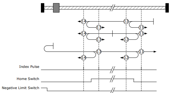
Use negative limit switch
If this method 11~14 is almost same as method 7~10, the drive first moves relatively quick into the negative direction.
Method 17~20, 23~30: Homing operation to the negative limit switch
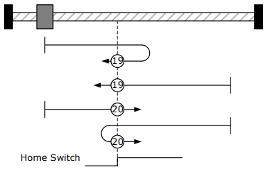
If this method is used the drive first moves relatively quick into the negative direction, until it reaches the negative limit switch. This is displayed in the diagram by the rising edge. Afterwards the drive slowly returns and searches for the exact position of the limit switch. The zero position refers to the descending edge from the negative limit switch.
Methods 21, 22 Using reference switch
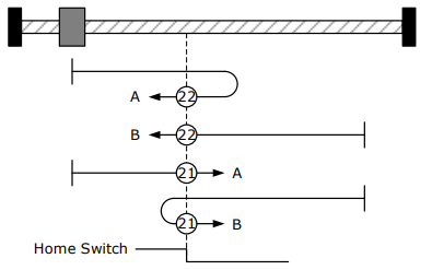
Method 21
A: When homing mode is enabled, If reference switch H-S =1, the drive first moves slowly into the positive direction until reaches the falling edge of H-S.
B: When homing mode is enabled, If reference switch H-S=0, the drive first moves relatively quick into the negative direction until it reaches the reference switch. This is displayed in the diagram by the rising edge. Then the drive returns slowly to the positive derection, stops until reaches the falling edge of the H-S.
Method 22
A: When homing mode is enabled, If reference switch H-S=1, the drive first moves relatively quick into the positive direction until it reaches the reference switch. This is displayed in the diagram by the falling edge. Afterwards the drive slowly returns, and stops until reaches the rising edge of the H-S.
B: When homing mode is enabled, If reference switch H-S =0, the drive first moves slowly into the negative direction until reaches the rising edge of the H-S.
Methods 33, 34 Using zero impulse evaluation
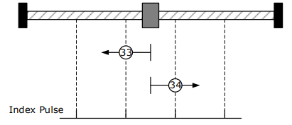
Method 33: The drive moves slowly into the negative direction,stops until reaches the zero impulse evaluation.
Method 34: The drive moves slowly into the positive direction,stops until reaches the zero impulse evaluation.
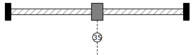
Method 35: Set current position as the homing point
Method -4 Movement in positive direction, hitting an end and reversing to travel,the target homing position is the first C pulse
In this method, the motor moves in positive direction. When it hits an end so that the torque set in Pn207 is reached for the blocking time set in Pn208, movement in the opposite direction, and the target homing position is the first C pulse.
Method -3 Movement in negative direction, hitting an end and reversing to travel,the target homing position is the first C pulse
In this method, the motor moves in negative direction. When it hits an end so that the torque set in Pn207 is reached for the blocking time set in Pn208, movement in the opposite direction, and the target homing position is the first C pulse.
Method -2:Movement in positive direction, hitting an end, makes the current position for the origin.
In this method, the motor moves in positive direction. When the drive hits an end so that the torque set in Pn207 is reached for the blocking time set in Pn208, and makes the current position for the origin
Method -1: Movement in negative direction, hitting an end, makes the current position for the origin.
In this method, the motor moves in negative direction. When the drive hits an end so that the torque set in Pn207 is reached for the blocking time set in Pn208, and makes the current position for the origin.

Notes: When starting homing on homing methed about input signal, the rotation direction of servo motor is associated with the initial status of the input signal.Changing the inicial status by inverse input on set Pn516/Pn517 if it is necessary.When using reference switch homing,I/O should be set as C:HmRef by Pn509/Pn510.
7.3 Profile Velocity Mode
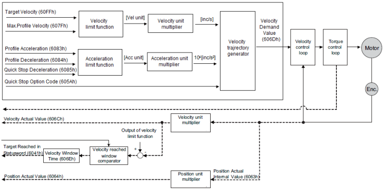
7.3.1 Flow Diagram
7.3.2 Control word
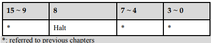

7.3.3 Status word

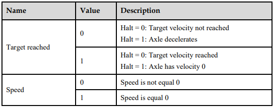

7.3.4 Relevant Parameters
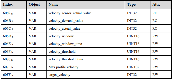
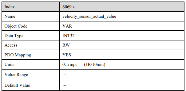
velocity_sensor_actual_value
The speed encoder is read via the object velocity_sensor_actual_value. The value is normalised in internal units. The velocity demand value can be read via this object.
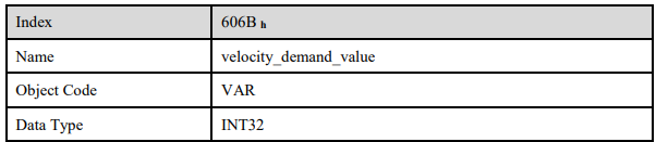
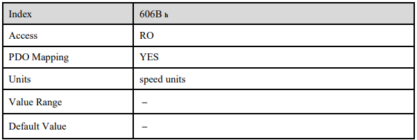
velocity_demand_value
The velocity demand value can be read via this object. The unit of this object is the unit of user’s speed unit. The velocity demand value can be read via this object
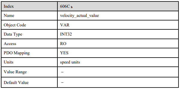
velocity_actual_value
The actual velocity value can be read via the object velocity_actual_value. The velocity demand value can be read via this object.
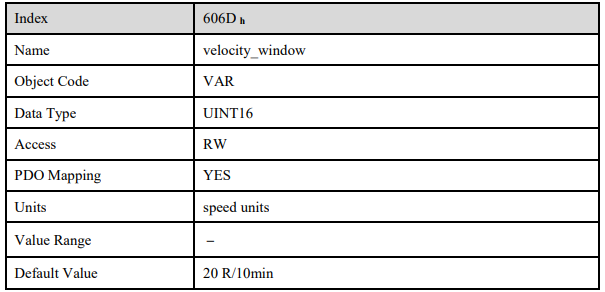
velocity_window
With the object velocity_window a tolerance window for the velocity actual value will be defined for comparing the velocity_actual_value (606C h) with the target velocity (target_velocity object 60FFh). If the difference is smaller than the velocity window (606D h) for a longer time than specified by the object velocity_window_time (606E h) bit 10 (target_reached) will be set in the object statusword.
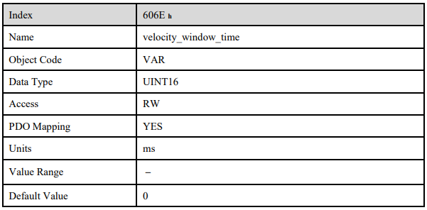
velocity_window_time
The object velocity_window_time serves besides the object 606Dh: velocity_window to adjust the window comparator.
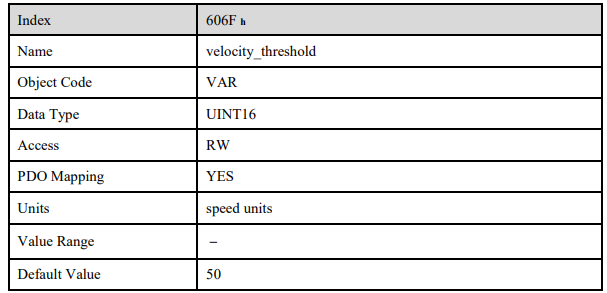
velocity_threshold
The object velocity_threshold determines the velocity underneath the axis is regarded as stationary. As soon as the velocity_actual_value exceeds the velocity_threshold longer than the velocity_threshold_time bit 12 is cleared in the statusword.
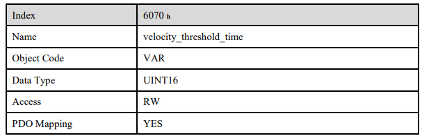
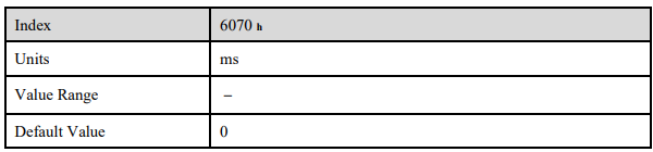
velocity_threshold_time
The object velocity_threshold determines the velocity below the axis is regarded as stationary. Its unit is ms.As soon as the velocity_actual_value exceeds the velocity_threshold longer than the velocity_threshold_time bit 12 is cleared in the statusword.
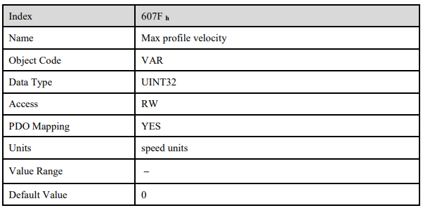
Max profile velocity
The object max profile velocity is the speed that the motor can not exceed. Its unit is the unit of customer’s speed.
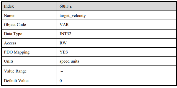
target_velocity
The object target_velocity is the setpoint for the ramp generator
7.4 Profile Torque Mode
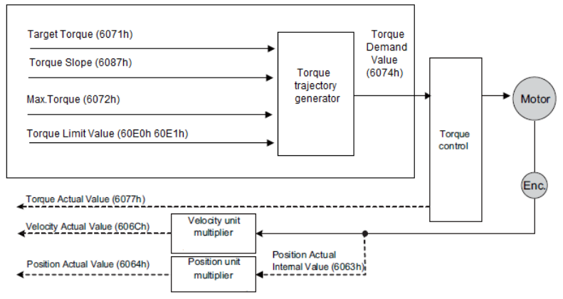
7.4.1 Flow Diagram
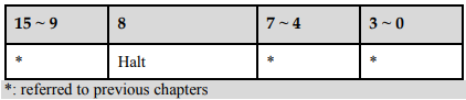
7.4.2 Control Word

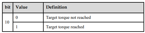
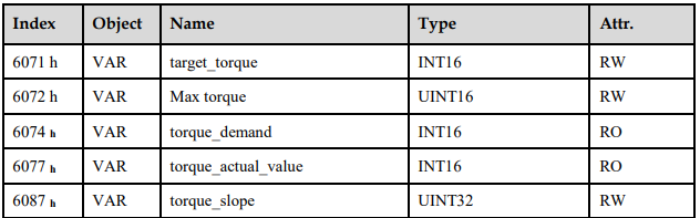
7.4.4 Relevant Parameters
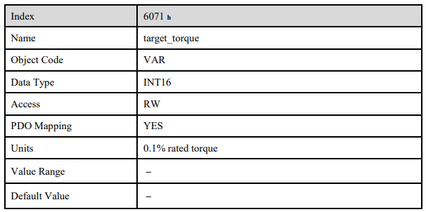
target_torque
The torque command can be sent via target_torque. Unit: 0.1% rated torque.
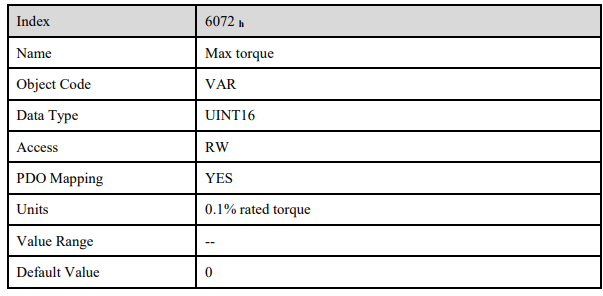
Max torque
The object max torque is the torque that the motor can not exceed. Unit: 0.1% rated torque.
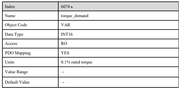
torque_demand
The output of the torque command generator.The driver generates the command according to the value of Target_Torque and Torque_Slope.
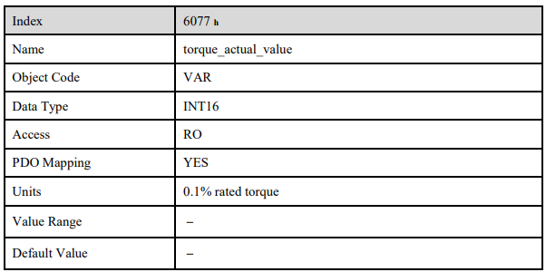
torque_actual_value
The torque output can be read via torque_actual_value. Unit: 0.1% rated torque
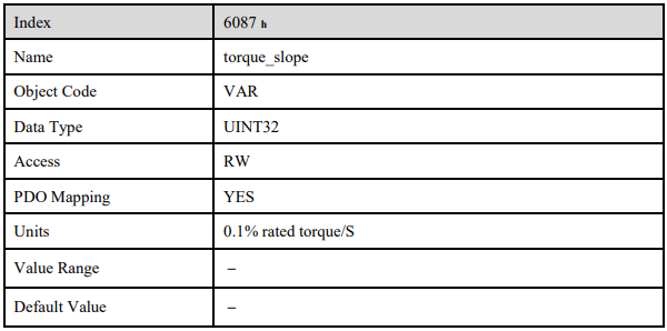
torque_slope
The speed of variational torque command can be set via torque_slope. Unit: 0.1% rated torque/S.
7.5 Profile Position Mode
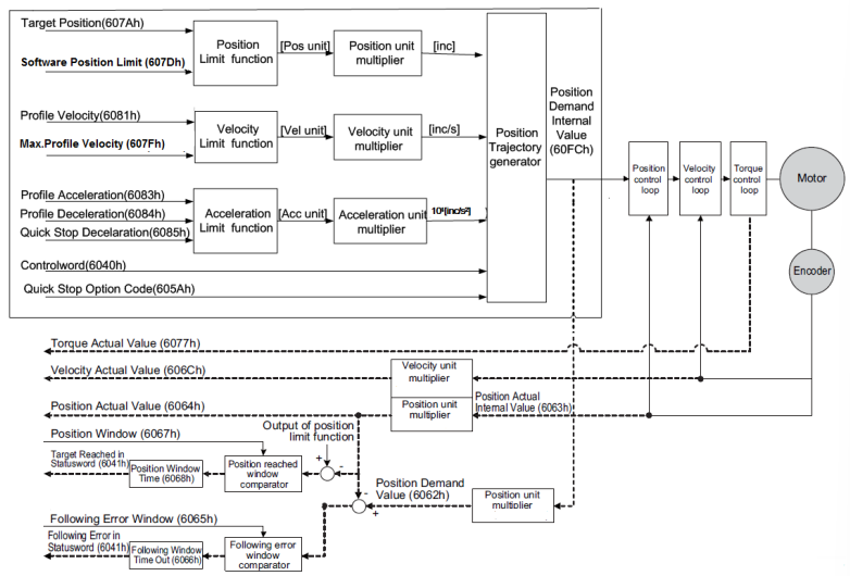
7.5.1 Flow diagram
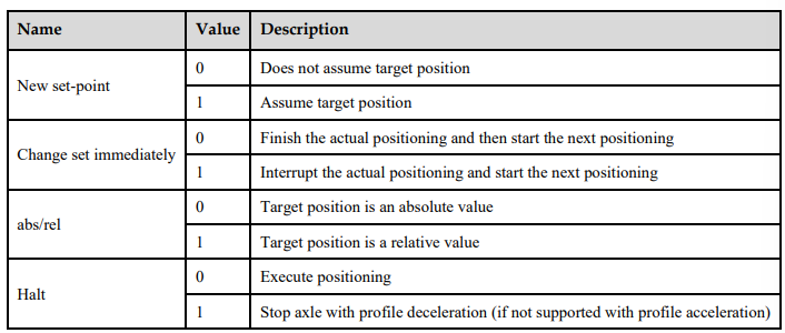
7.5.2 Control Word

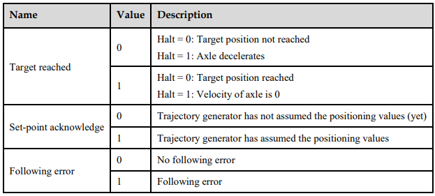
7.5.3 Status word

7.5.4 Relevant Parameters
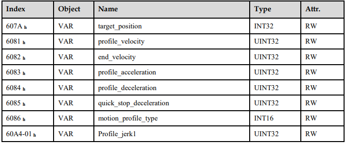
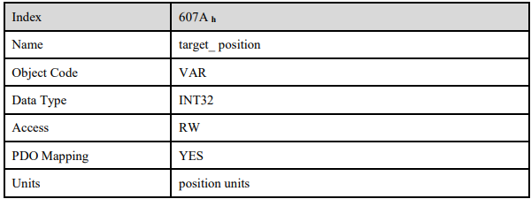
target_position
The object target_position determines the destination the servo controller moves to. The target position (target_position) is interpreted either as an absolute or relative position. This depends on bit 6 (relative) of the object control word.

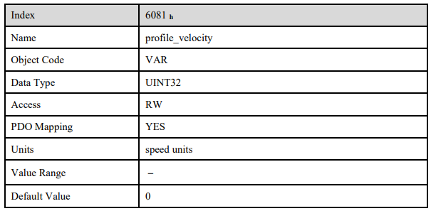
profile_velocity
The object profile_velocity specifies the speed that usually is reached during a positioning motion at the end of the acceleration ramp. The object profile_velocity is specified in speed_units.
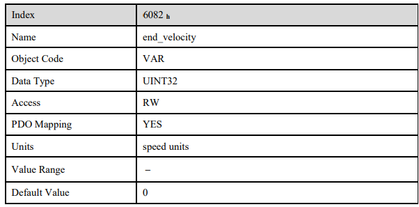
end_velocity
The object end_velocity defines the speed at the target position (target_position). Usually this object has to be set to zero so that the controller stops when it reaches the target position. For gapless sequences of positionings a value unequal zero can be set.
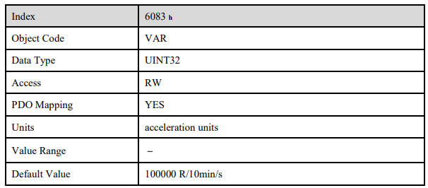
profile_acceleration
The object profile_acceleration determines the maximum acceleration used during a positioning motion. It is specified in user specific acceleration units (acceleration_units).

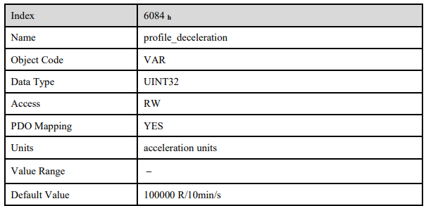
profile_deceleration
The object profile_deceleration specifies the maximum deceleration used during a positioning motion.
This object is specified in the same units as the object profile_acceleration.
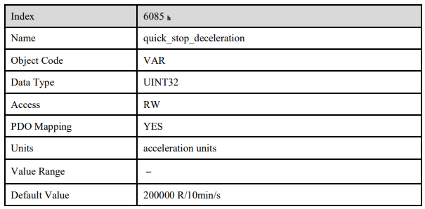
quick_stop_deceleration
The object quick_stop_deceleration determines the deceleration if a Quick Stop will be executed.
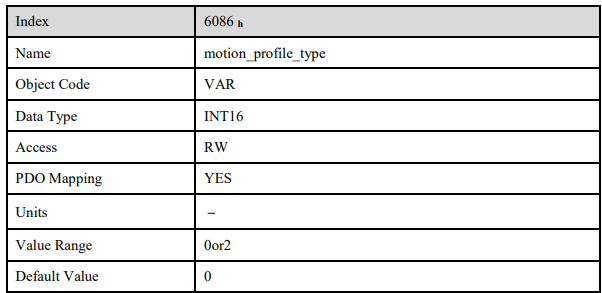
motion_profile_type
The object motion_profile_type is used to select the kind of speed profile. At present only a linear trpezia profile (set as 0) and a stable S linear jerk profile are available (set as 2).
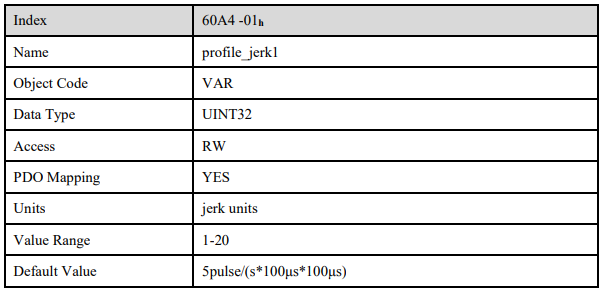
profile_jerk1
Profile_jerk1 is used to set the jerk of speed profile. The value is more smaller,the speed changing is more smooth.
7.5.5 Function description
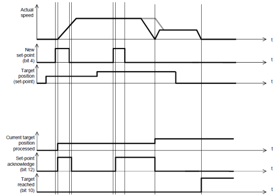
When the speed profile is trapezia (motion_profile_type=0),two different ways to apply target positions to the servo controller are supported.
Single-Step Set
After reaching the target_position the servo controller signals this status to the host by the bit target_reached (Bit 10 of controlword) and then receives a new setpoint. The servo controller stops at the target_position before starting a move to the next setpoint.
When moving to a setpoint, the servo controller signals a new setpoint by the bit target_reached (Bit 4 of controlword).Than the servo drive will move to the new setpoint.
Multi-Step Set
After reaching the target_position the servo controller signals this status to the host by the bit target_reached (Bit 10 of controlword) and then receives a new setpoint. The servo controller stops at the target_position before starting a move to the next setpoint.
These Two methods are controlled by the bit4 and bit5 in the object controlword and set_point_acknowledge in the object statusword. These bits are in a request-response relationship. So it is possible to prepare one positioning job while another job is still running.
Single-Step Setting Procedure
1. At first set NMT as Operational and control mode parameter (6061h) as 1.
2. At first the positioning data (target_position: 607A h , profile_velocity, end_velocity and profile_acceleration) are transferred to the servo controller.
3. The host can start the positioning motion by setting the bit4 (new_set_point) in the controlword as 1, bit5 (change_set_immediately) as 1 and bit6 as absolute or referential type according to target position type (absolute or referential).
4. This will be acknowledged by the servo controller by setting the bit set_point_acknowledge in the statusword when the positioning data has been copied into the internal buffer. Motion could be started now.
5. When the target is reached, drive will be acknowledged by bit 10 (target_reached) in status word. And then it will run gapless according to program or accept a new target position.
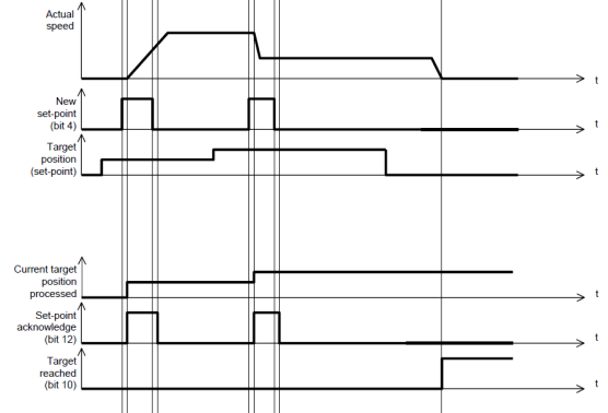
Multi-Step Setting Procedure
1. At first set NMT as Operational and control mode parameter (6061h) as 1.
2. At first the positioning data (target_position: 607Ah, profile_velocity, end_velocity and profile_acceleration) are transferred to the servo controller.
3. The host can start the positioning motion by setting the bit4 (new_set_point) in the controlword as 1, bit5 (change_set_immediately) as 0 and bit6 as absolute or referential type according to target position type (absolute or referential).
4. This will be acknowledged by the servo controller by setting the bit set_point_acknowledge in the statusword when the positioning data has been copied into the internal buffer. Motion could be started now.
5. Second positioning data (target_position: 607Ah, profile_velocity, end_velocity and profile_acceleration) are transferred to the servo controller.
6. The host can start the positioning motion by setting the bit4 (new_set_point) in the controlword as 1, bit5 (change_set_immediately) as 0 and bit6 as absolute or referential type according to target position type (absolute or referential).
7. When the 1 target is reached driver will move forward to second target position. When the second target position is reached drive will be acknowledged by bit10 (target reached) in status word. And then it will be executed by program or accept another new target position.
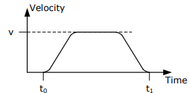
When the speed profile is S (motion_profile_type=2), only set of setpoints is available. 6083 h (profile_acceleration) limits max. acceleration. 6081h (profile_velocity) limits max.speed. 60A4-01 h (VAR Profile_jerk1) limits the jerk.now only symmetrical S linear is available.
7.6 Interplation Position Mode
7.6.1 Flow Diagram
7.6.2 Control Word

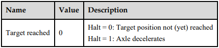
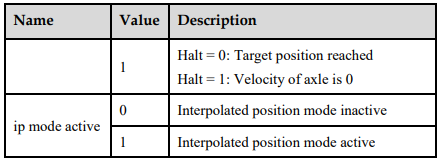
7.6.3 Status word

7.6.4 Relevant Parameters

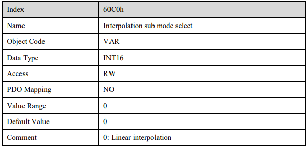
Interpolation sub mode select
Interpolation sub mode select is used to select the method of interpolation under IP control. Pronet servo drive only offers linear interpolation.
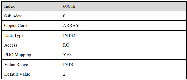
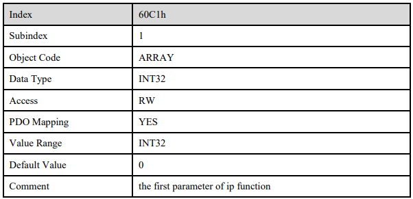
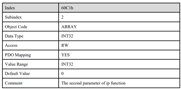
Interpolation data record
Interpolation data record is used to reserve interpolation potion data. Our servo drive’s interpolation command only uses the first data whose subindex is 1.

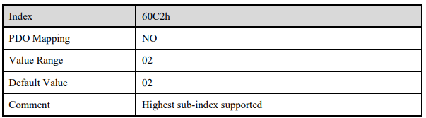
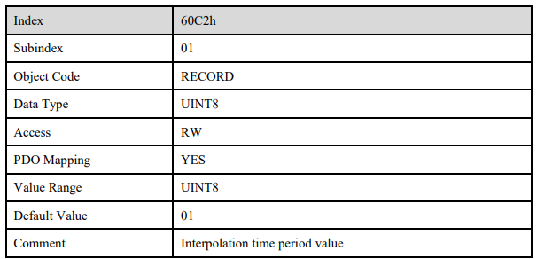
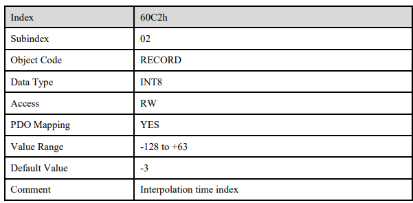
Interpolation time period
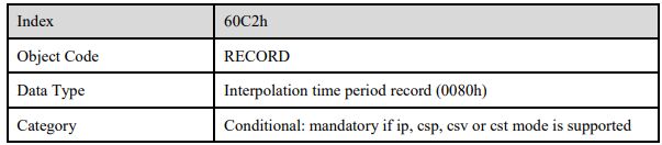
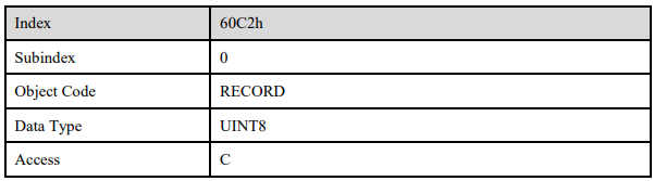
Interpolation time period is used to reserve the time data of interpolation position.
7.6.5 Function description
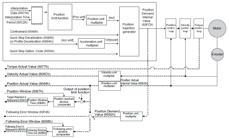
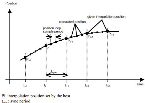
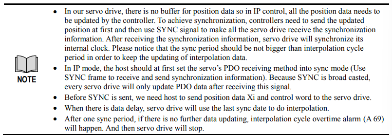
Interpolation principle in IP mode
Recommended RPDO configuration
When you use only one RPDO,
− Control word(index:6040h,subindex:0h)
− 32bit position reference (index:60C1h,subindex:01h)
When you use two RPDO
− Control word(index:6040h,subindex:0h)
− 32bit position reference (index:60C1h,subindex:01h)
Configuration process
1. Configure PDO. (RPDO1 is configured as index: 6040h, subindex: 0h, RPDO2 is configured as index 60c1h, subindex: 1h)
2. Set interpolation cycle time 2105h and 60C2, the unit is micro send (us). Please notice that both values need to be configured. For example, if the cycle time is 2ms, you need to set 2105h as 2000 and 60c2:01 as 2, 60c2:02 as -3.
3. Set sync cycle time (1006h), the unit is micro send (us)
4. Set PDO as Sync mode (Set the object dictionary (index: 1400h, subindex: 02h) as 1. Set object dictionary (index: 1401h, subindex: 02h) as 1). If sending PDO needs to be in sync mode as well, we need to set object dictionary (index: 1800h, subindex: 02h) as 1 and (index: 6060h, subindex: 0h) as 1 as well.
5. NMT starts node.
7.7 Torque limit Function
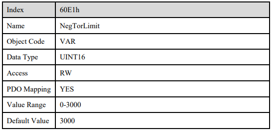
In CANopen bus mode, torque limit function is realized by 0x60E0 snd 0x60E1 as below
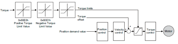
PosTorLimit(0x60E0)
PosTorLimit (0x60E0): positive torque limit, unit: 0.1% rated torque
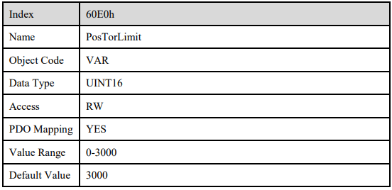
NegTorLimit(0x60E1)
NegTorLimit(0x60E1): negative torque limit,unit: 0.1% rated torque