
8. CANopen Configuration Example
The entire test below is based on three conditions:
Communication has been established correctly.
The address of the servo drive is 1.
All the message data is hexadecimal.
8.1 SDO configuration
SDO operation is to read and write parameters (0601h host sends 0581h slave sends)
Address: 3022h (Pn118) . Write 1000. And then read this parameter.
Activate the downloading process: 2B,3022,00,03E8
Message: 601(ID) 2B 22 30 00 E8 03 00 00
The servo drive should respond 60,3022,00,00,00,00,00
Message: 581(ID) 60 22 30 00 00 00 00 00
Activate the uploading: 40,3022,00,0000
Message: 601(ID) 40 22 30 00 00 00 00 00
The servo drive needs to respond: 43,3022,00,03E8
Message: 581(ID) 43 22 30 00 E8 03 00 00
8.2 PDO Configuration
RPDO mapping example: To configure two RPDO, one of which is 6040h and the other are 607A and 6081h). The slaves respond of message 581h (ID) is omitted.
RPDO 1 Mapping
RPDO 2 Mapping
And then set the transmit PDO as SYNC or Timing method. The default setting is Time method.
After configuring the PDO, if you need to activate the configuration, you need to reset the communication.

8.3 Profile Positon Mode
Step 1 At first, please mapping and configure PDO according to the example above and activate the communication.
Step 2 And then, please set the control mode.
Step 3 And then, set status machine as Operation Enable

Step 4 And then, send data by PDO
Let servo motor rotate for 5 revolutions (Set PDO1 as 6040(status word), PDO2 as 607A (position pulse number) and 6081(velocity, unit as much as 0.1rpm)
Step 5 Send RPDO2 The data is as below
Step 6 Send RPDO1 as below
----End
8.4 Two-axis interplate position mode
Step 1 At first, mapping and configure PDO. 
Step 2 Configure 1 RPDO
Step 3 Configure 2 TPDO,TPDO1: 6041h TPDO2: 6064h/606Ch

Step 4 Set Sync time. 
Step 5 Configure the PDO receiving and sending are both activated by one Sync frame.
Set 1400h
Set 1800h
Set 1801h
Step 6 Set control mode
Step 7 And then, set the status machine
Step 8 Activate the communicaiton
Step 9 Setting the second axis is the same with the first axis.
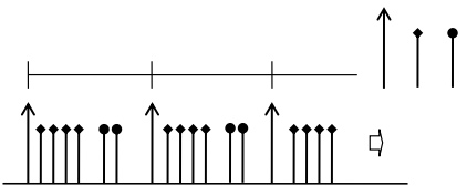
Step 10 Host sends according to the setting of test SYNC cycle(1ms): 
Step 11 And then,drive returns
Sequence diagram is as following
----End
8.5 Homing
Step 1 Set the control mode as homing control

Step 2 Set the status machine

Step 3 Send data through PDO. (Set PDO1 as 6040(status word). Set PDO2 as 607A (Position pulse number) and 6081. (Speed, unit 0.1rpm)
Set the homing method as 10rpm.

Step 4 Homing is started.

Cancel homing

----End