3. Wirings and connections
3.1 Wirings and connections for main circuit
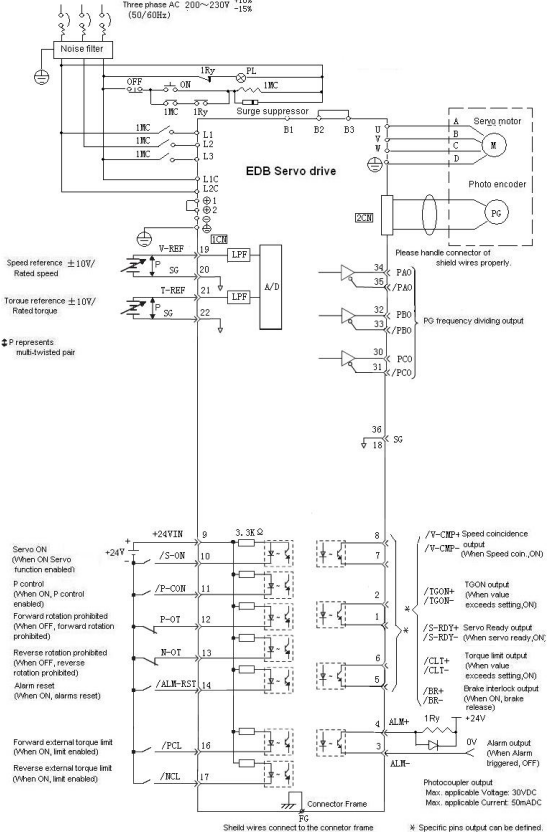
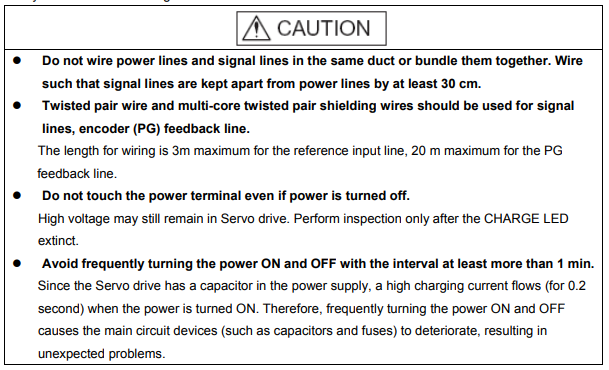
Always observe the following notes when wire or connects the circuit.
3.1.1 Names and Functions of Main Circuit Terminals
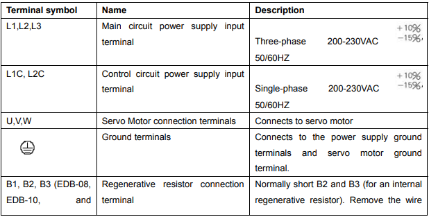
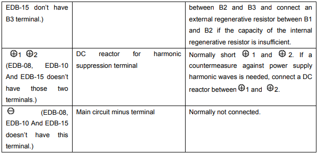
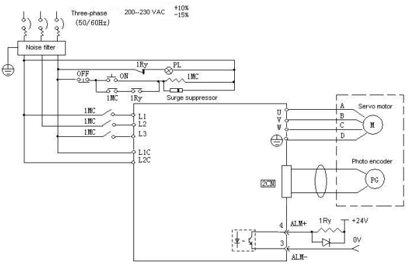
3.1.2 Typical main circuit wiring example
3.2 Input and output signal
3.2.1 Connection of input and output signals
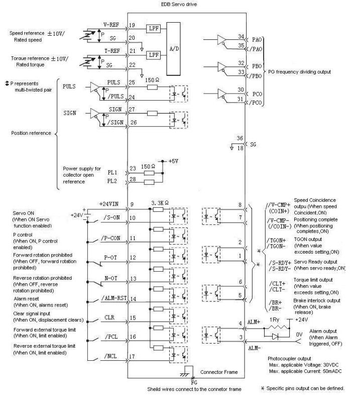
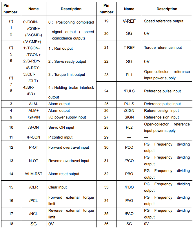
3.2.2 Terminal layout of connector 1CN
Note:
1. Do not use vacant pins for relay or other purposes.
2. Connect the shielded twisted pairs of I/O signals to connector frame.
3. Allocate and define function for pin 1CN-1, 2, 1CN-5, 6, 1CN-7, 8 according to parameter Pn053, Pn054, Pn055.
3.2.3 I/O signal names and functions
█ Input signal
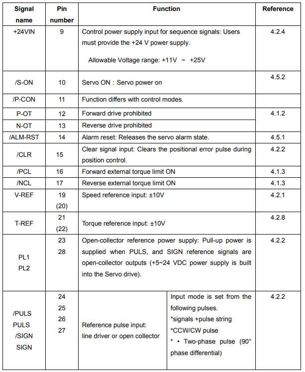
Note: 1. Pin numbers in parentheses () indicate signal grounds.
█ Output signal
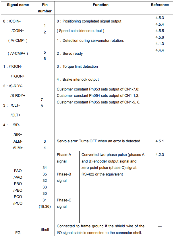
Note: 1. Pin numbers in parentheses () indicate signal grounds
3.2.4 Interface Circuit
This section shows examples of Servo drive connection to the host controller.
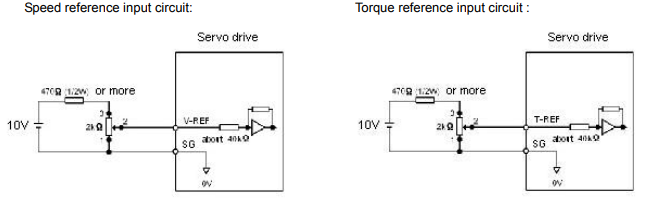
█ Interface for Analog reference Input Circuits
Analog signals are either speed or torque reference signals. The reference input resistor is about 40kΩ and Max. Allowable voltage of input signals is ±10V.
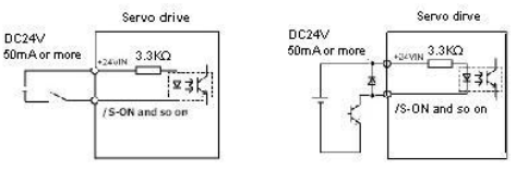
█ Sequence Input Circuit
The sequence input circuit interface connects through a relay or open-collector transistor circuit. Select a low current relay otherwise a faulty contact will result.
█ Line Driver Output Circuit
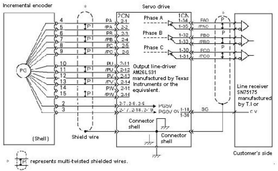
Encoder serial data converted to two-phase (phases A and B) pulse output signals (PAO, /PAO, PBO, /PBO), zero-point pulse signals (PCO, /PCO) are output via line-driver output circuits. Normally, the Servo drive uses this output circuit in speed control to comprise the position control system at the host controller. Connect the line-driver output circuit through a line receiver circuit at the host controller.
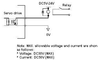
█ Sequence output circuit
Output signals of Servo alarm, Servo ready and other sequences are consist of photocoupler output circuit, please connect to relays.
3.3 wiring encoders
3.3.1 Connecting an Encoder (2CN) and Output Signals from the servodrive
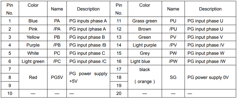
3.3.2 Encoder Connector (CN2) Terminal Layout
2CN terminals layout is as follows:
3.4 Wiring servo motor
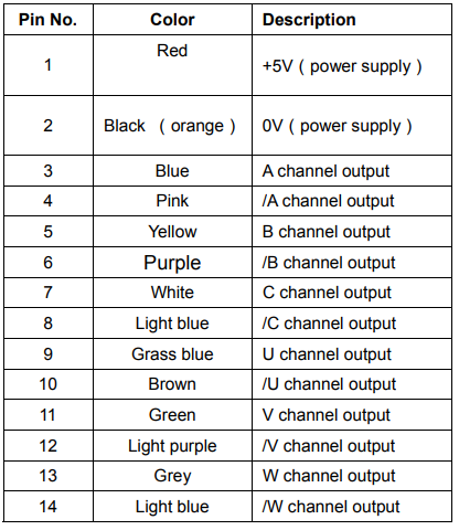
3.4.1 Encoder Connector Terminal Layout
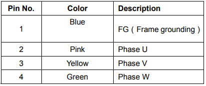
3.4.2 Dynamic power Connector Terminal layout
3.5 Typical wiring example
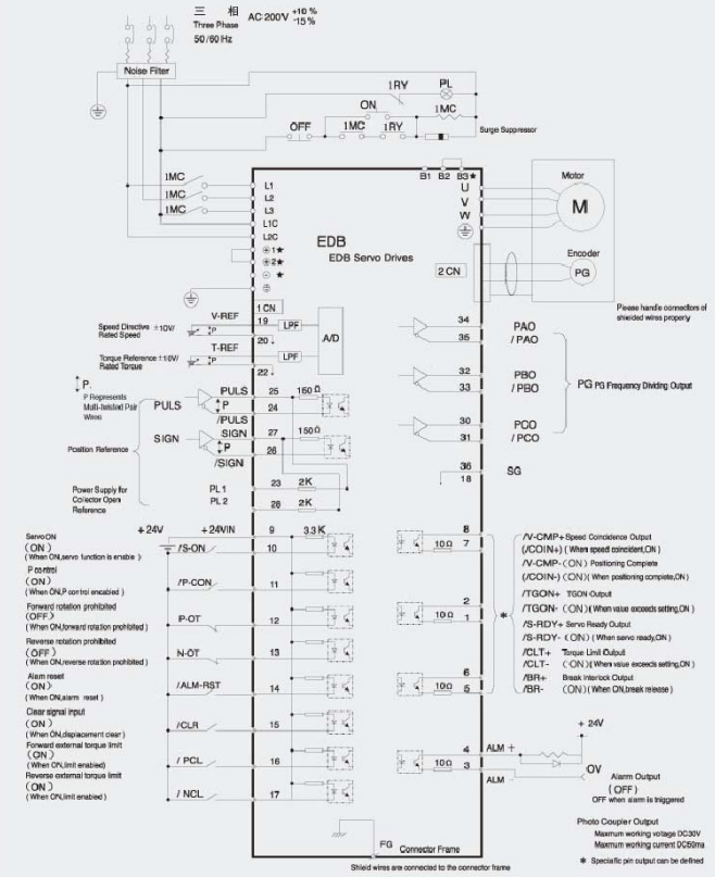
3.5.1 Position control mode
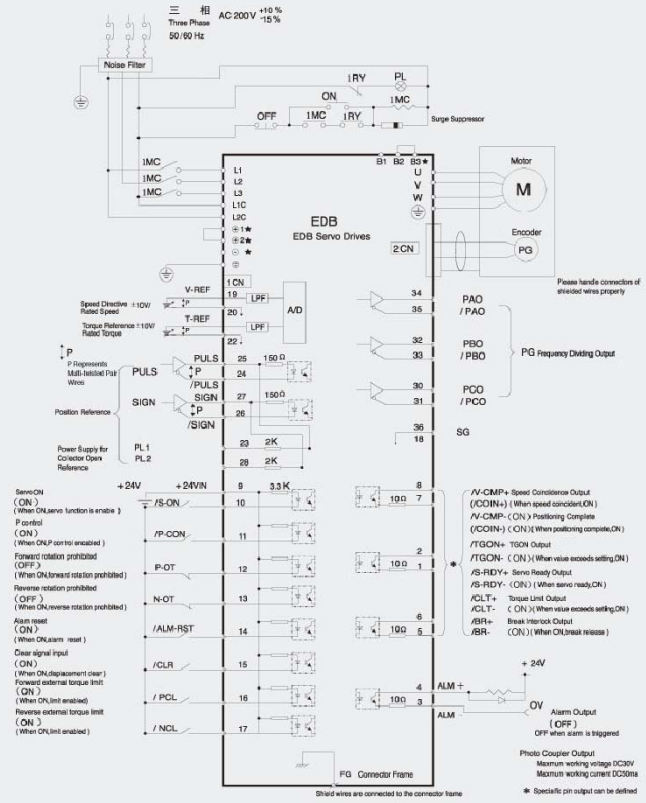
3.5.2 Speed control mode
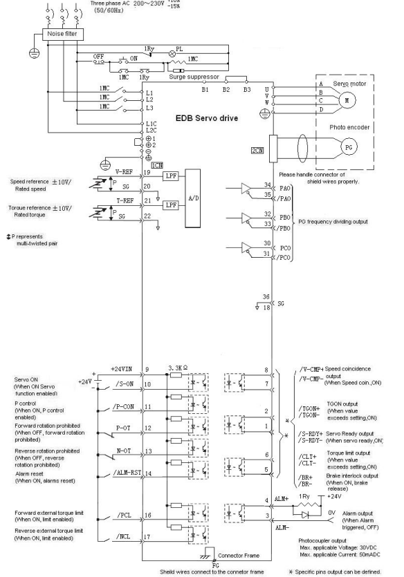
3.5.3 Torque control mode