
4. Parameter Setting and function description
4.1 Setting Parameters according to mechanical features
4.1.1 Changing the Direction of Motor Rotation
This Servo drive provides a reverse rotation mode in which the direction of rotation can be reversed without altering the servomotor wiring. With the standard setting, forward rotation is defined as counterclockwise (ccw) rotation viewed from the drive end. If reverse rotation mode is selected, the direction of motor rotation can be reversed without other conditions being changed. The direction (+/−) of axial motion is reversed and others remain unchanged.
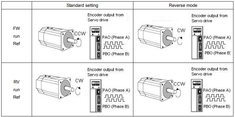
█ Setting Reverse Rotation Mode
Select the rotating direction by setting parameters below:
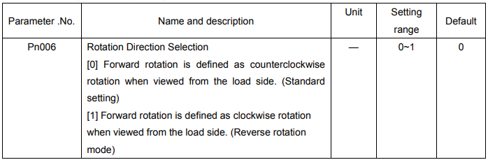
Note: After changing these parameters, turn OFF the main circuit and control power supplies and then turn them ON
4.1.2 Setting overtravel limit
The overtravel limit function forces the moving part of the machine to stop when it exceeds the movable range.
█ Using the Overtravel Limit Function
To use the overtravel limit function, connect the following overtravel limit switch input signal terminals to pins of 1CN connector correctly.

For linear motion, connect a limit switch to prevent damage to the machine.
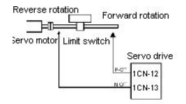
Input signal “ON/OFF” status are shown as follows:
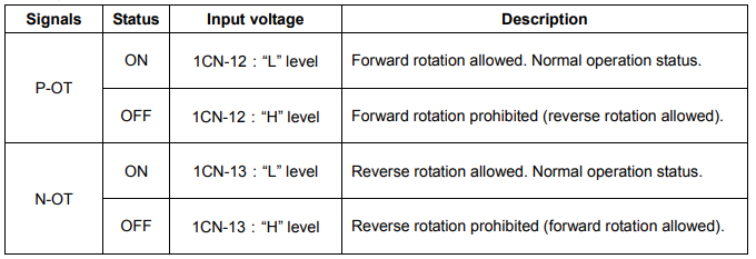
█Specifying whether Input Signals for Overtravel are to be used
Use the following parameters to specify whether input signals for overtravel is to be used. Default value is using
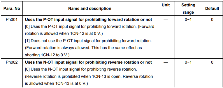

Note: When the servomotor stops due to overtravel during position control, the position error pulses
are held. A clear signal input is required to clear the error pulses.
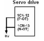
When P-OT and N-OT are not used, short wiring could be as easy as shown.
█Stop motor when overtravel occurs
Please set user constant according to the method of stopping the motor when
overtravel function is enabled.

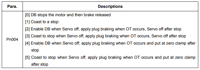
Note: Refer to 4.4.2 Dynamic brake about details of DB.

█Selecting the Motor Stop Method when Servo is OFF
The servo drive will disenable all the servo functions at following condition:
1. /S-ON input signal (1CN-10) is OFF
2. Servo alarms triggered
3. Power OFF.
Setting Pn004 to select stop modes according to the demand
4.1.3 Limiting Torque
The servo drive could use the following method to limit torque:
Grade 1: Limit the Max output torque to protect press and parts. (Limit internal torque)
Grade 2: Limit torque to move to desired position (limit external torque)
█ Grade 1 set the internal torque limit
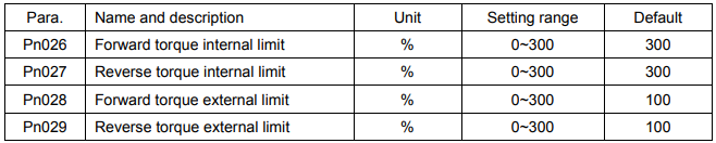
Adjust forward and reverse torque limit by setting parameters (Pn026, Pn027) for limiting torque. After setting the limit, “/CLT” will output when reach the limit value. If the torque limit is set higher than the maximum torque of the servomotor, the maximum torque of the servomotor is used.
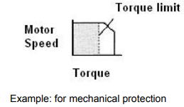
█ Grade 2 set the external torque limit
First set the torque limit of user constant (Pn028, Pn029), then enable the limit with contact input signal. Both forward and reverse torque could be set separately.
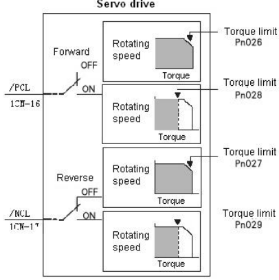



Set or use torque limit according to external contact input, “/CLT” signal will output if exceeding torque limit. Please refer to 4.2.10 Torque Limiting Using an Analog Voltage Reference for limiting torque using analog voltage output.
Note:
- Do not set the torque limit higher than Max. torque of motor.
- Too small a torque limit setting will result in insufficient torque during acceleration and deceleration.
Note:
- Please select proper mode for allocating “/PCL, /NCL” signals as torque limit input.
 “/PCL, /NCL” can’t be allocated as torque limit input in internally set speed control mode.
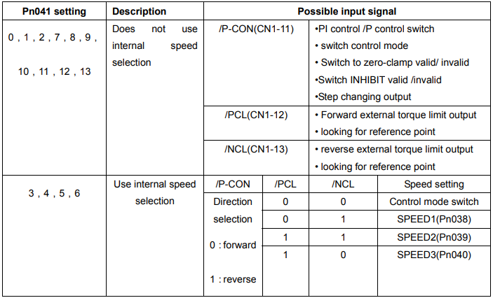
Note: 0: OFF (H level), 1: ON (L level)
Application of CLT signal:
The application of output signal /CLT is as follows:
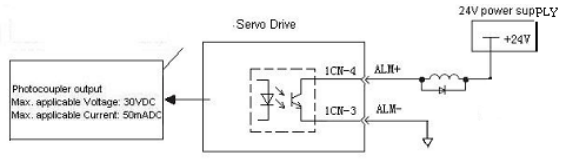

Indicates the output torque (current) of motor is limited

Please use the following user constants to define output signals and pins when using /CLT signal

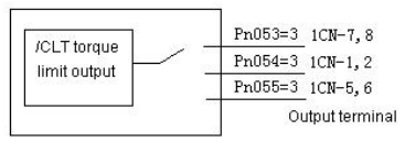
The pin definitions of Pn053, Pn054 and Pn055 parameter settings are as follows:
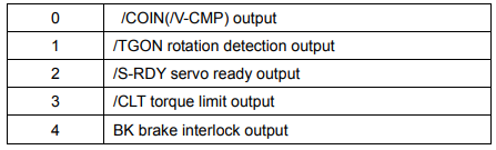
4.2 Setting Parameters According to Host Controller
4.2.1 Speed Reference
Analog reference
Input a speed reference by using the following input signal “speed reference input.”
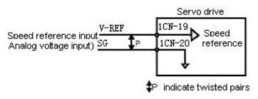

Use when in speed control (analog reference) (Pn041=0, 4, 7, 9, 10)
For general speed control, always wire the VREF and SG terminals. Motor speed is controlled in proportion to the input voltage between V-REF and SG.
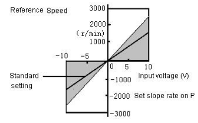
█ Standard Example
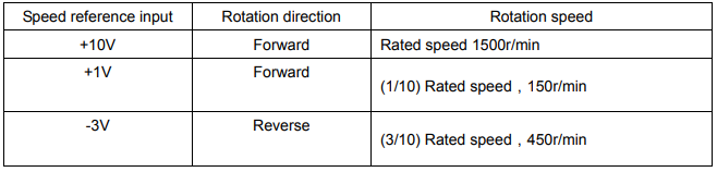
Changing “Pn-012” may modify range of speed reference. Pn-012 = 150: This setting means that 10 V is equal to rated speed (1500r/min). Specific example is as follows:
█ Example of input circuit
For noise control, always use multi-twisted cables.
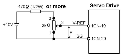
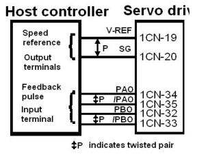
Connect V-REF and SG to speed reference output terminal when host controller is used for position control.
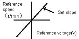
Now please refer to the specification of output voltage to adjust “Pn012”. Adjust the input gain of speed reference by setting the following parameter:

Speed reference is input from V-REF (1CN-19).Set the parameters according to the output of host controller or external circuit. The default setting is adjusted to be allowed by output voltage 10V rated speed.
Note:
- Max allowable voltage is ±10VDC speed reference input end (between 1CN-19 and 20).
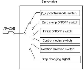
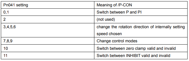
Select one of the following four control modes:

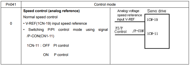
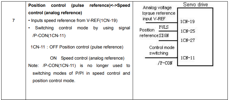
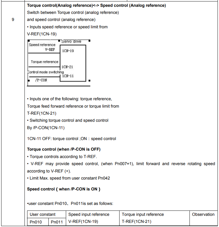
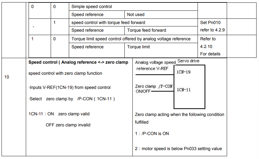
█ / P-CON signal application

Parameter speed reference
Servo motor rotates constantly according to set speed and direction of Pn048 and Pn049 under parameter speed control mode (parameter reference Pn041= 13).
4.2.2 Position reference
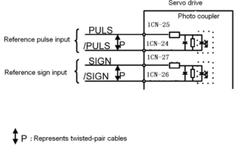
Position reference includes: reference pulse input, reference sign input and error counter clear input. There are various applications, please set the best input reference in the system established.
█ Move Reference by Pulse Input Inputs a move reference by pulse input
Position reference can correspond to the following three types of output form:
● Line driver output
● +24V Open collector output
● +12V, +5V Open collector output
Connection Example 1: Line Driver Output
Line Driver Used:
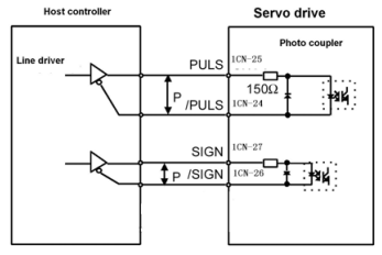
AM26LS31, SN75174 manufactured by Texas Instruments Inc., or MC3487 or equivalent.
Connection Example 2: Host controller is Open-Collector Output with 24VDC power supply
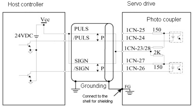
Connection Example 3: Host controller is Open-Collector Output with 12VDC or 5VDC power supply
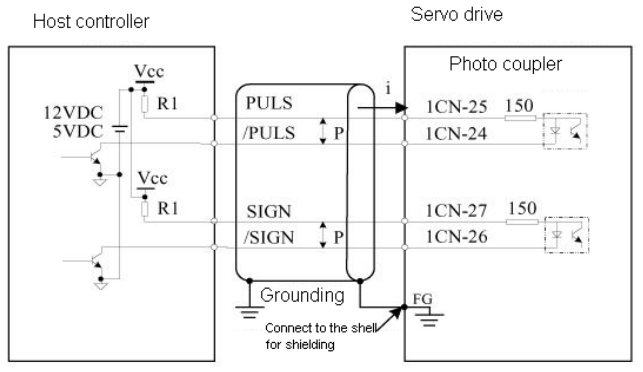
Sets the value of limiting resistor R1 according to following requirement.
Input current I=10~15mA
• When Vcc is 12 V, R1 = 510 kΩ
• When Vcc is 5 V, R1 = 180 Ω
█ Selecting the Reference Pulse Form


The motor only rotates at an angle proportional to the input pulse.
Select “reference pulse status” with the following parameters “Pn008 and Pn009”.
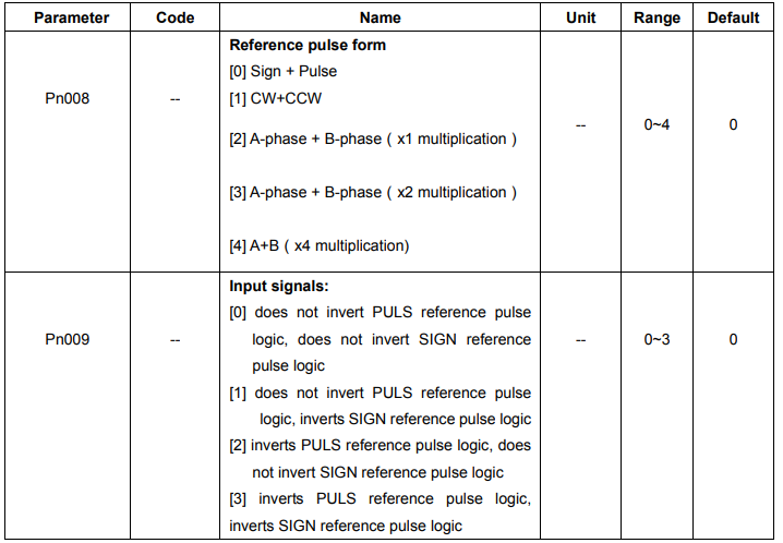
Sets the pulse form according to the host controller specifications
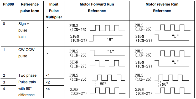
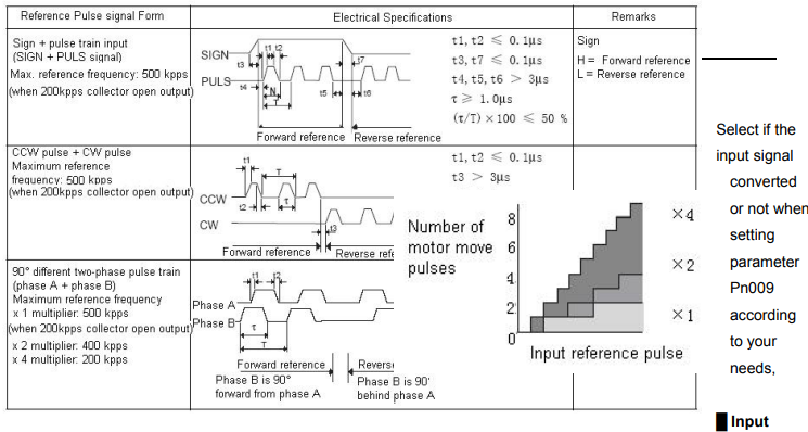
Pulse Multiply Function
When the reference form is two-phase pulse train with 90° phase difference, the input pulse multiply function can be used.
The electronic gear function can also be used to convert input pulses. Allowable Voltage Level and Timing for Reference Pulse Input