
4. Parameter Setting and function description
4.1 Setting Parameters according to mechanical features
4.1.1 Changing the Direction of Motor Rotation
This Servo drive provides a reverse rotation mode in which the direction of rotation can be reversed without altering the servomotor wiring. With the standard setting, forward rotation is defined as counterclockwise (ccw) rotation viewed from the drive end. If reverse rotation mode is selected, the direction of motor rotation can be reversed without other conditions being changed. The direction (+/−) of axial motion is reversed and others remain unchanged.
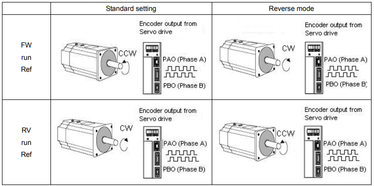
█ Setting Reverse Rotation Mode
Select the rotating direction by setting parameters below:
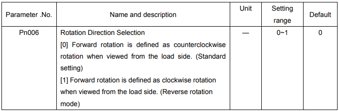
Note: After changing these parameters, turn OFF the main circuit and control power supplies and then turn them ON
4.1.2 Setting overtravel limit
The overtravel limit function forces the moving part of the machine to stop when it exceeds the movable range.
█ Using the Overtravel Limit Function
To use the overtravel limit function, connect the following overtravel limit switch input signal terminals to pins of 1CN connector correctly.

For linear motion, connect a limit switch to prevent damage to the machine.
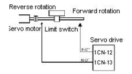
Input signal “ON/OFF” status are shown as follows:
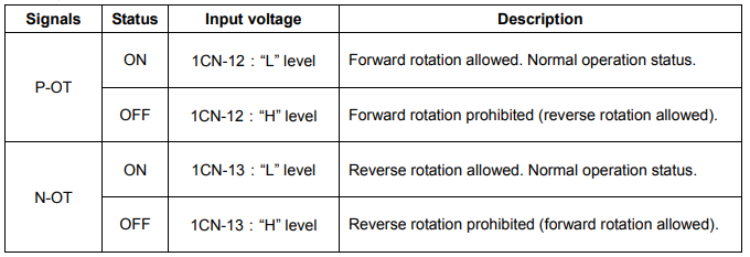
█Specifying whether Input Signals for Overtravel are to be used
Use the following parameters to specify whether input signals for overtravel is to be used. Default value is using
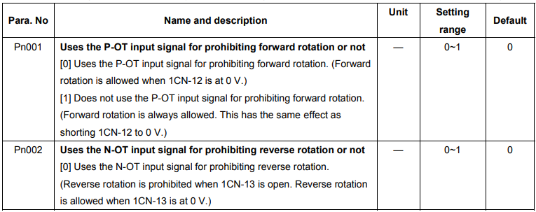

Note: When the servomotor stops due to overtravel during position control, the position error pulses
are held. A clear signal input is required to clear the error pulses.
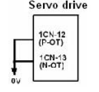
When P-OT and N-OT are not used, short wiring could be as easy as shown.
█Stop motor when overtravel occurs
Please set user constant according to the method of stopping the motor when
overtravel function is enabled.

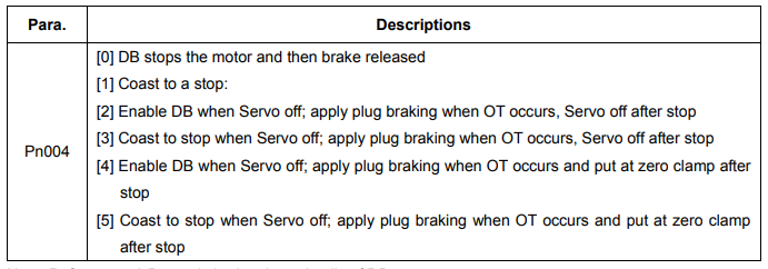
Note: Refer to 4.4.2 Dynamic brake about details of DB.

█Selecting the Motor Stop Method when Servo is OFF
The servo drive will disenable all the servo functions at following condition:
1. /S-ON input signal (1CN-10) is OFF
2. Servo alarms triggered
3. Power OFF.
Setting Pn004 to select stop modes according to the demand
4.1.3 Limiting Torque
The servo drive could use the following method to limit torque:
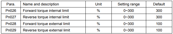
Grade 1: Limit the Max output torque to protect press and parts. (Limit internal torque)
Grade 2: Limit torque to move to desired position (limit external torque)
█ Grade 1 set the internal torque limit
Adjust forward and reverse torque limit by setting parameters (Pn026, Pn027) for limiting torque. After setting the limit, “/CLT” will output when reach the limit value. If the torque limit is set higher than the maximum torque of the servomotor, the maximum torque of the servomotor is used.
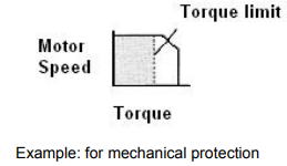
█ Grade 2 set the external torque limit
First set the torque limit of user constant (Pn028, Pn029), then enable the limit with contact input signal. Both forward and reverse torque could be set separately.
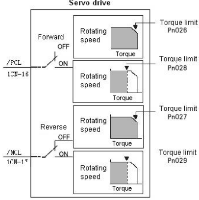



Set or use torque limit according to external contact input, “/CLT” signal will output if exceeding torque limit. Please refer to 4.2.10 Torque Limiting Using an Analog Voltage Reference for limiting torque using analog voltage output.
Note:
- Do not set the torque limit higher than Max. torque of motor.
- Too small a torque limit setting will result in insufficient torque during acceleration and deceleration.
Note:
- Please select proper mode for allocating “/PCL, /NCL” signals as torque limit input.
 “/PCL, /NCL” can’t be allocated as torque limit input in internally set speed control mode.
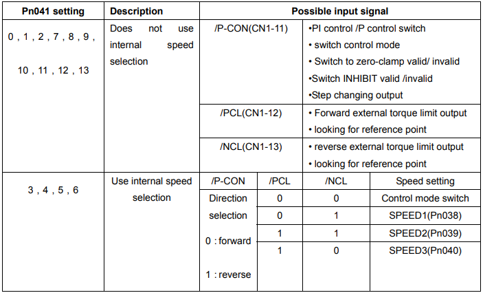
Note: 0: OFF (H level), 1: ON (L level)
Application of CLT signal:
The application of output signal /CLT is as follows:
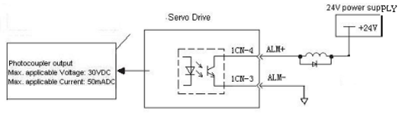

Indicates the output torque (current) of motor is limited

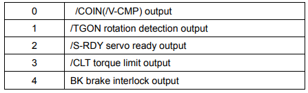
Please use the following user constants to define output signals and pins when using /CLT signal

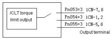
The pin definitions of Pn053, Pn054 and Pn055 parameter settings are as follows:
4.2 Setting Parameters According to Host Controller
4.2.1 Speed Reference
Analog reference
Input a speed reference by using the following input signal “speed reference input.”
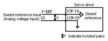

Use when in speed control (analog reference) (Pn041=0, 4, 7, 9, 10)
For general speed control, always wire the VREF and SG terminals. Motor speed is controlled in proportion to the input voltage between V-REF and SG.
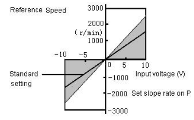
█ Standard Example
Changing “Pn-012” may modify range of speed reference. Pn-012 = 150: This setting means that 10 V is equal to rated speed (1500r/min). Specific example is as follows:
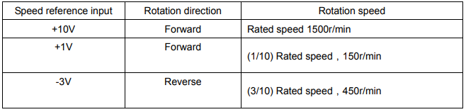
█ Example of input circuit
For noise control, always use multi-twisted cables.
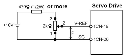
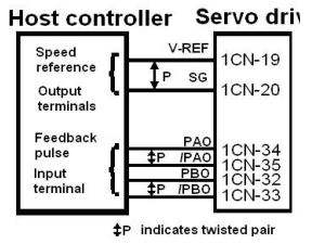
Connect V-REF and SG to speed reference output terminal when host controller is used for position control.
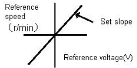
Now please refer to the specification of output voltage to adjust “Pn012”. Adjust the input gain of speed reference by setting the following parameter:

Speed reference is input from V-REF (1CN-19).Set the parameters according to the output of host controller or external circuit. The default setting is adjusted to be allowed by output voltage 10V rated speed.
Note:
- Max allowable voltage is ±10VDC speed reference input end (between 1CN-19 and 20).
Select one of the following four control modes:

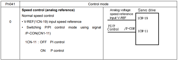
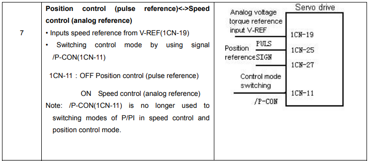
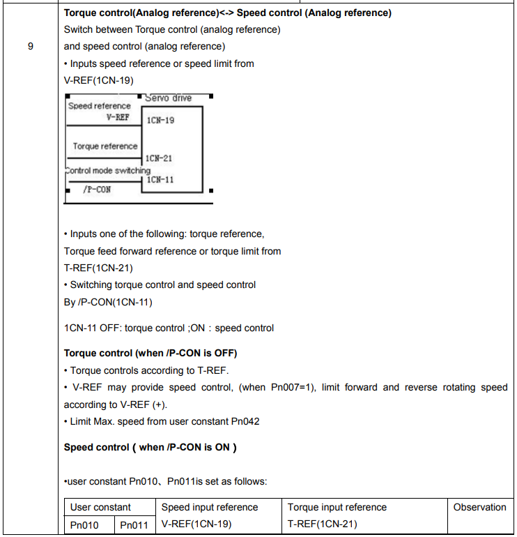
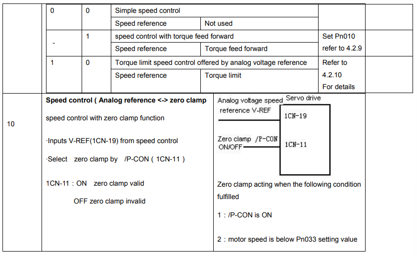
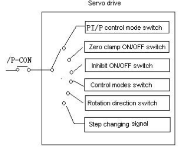
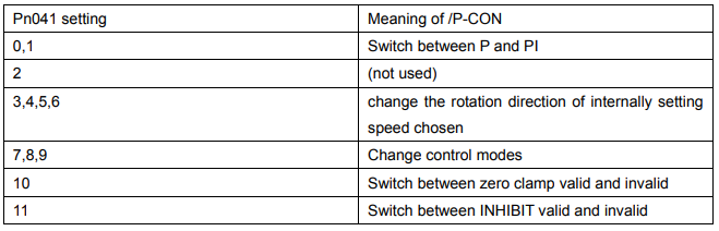
█ / P-CON signal application

Parameter speed reference
Servo motor rotates constantly according to set speed and direction of Pn048 and Pn049 under parameter speed control mode (parameter reference Pn041= 13).
4.2.2 Position reference
Position reference includes: reference pulse input, reference sign input and error counter clear input. There are various applications, please set the best input reference in the system established.
█ Move Reference by Pulse Input Inputs a move reference by pulse input
Position reference can correspond to the following three types of output form:
● Line driver output
● +24V Open collector output
● +12V, +5V Open collector output
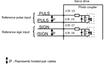
Connection Example 1: Line Driver Output
Line Driver Used:
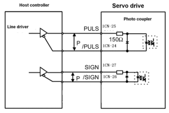
AM26LS31, SN75174 manufactured by Texas Instruments Inc., or MC3487 or equivalent.
Connection Example 2: Host controller is Open-Collector Output with 24VDC power supply
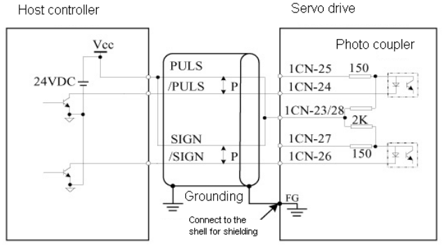
Connection Example 3: Host controller is Open-Collector Output with 12VDC or 5VDC power supply
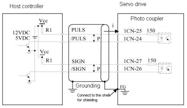
Sets the value of limiting resistor R1 according to following requirement.
Input current I=10~15mA
• When Vcc is 12 V, R1 = 510 kΩ
• When Vcc is 5 V, R1 = 180 Ω
█ Selecting the Reference Pulse Form


The motor only rotates at an angle proportional to the input pulse.
Select “reference pulse status” with the following parameters “Pn008 and Pn009”.
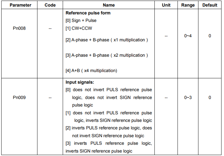
Sets the pulse form according to the host controller specifications
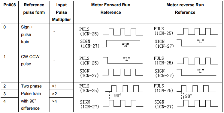
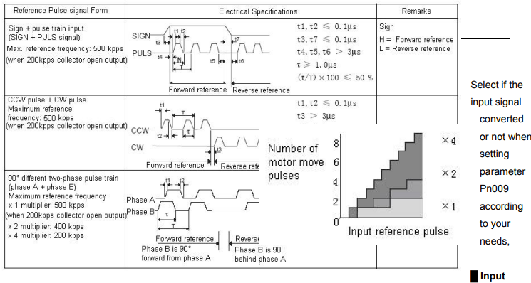
Pulse Multiply Function
When the reference form is two-phase pulse train with 90° phase difference, the input pulse multiply function can be used.
The electronic gear function can also be used to convert input pulses.
Allowable Voltage Level and Timing for Reference Pulse Input
█ Cleaning the Error Counter

Setting the /CLR signal to “L” level does the following:
• Sets the error counter inside the Servo drive to “0”.
• Prohibits position loop control.
In the position control, when servo is OFF, pulse will still remains. Therefore when power is on again (S-ON) pulse signals have to be cleared or clear position move automatically when Servo is OFF by setting user constant Pn005.


█ Position reference one rank filter wave
Position reference one rank filter wave entitle the improvement of pulse reference form designated by the system, thus enhance the stability of position control. But if “position reference position one rack filter time constant (Pn024)” set too high, dynamic function of the system might be decreased

4.2.3 Encoder signal output
Encoder output signals divided inside the Servo drive can be output externally. These signals can be used to form a position control loop in the host controller.
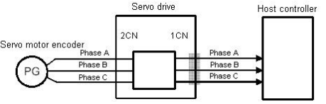
The output circuit is for line driver output. Connect each signal line according to the following circuit diagram.
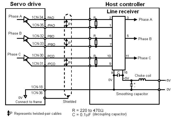
Note: dividing means converting an input pulse train from the encoder mounted on the motor according to the preset pulse density and outputting the converted pulse. The unit is pulses per revolution.
█Output signal
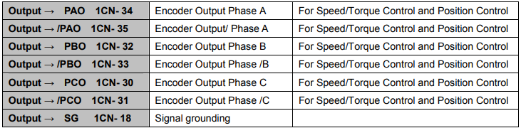
Always connect these signal terminals when a position loop is formed in the host controller to perform position control. Connect SG to host controller 0V.
The output signals forms are shown in the following diagram:
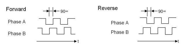
█ Setting the Pulse Dividing Ratio
Set the pulse dividing ratio in the following parameter.

Sets the number of output pulses for PG output signals (PAO, /PAO, PBO and /PBO).
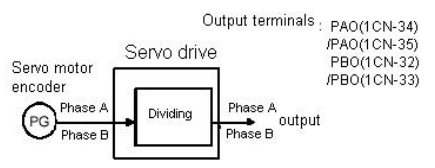
Pulses from motor encoder (PG) are divided by the preset number of pulses before being output. The number of output pulses per revolution is set in this parameter.
Set this value according to the reference unit of the machine or controller to be used. The setting range varies according to the encoder used.
Note
- After changing the parameter setting, always turn the power OFF, then ON.
4.2.4 Contact I/O Signals
Please wiring contact I/O signals that controls servo drive properly.
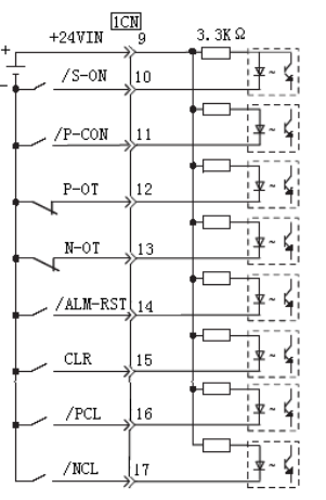
█ Contact Input Signal Terminal Connections Connect these signal terminals as necessary.
Note:
Provide an external I/O power supply separately. There are no power terminals available from the servo drive outputs signals externally.
·External power supply : DC24V±1V,50mA or more It is recommended that this external power supply be the same type as for the output circuit. And the sequence input circuit operation voltage of +24V
ranges from +11V~+25V. +12V power supply could also be applied, but bad contact will occur when the contacts are mechanical and in small current.
Contact Output Signal Terminal Connections

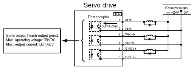
Note :
Provide an external I/O power supply separately. There are no power terminals available from the servo drive outputs signals externally. It is recommended that external power supply be the same type
as for the output circuit.
4.2.5 Position control (parameter reference)
Position control under parameter reference (parameter Pn041= 12). In this mode, servo drive could position with a single axes without host controller.
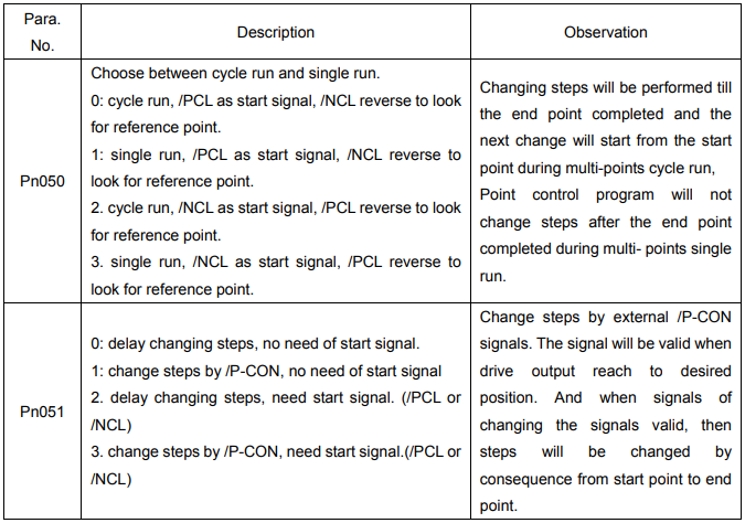
There are 16 position control points with each could set move distance, running speed, constants for acceleration and deceleration and the stop time when positioning completed. Two speeds (1. speed moving towards distance switch “speed of looking for reference point”. 2. Speed moving away from distance switch “moving speed” of reference points could be set as:
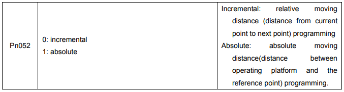
Two position modes: 1. Absolute position mode 2. Relative position mode
Two running modes: 1. Circling mode 2. Non-circling mode
Two step switching method: 1. Delay step switching 2. /P-CON signal switching
Method of looking for reference points: 1. Forward direction 2. Reverse direction
█ Adjusting offset
Offset of each points has two correspondent parameters: one unit of the parameter is 【x 10000 reference pulse】and the other is 【x 1 reference pulse】. Setting range of both parameters is: (-9999----+9999), while offset value equals sum of those two values.
For example:
No.0 offset correspond to parameter Pn059 【x 10000 reference pulse】 and Pn060 【x 1 reference pulse】. Set Pn059 = 100, Pn060=-100.
No.0 offset value = Pn059x10000 reference pulse + Pn060x1 reference pulse
= 100x10000 reference pulse + (-100)x1 reference pulse
= 999900 reference pulse
With the same principle, we can conclude: in order to get the same results, we also can set Pn059 = 99 and Pn060 = 9900.
Thus, we can see when the two parameters are not zero; we can get same result by two ways: one is to set the two parameters both negative or both positive, or one negative the other positive.
It is no doubt that setting the parameter could be realized by communication. In computer, corresponding offset value could be set according to above mentioned method, and one also can set the value directly: choose “independent position running” in the “operation” menu, then set the value without considering sum of two parameter. (Refer to PC communication application software------- SP Windows help documents for detailed steps.)
■ Speed
Speed mention here refers to the steady speed during motor running, which is similar to the pulse frequency given from external in ordinary position control. However, this speed has nothing to do with electronic gear; it is just actual speed of the motor.
■ One rank filter time constant
Same as position reference one rank filter time constant Pn024 during ordinary position control (refer to 4.2.2 for details)
■ Time for change steps after desired position reached
Apply internally delay of changing steps to valid this parameter, that is to set Pn051= 0.

Time for change steps outputs from positioning completed signal CON/, from Servo ON, or from the time when reference point is found till Servo perform the program to control position of the point. Such period of time depends on step changing time required by a point number among start point in program.
For example, the start point of the program Pn219=1, then the step changing time depends on the value of No.0 step changing time Pn187. It could be deduced by analogy when program start points are from 2-15. But when Pn219=0, then the delay time is No.15 point changing steps time Pn202. During this time and time before when Servo is OFF, the step display in monitor is the program start point minus one. If Pn219=0, then the “current point “displays in monitor is “-1”. If Servo OFF after point control program has been performed, then actual step will be displayed in the monitor. Looking for a new reference point, then the “current step” will display the step before program start point.
When running point control program, if error counter is set as “not clear error counter when Servo OFF”, then the error counter might flood. If it does not flood, then the servo drive will probably run at the max. running speed when Servo ON again. PLEASE PAY ATTENTION TO THE SAFETY OF INSTRUMENT.

■ Looking for the reference point
Looking for the reference point is for establishing a zero physical point of the operating platform, which is used as zero point in the coordinates during point position control. And users may choose to find a reference point either in forward side or reverse side.
How to find a reference point
Mount a limit switch in the forward or reverse side, find a reference point in the forward direction after connect to /PCL and in the reverse direction after connect to /NCL. When the operating platform bump into the limit switch, motor will first stop according to the way set by Pn004 and then rotates again against limit switch. When the operating platform completely departed from limit switch and put motor at the position of first photo encoder Phase C pulse. Then position of operating platform is set to be zero point of coordinates.
How to find related parameters of reference point
Speed that towards limit switch is called “speed of looking for reference point “, and the speed moving away from limit switch is called “ moving speed”. These two speeds could be set by following parameters:
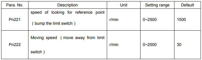
Usually, set speed of looking for reference point (Pn221) high and Moving speed (Pn222) low. Note: if moving speed is too high, precision of finding a reference point would be affected.
Besides, /PCL and /NCL is no longer functioned to limiting external current when looking for a reference point.
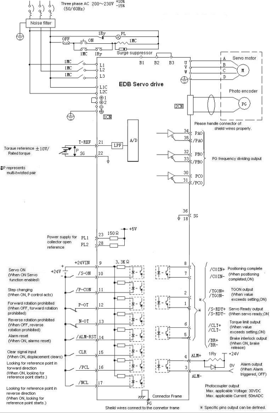
█ Wirings and connections in points control mode
4.2.6 Electronic gear
The electronic gear function enables the motor travel distance per input reference pulse to be set to any value. It allows the host controller to perform control without having to consider the machine gear ratio and the number of encoder pulses.
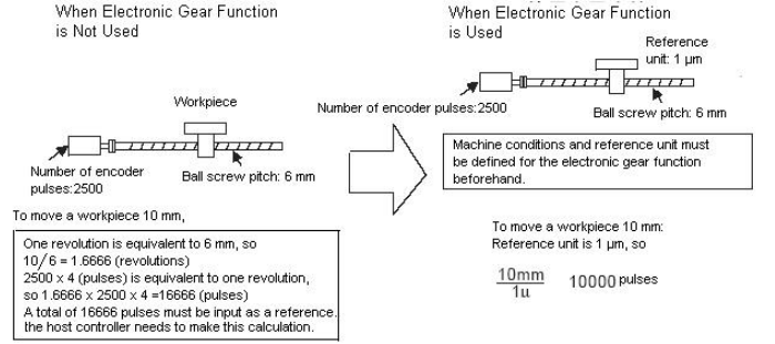
█ Setting the Electronic Gear
Calculate the electronic gear ratio (B/A) according to the procedure below and set the value in Pn022 and Pn023.
1. Check the machine specifications.
Items related to electronic gear:
− Gear ratio
− Ball screw pitch
− Pulley diameter
2. Check the number of encoder pulses for the Servomotor.
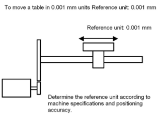
3. Determine the reference unit to be used.
Reference unit is the minimum unit of position data used for moving the load. (Minimum unit of reference from host controller)
Examples:
0.01 mm, 0.001 mm, 0.1°, 0.01 inch
Reference input of one pulse moves the load by one reference unit.
Example: When reference unit is 1 μm
If a reference of 50,000 pulses is input, the load moves 50 mm (50,000 x 1 μm).
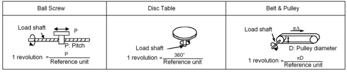
4. Determine the load travel distance per revolution of load shaft in reference units. Load travel distance per revolution of load shaft (in reference units) = Load travel distance per revolution of load shaft (in unit of distance)/ Reference unit
Example: When ball screw pitch is 5 mm and reference unit is 0.001 mm 5/0.001 = 5,000 (reference units)
5. Determine the electronic gear ratio (B/A)
If the load shaft makes “n” revolutions when the motor shaft makes “m” revolutions, the gear ratio of motor shaft and load shaft is m/n

Note: Make sure that the electronic gear ratio meets the following condition: 0.01 ≤ Electronic gear ratio (A/B) ≤ 100
If the electronic gear ratio is outside this range, the Servo drive does not work properly.
In this case, modify the load configuration or reference unit.
6. Set the electronic gear ratio in the parameters below.
Reduce the electronic gear ratio (B/A) to their lowest terms so that both A and B are an integer smaller than 65535, then set A and B in the following parameters.

Set the electronic gear ratio according to machine specifications.
Electronic gear ratio (B
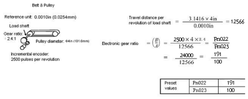
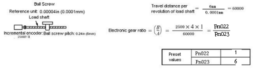
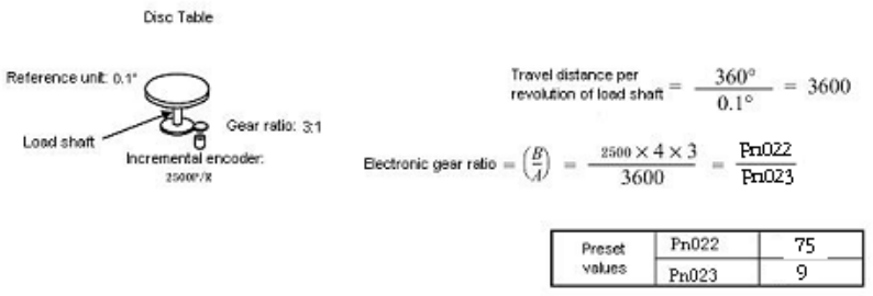
█ Examples of Setting an Electronic Gear Ratio
Examples for Different Load Mechanisms are as follows:
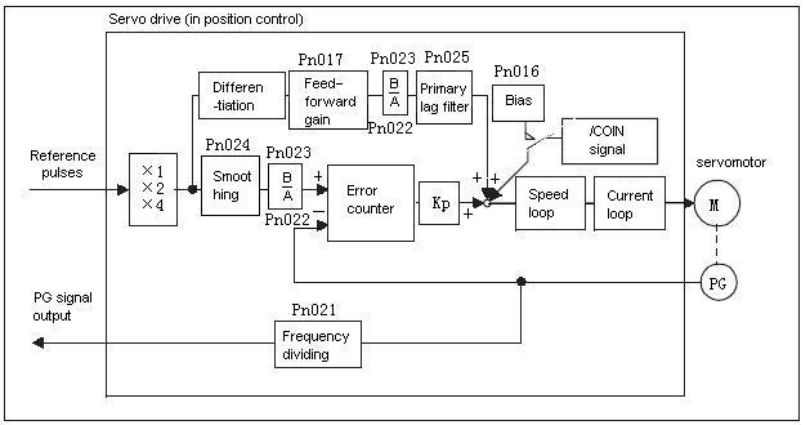
█ Control Block Diagram for Position Control
Note:
In the reference pulse mode, when set the number of actual position pulse, consider if pulse input multiplication function is selected besides electronic gear ratio.
4.2.7 Using Contact Input Speed Control
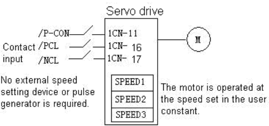
The contact input speed control function provides easy-to-use speed control. It allows the user to initially set three different motor speeds in user constants, select one of the speeds externally by contact input and run the motor.
█ Use the contact input speed control function
To use the contact input speed control function, perform Steps 1 to 3 1. Set Pn41 parameter correctly ,to enable contact input control function

If the contact input speed control function is used, the contents of the input signals shown below will be changed.
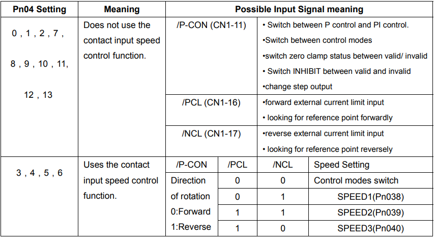
2. Set three motor speeds in the following user constants.
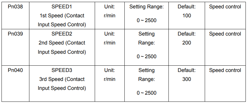
Use these parameters to set motor speeds when the contact input speed control function is used. If a value higher than the maximum speed is set, the maximum speed value is used.
Speed selection input signals /PCL (1CN-16) and /NCL (1CN-17), and rotation direction selection signal /P-CON (1CN-11) enable the motor to run at the preset speeds.
3. Set the soft start time.

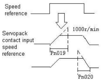
In the Servodrive, a speed reference is multiplied by the preset acceleration or deceleration value to provide speed control.
When a progressive speed reference is input or contact input speed control is used, smooth speed control can be performed. (For normal speed control, set “0” in each parameter.)
Set the following value in each parameter.
█ Pn019: Time interval from the time the motor starts until it reaches 1000r/min.
█ Pn020: Time interval from the time the motor is running at 1000r/min. until it stops
Operating by Contact Input Speed Control Function
Start / Stop
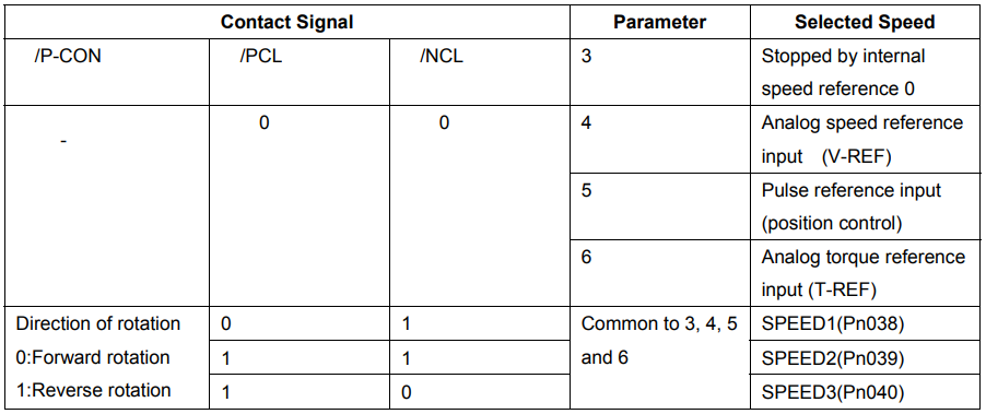
Select the speed by using following input signals:

When Contact Input Speed Control is used and Pn041=3, 4, 5, 6, /PLC, /NLC are specified as internal speed selection. When Pn041=12 under parameter reference position control mode, /PCL and /NCL are specified as switches to look for the reference point. Besides mentioned above, Input signals are used as external torque limit input.
Note:
1) 0: OFF (High level). 1: ON (LOW level)
2) “-” means n
Rotation direction selection
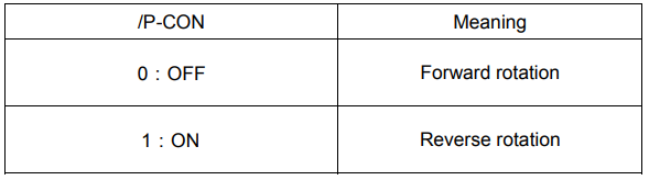
Input signal /P-CON is used to specify the direction of motor rotation.

•When Contact Input Speed Control is used:
Use input signal /P-CON to specify the direction of motor rotation.
•Modes Other Than Contact Input Speed Control:
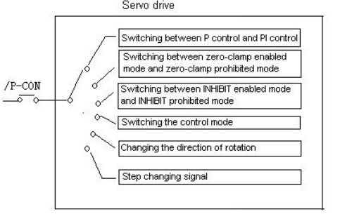
/P-CON signal is used for proportional control, zero-clamp and torque/speed control changeover
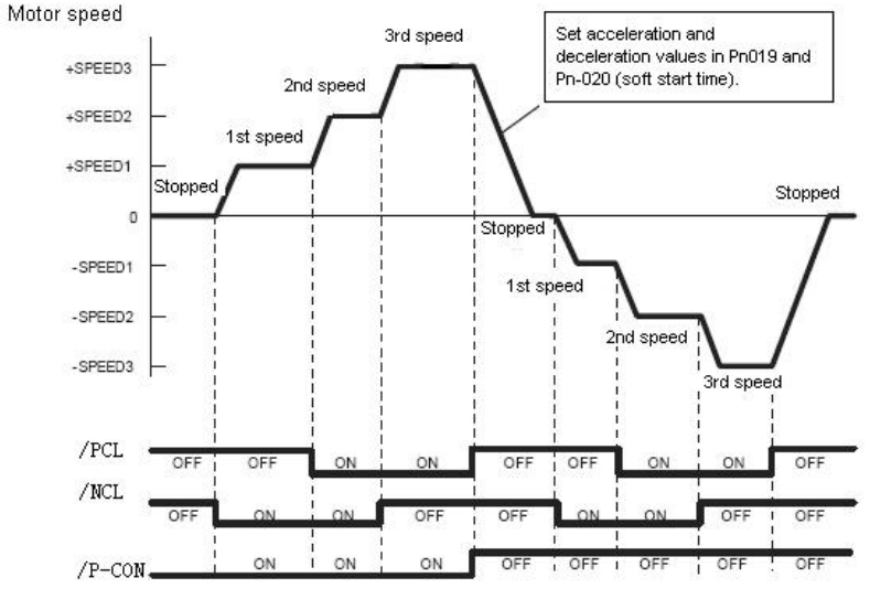
█ Example for contact input speed control operation
The figure below illustrates an example of operation in contact input speed control mode.
Using the soft start function reduces physical shock at speed changeover. Pn041=3.
4.2.8 Using Torque Control
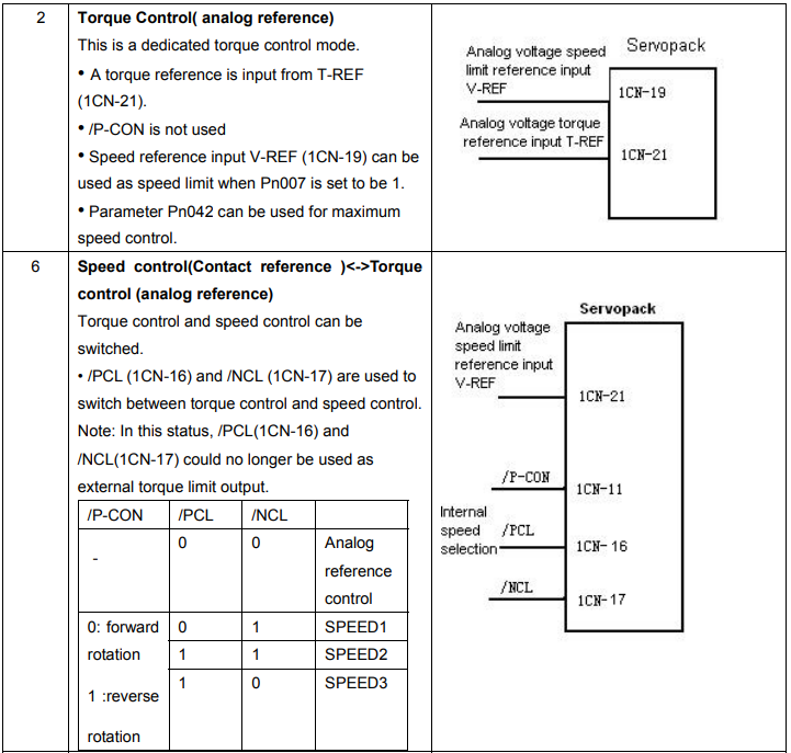
The Servodrive can provide the following torque control:
● Level 1: To restrict the maximum output torque to protect the machine or workpiece (internal Torque restriction) (refer to 4.1.3)
● Level 2: To restrict torque after the motor moves the machine to a specified position (external Torque restriction) (refer to 4.1.3)
● Level 3: To always control output torque, not speed
● Level 4: To switch between torque control and other control
This section describes how to use levels 3 and 4 of the torque control function.
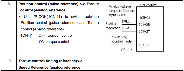
█ Selecting Torque control
Use the following parameter to select level 3 or level 4 torque control.

A motor torque reference value is externally input into the Servodrive to control torque.

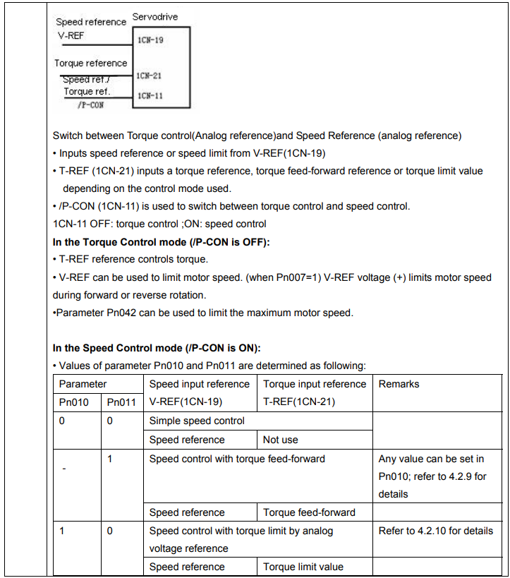
█ Input signal
The following input signals perform torque control.
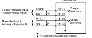
Torque reference input:


These signals are used when torque control is selected.
Motor torque is controlled so that it is proportional to the input voltage between T-REF and SG
Standard setting
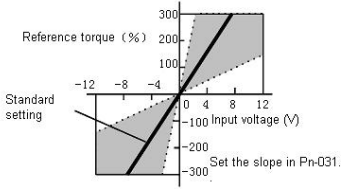

Set the voltage range of torque reference input signal T-REF (1CN-21). Check and set the output status of host controller and external circuit.
For example: Set Pn031=30,
+3 V input → Rated torque in forward direction
+9 V input → 300% of rated torque in forward direction
−0.3 V input → 10% of rated torque in reverse direction
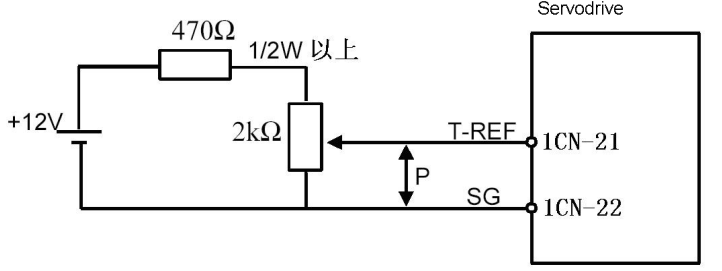
Example of Input Circuit: (See the figure below)
Speed limit input:

Standard setting:
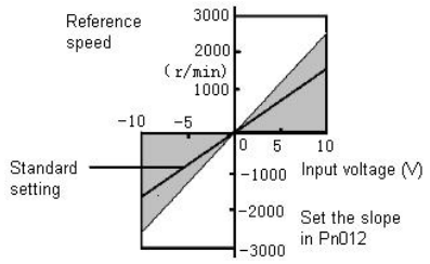
For example: Set Pn012=250, then
+6 V input → 1500 r/min in forward direction
+1 V input → 250 r/min in forward direction
−3 V input → 750 r/min in reverse direction
Parameter Pn012 can be used to change the voltage input range. (This is also applicable to speed restriction.)
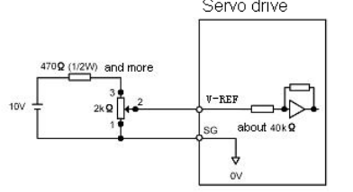
Example of Input Circuit (see the following figure):
• For noise control, always use twisted pair cables.

Internal speed limit
Set Pn007=0, there’s no external analog speed limit with only internal speed limit available. Set Pn042 it sets internal limit value of motor speed in torque control mode.

External speed limit
Set Pn007=1 to use external speed limit
Use Speed reference V-REF analog as external speed limit output. Usually, value of V-REF should be smaller than Pn042 max. speed limit to entitle the external speed limit meaningful.

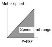
According to status of host controller and external circuit, use Pn012 to set speed reference input gain and determine external limit value. Principle of
Speed Restriction:
When the speed exceeds the speed limit, negative feedback of torque
proportional to the difference between the current speed and the limit speed is performed to return the speed to within the normal speed range. Therefore, the actual motor speed limit value has a certain range depending on the load conditions.
4.2.9 Using Torque Feed-forward Function
For speed control (analog reference) only.
The torque feed-forward function reduces positioning time. It differentiates a speed reference at the host controller to generate a torque feed-forward reference, and then sends this torque feed-forward reference and the speed reference to the SERVODRIVE.
Too high a torque feed-forward value will result in overshoot or undershoot. To prevent this, set the optimum value while observing system response.
Connect a speed reference signal line and torque feed-forward reference signal line from the host controller to V-REF (1CN-19,20) and T-REF (1CN-21,22) respectively.
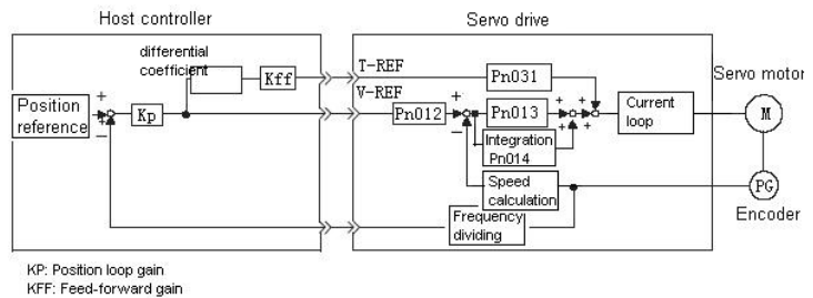
█ How to Use Torque Feed-forward Function
To use the torque feed-forward function, set the following memory switch to 1.

This function cannot be used with the function for torque restriction by analog voltage reference.
To use the torque feed-forward function, input a speed reference to the V-REF terminal and a torque feed-forward reference to the T-REF terminal.
The host controller must generate a torque feed-forward reference.
█ Setting:
The value of torque feed-forward value is determined by Pn031 (set according to Host controller)
The factory setting is Pn031 = 30. If, for example, the torque feed-forward value is ±3 V, torque is restricted to ±100% (rated torque).

4.2.10 Using Torque Restriction by Analog Voltage Reference
For speed control (analog reference Pn041=9) only.
This function restricts torque by assigning the T-REF terminal (1CN-21, 1CN-22) a torque limit value in terms of analog voltage. Since torque reference input terminal T-REF is used as an input terminal, this function cannot be used for torque control. When /PCL signal (1CN-16) is ON, the forward torque is under restriction. When /NCL (1CN-17) is ON, the reverse torque is restricted.
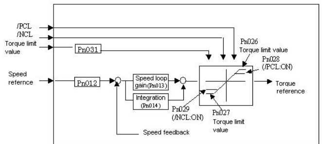
█ How to Use Torque Restriction by Analog Voltage Reference
To use this torque restriction function, set the following memory switch to 1 to enable analog voltage reference as external torque limit.

Besides, set Pn011=0, torque feed-forward function is disenabled.

To use this function, input a speed reference to the V-REF terminal and a torque limit value to the T-REF terminal. According to /PCL and /NCL status, set forward and reverse rotation torque limit respectively.
Refer to the following table for details,
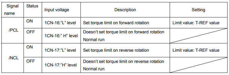
█ Setting
Set torque reference gain in parameter Pn031

4.2.11 Using the Reference Pulse Inhibit Function (INHIBIT)
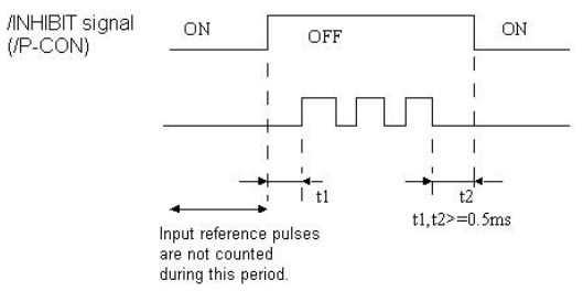
This function causes the Servo drive to stop counting input reference pulses in position control mode. While this function is being used, the motor remains in servo locked (clamped) status.
The /P-CON signal is used to enable or prohibit this function.
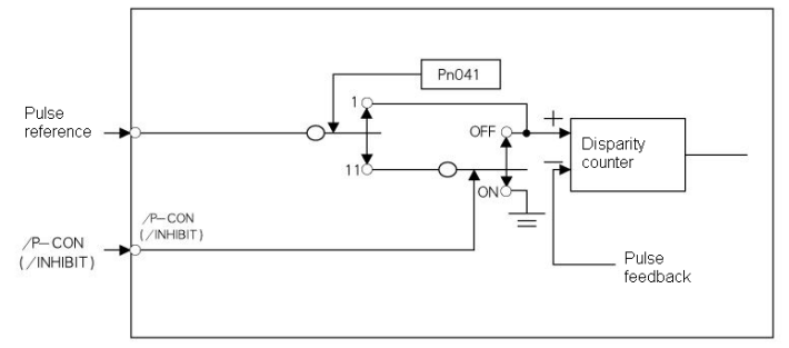
█ How to Use Reference Pulse Inhibit Function: INHIBIT
To use the INHIBIT function, set parameters as follows.

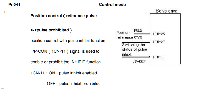
█ Relationship between INHIBIT Signal and Reference Pulse
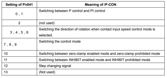
█ How to use /P-CON signal
4.3 Setting up the parameter
4.3.1 Setting the Jog Speed
Use the following parameter to set or modify a motor speed

If a value higher than the maximum speed is set, the maximum speed value is used. This parameter is used to set a motor speed when the motor is operated using a Digital Operator. Refer to 5.2.3 for details.
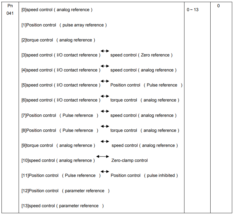
4.3.2 Selecting the control modes
Select different control modes by setting following parameters.

█ Control mode introduction
Control modes mentioned above are described as follows:
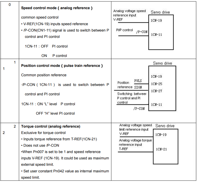
[0]speed control (analog reference)
Speed control mode used for analog voltage reference input. Please refer to 4.2.1 Speed reference
[1]position control(pulse array reference)
Position control mode for pulse array input reference. Please refer to 4.2.2 Position reference
[2]Torque control (analog reference )
Torque control mode for analog voltage input reference. Please refer to 4.4.8 Torque control
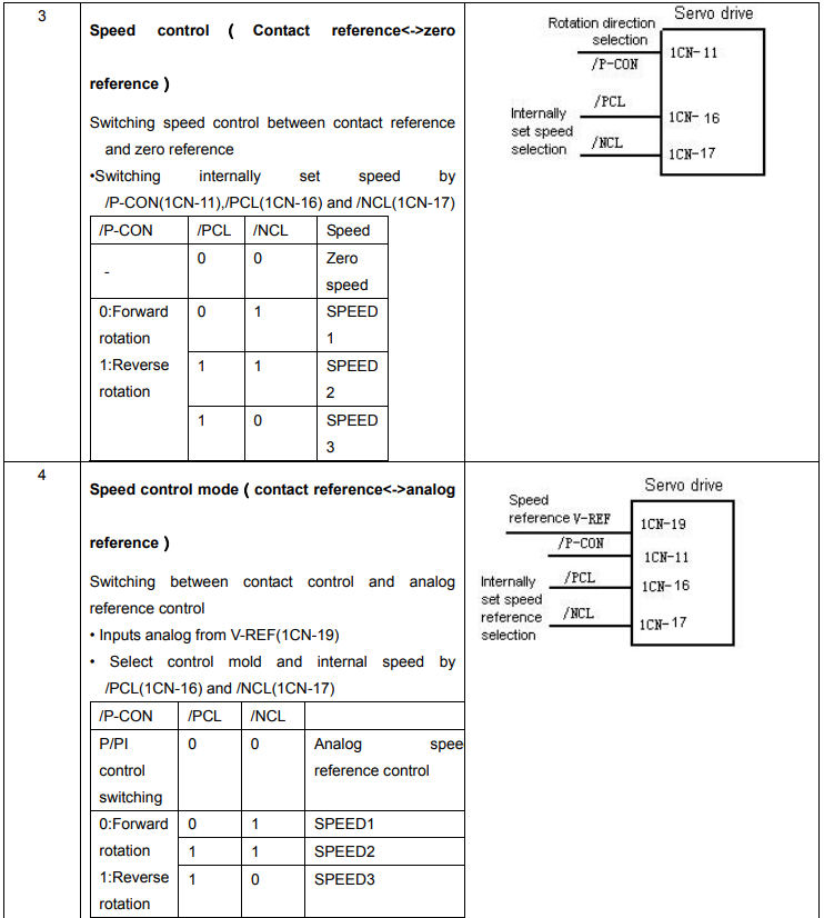
[3]speed control (I/O contact reference ) speed control (zero reference)
Control mode for internally set speed selection and zero reference. Please refer to 4.2.7“Internally set speed selection”
[4]speed control (I/O contact reference ) speed control (analog reference )
Mode that could switch contact reference speed control and analog voltage reference speed control. When signal /PCL and /NCL are OFF(H level), the analog reference speed control is enabled. Please refer to 4.2.7” internally set speed selection”.
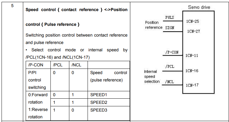
[5]speed control (I/O contact reference ) position control(pulse instruction)
Mode that could switch between contact reference speed control and pulse train reference position control. When signal /PCL and /NCL are OFF(H level), pulse train reference position control is enabled. Please refer to 4.2.7” Internally set speed selection”
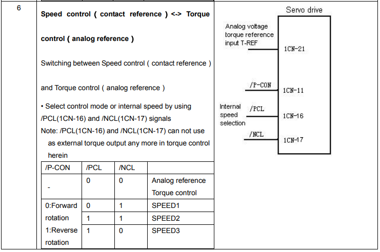
[6]speed control (I/O contact reference ) torque control (analog reference )
Mode that could switch between contact reference speed control and analog voltage input torque control. When /PCL and /NCL signals are OFF(H level), Analog voltage reference torque control is enabled. Please refer to 4.2.7 ” Internally set speed selection”
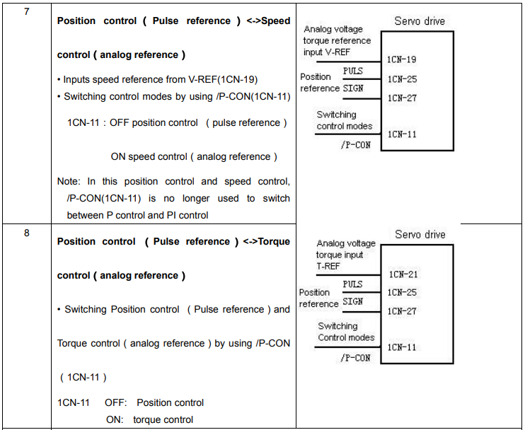
[7]position control(pulse reference) speed control (analog reference )
Mode that could switch between position control and speed control by /P-CON signal
[8]position control(Pulse reference) torque control (analog reference )
Mode that could switch between position control and torque control by /P-CON signal
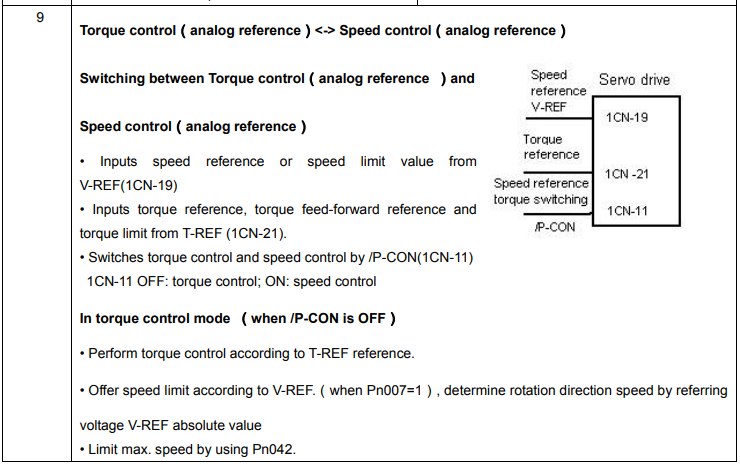
[9]torque control (analog reference ) speed control (analog reference )
Mode that could switch between torque control and speed control by /P-CON signal Please refer to 4.2.8 Torque control
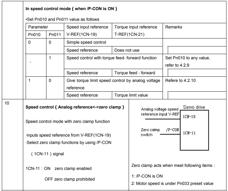
[10]speed control (analog reference ) zero-clamp control
Speed control mode that allow zero clamp function setting when servo drive stops. Zero clamp acts after P-CON signal is ”ON”(L level). Please refer to 4.4.3” zero clamp”.
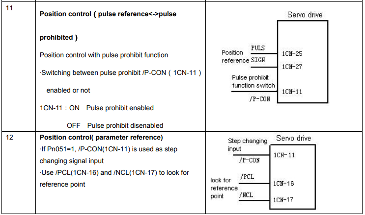
[11]position control(pulse reference) position control(pulse prohibit)
Position control mode that use /P-CON signal to stop reference pulse stop (prohibit). Please refer to 4.2.11” reference pulse inhibits function”
[12]position control(parameter reference )
Servodrive could perform position control without host controller. Please refer to 4.2.5 contact control
[13]speed control (parameter reference )
Servodrive performs according to the speed and rotation direction set by Pn048 and Pn049, please refer to 4.2.1.
Meanings of some parameters under various control modes are as follows


4.4 Setting Stop Mode
4.4.1 Adjusting Offset
█ Why Does not the Motor Stop?”
When 0 V is specified as reference voltage for speed/torque control (analog reference), the motor may rotate at a very slow speed and fail to stop. This happens when reference voltage from the host controller or external circuit has a slight offset (equal to reference offset) (in mV units). If this offset is adjusted to 0 V, the motor will stop.
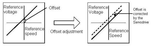
█ Adjusting the Reference Offset
The following two methods can be used to adjust the reference offset to 0 V

Please refer to 5.2.4 “automatic adjustment of speed reference offset” and 5.2.5 “manual adjustment of speed reference offset” for detailed procedures.
Note: If a position control loop is formed in the host controller, do not use automatic adjustment and always use manual adjustment.
4.4.2 Using Dynamic Brake
To stop the servomotor by applying dynamic brake (DB), set desired values in the following memory switch. If dynamic brake is not used, the servomotor will stop naturally due to machine friction.
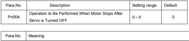
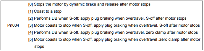
The Servodrive enters servo OFF status when:
• Servo ON input signal (/S-ON, 1CN-10) is turned OFF
• Servo alarm arises
• Power is turned OFF
Note:
Dynamic brake is a performance that forces motor to stop. Don’t use Power ON/OFF or Servo ON signal (/S-ON) to stop and restart servo motor frequently. Otherwise service life of internal elements of servo drive will be shortened.
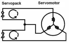
Dynamic brake (DB)
One of the general methods to cause a motor sudden stop.
“Dynamic brake” suddenly stops a servomotor by shorting its
electrical circuit.
This dynamic brake circuit is incorporated in the servodrive.
4.4.3 Using Zero-Clamp
The zero-clamp function is used for a system in which the host controller does not form a position loop by speed reference input. In other words, this function is used to cause the motor to stop and enter a servo locked status when the input voltage of speed reference V-REF is not 0 V. When the zero-clamp function is turned ON, an internal position loop is temporarily formed, causing the motor to be clamped within one pulse. Even if the motor is forcibly rotated by external force, it returns to the zero-clamp position.
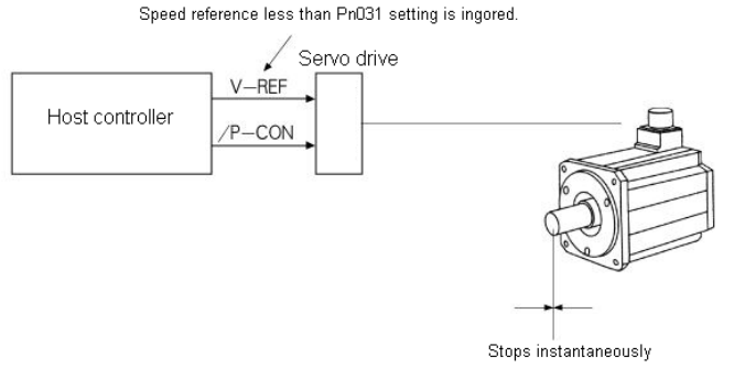
█ Setting
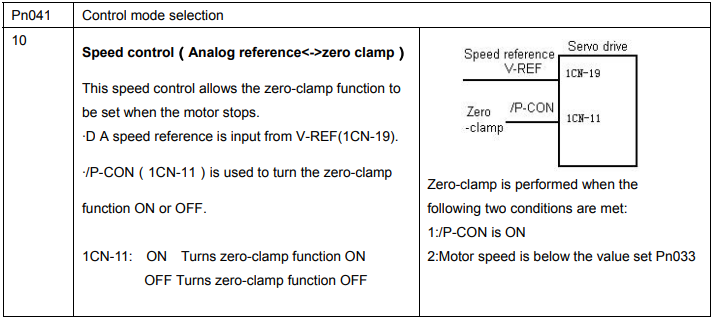
Set the Pn041 to 10 and select speed control(analog reference)—zero clamp control so that input signal /P-CON can be used to enable or disable the zero-clamp function.

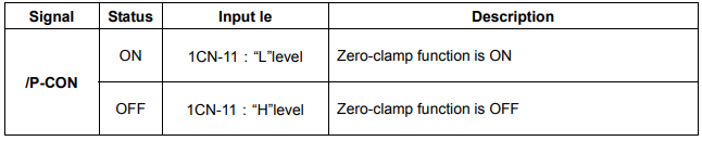
The following table shows zero clamp status when /P-CON is turned ON and OFF.

If zero-clamp speed control is selected, set the motor speed level at which zero-clamp is to be performed. If a value higher than the maximum motor speed is set, the maximum speed value is used.
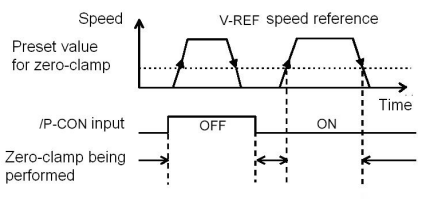
Conditions for Zero-clamp
Zero-clamp is performed when all the following conditions are met:
• Zero-clamp speed control is selected (Parameter Pn041=10).
• /P-CON (1CN-11) is turned ON (0 V).
• Motor speed drops below the preset value.
4.4.4 Using Holding Brake
Holding brake is useful when a servo drive is used to control a vertical axis. A servomotor with brake prevents the movable part from dropping due to gravitation when the system power is turned OFF.
Servodrive brake interlock outputs (/BK) signals to control if the holding brake function is turned on or not in a servomotor with brake.
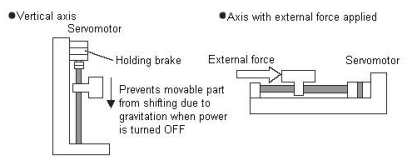
Before connection please make sure the servo motor is detached with the machine and confirm the performance of servomotor and holding brake action. If both works normal, then connect the servomotor and machine and test.
█ Connecting example
Use Servodrive contact output-signal /BK and brake power supply to form a brake ON/OFF circuit. An example of standard wiring is shown below.
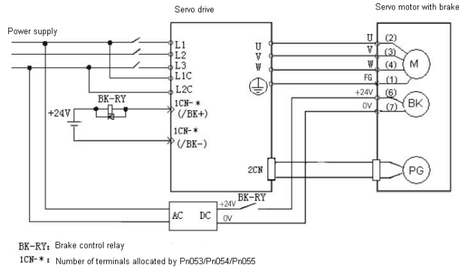

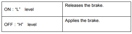
This output signal controls the brake when a motor with brake is used. This signal terminal need not be connected when a motor without brake is used.
Set the following parameter to specify the 1CN pin to which the BK signal is output.

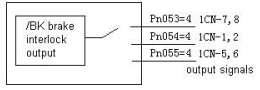
Pn053, Pn054 and Pn055 signal functions are shown as follows:


Related parameters:
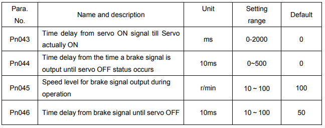
█ Brake ON and OFF Timing
If the machine moves slightly due to gravity when the brake is applied, set the following parameter to adjust brake ON timing:

This parameter is used to set output timing of brake control signal /BK and servo OFF operation (motor output stop) when servomotor with brake is used.
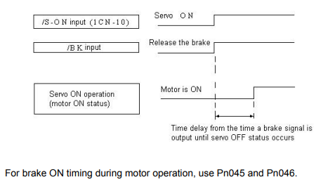
Note:
When alarm triggers, motor will instantly turn OFF. Due to gravity and other reasons, machine might move until brake stops.
█ Setting
Set the following parameters to adjust brake ON timing so that holding brake is applied when the motor stops.

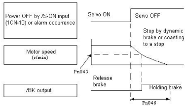
Pn045 and Pn046 are used for servomotors with brake. Use these parameters to set brake timing used when the servo is turned OFF by input signal /S-ON\ or alarm occurrence during motor rotation.
Brakes for servomotors are designed as holding brakes. Therefore, brake ON timing when the motor stops must be appropriate. And after this period of time, motor rotating speed will no longer affect the brake performance. Adjust the parameter settings while observing machine operation.
Conditions for /BK signal output during motor operation: (The circuit is opened in either of the following situations.)
1. Motor speed drops below the value set in Pn045 after servo OFF occurs.
2. The time set in Pn046 has elapsed since servo OFF occurred.
If a value higher than the maximum speed is set, the maximum speed value is used.