
5. Using the digital operator
5.1 Basic operator
5.1.1 Digital Operator Functions
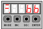
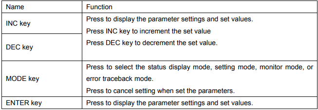
The Digital Operator allows the user to set parameters, send commands, and display operating status. This section describes the key names and functions of the Digital Operator in the initial display status.
5.1.2 Resetting Servo Alarms
Press ENTER key to reset servo alarm in state monitor mode The alarm state could also be cleared by using 1CN-14(/ALM-RST) input signal. The alarm state can be cleared by turning the main power supply OFF, then turning the control power supply OFF.
Note:
After an alarm occurs, remove the cause of the alarm before resetting it
5.1.3 Basic Functions and Mode Selection
Digital Operator operation allows status display, parameter setting, operating reference, and auto-tuning operations.
Basic Mode Selection
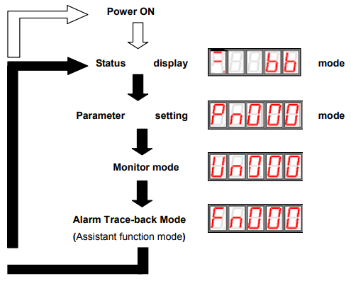
The four basic modes are listed below. Each time the mode key is pressed, the next mode in the sequence is selected.
5.1.4 Operation in Status Display Mode
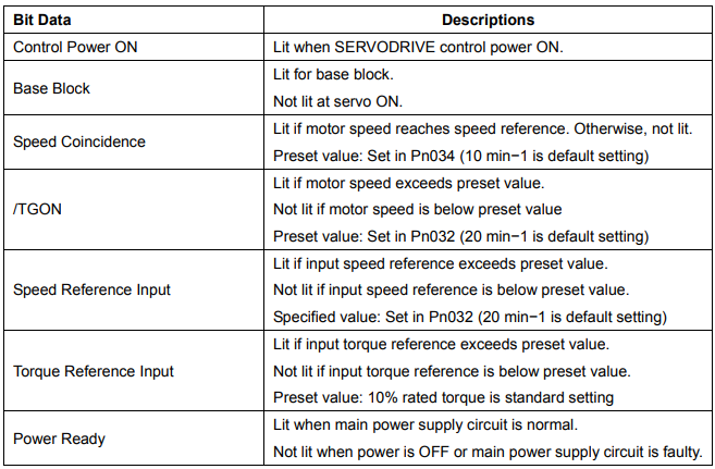
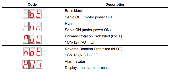
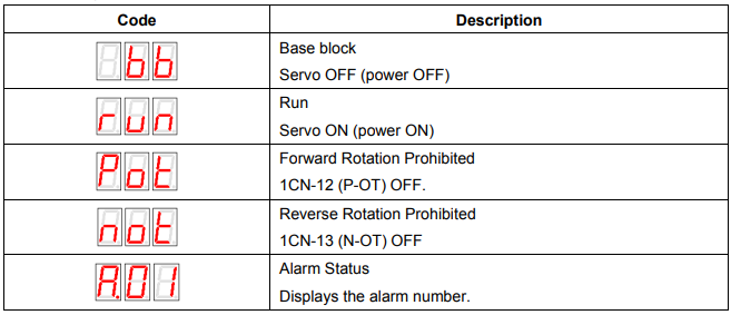
The status display mode displays the Servodrive status as bit data and codes.
█ Selecting Status Display Mode
The status display mode is displayed when the power is turned ON. If the status display mode is not displayed, select the mode by using Mode Key to switch.
█ Keys to the status display are shown below.
The display varies in different modes.
For Speed and torque Control
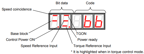
Bit displays
Code displays
For position control
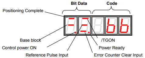
Bit data displays
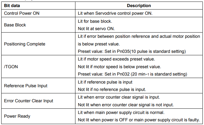
Code displays
5.1.5 Operation in Parameter Setting Mode
Select or adjust the functions by setting parameters. The parameter list is in the appendix.
█ Parameter changing procedures are described below:
The constant settings allow setting of a constant. Check the permitted range of the constant in Appendix List of Parameters, before changing the data. The example below shows how to change user setting Pn012 100 to 85.
1. Press MODE to select parameter setting mode.

2. Press INC key or DEC key to select parameter number.

3. Press ENTER key to display parameter data in step 2.

4. Press INC or DEC to change the data to the desired number 00085. Hold the button to accelerate the change of value. When the data reaches the max. or Min., the value will remain unchanged, if press INC/DEC.
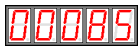
5. Press ENTER to store the value.
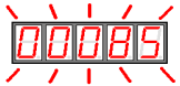
6. Press ENTER again to go back to parameter display.

5.1.6 Operation in Monitor Mode
The monitor mode allows the reference values input into the SERVODRIVE, I/O signal status, and Servodrive internal status to be monitored.
The monitor mode can be set during motor operation.
█ Using the Monitor Mode
The example below shows how to display 1500, the contents of monitor number Un-001.
1. Press MODE to select monitor mode.

2. Press INC key or DEC key to select the monitor number to display.

3. Press ENTER to display the data for the monitor number selected at step 2.
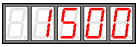
4. Press ENTER once more to display the monitor number.

5. Above is the procedure for display 1500 in monitor number Un001
█ Monitor Mode Displays
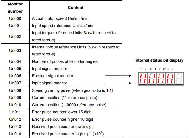
Note: 1. the current setting is (Un010*10000+Un009) reference pulse
2. When Un011 between -9999 and 9999, Un011 displays as algorism. Otherwise, it deplays as hex.
3. Received pulse number displays as algorism(Un014x104 +Un013). When it reaches 99999999, it shall not be able to increse anymore.
Bit data
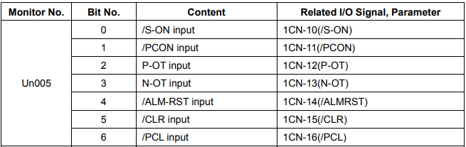

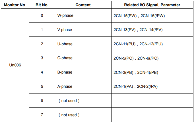
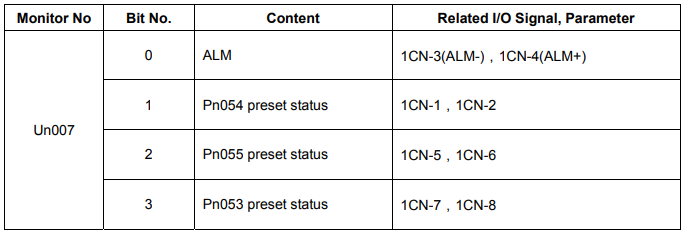
Operation Using the Digital Operator
If it is in the assistant function mode, some operations could be select in digital operator. The detailed functions are shown as below:
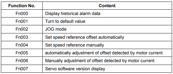
5.2.1 Alarm Trace-back Data
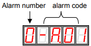
In alarm trace-back data, latest ten times alarms could be displayed.
The following shows the procedure to display the historical record.
1. Press MODE to select assistant function mode
2. Press INC or DEC to select function number of alarm historical record.

3. Press ENTER to display the latest alarm code.
4. Press INC or DEC to display other recent occurred alarm code.
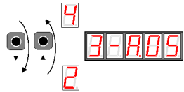
5. Press ENTER to return to function number display.

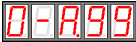
If the user wants to clear all the record, just hold ENTER for one second, then all the historical data will be deleted.
5.2.2 Operation of recovering to default value
The follows are procedures to recovery of default value.
1. Press MODE to select assistant mode.
2. Press INC or DEC to select function number of recovering to default value

3. Press ENTER to enter parameter default recovery mode.

4. Hold ENTER key for one second to recover the parameter to default setting.

5. Release ENTER key to return to function number display.

5.2.3 Operation in JOG mode
The following is steps in JOG mode
1. Press MODE to select assistant mode.
2. Press INC or DEC to select Function number of JOG mode.

3. Press ENTER to enter JOG mode.

4. Press MODE to enter Servo ON (motor ON) status.

5. Press MODE to switch between servo ON and Servo OFF. If motor running is required, servo must be ON.
6. Press INC or DEC (motor runs when press the keys.)
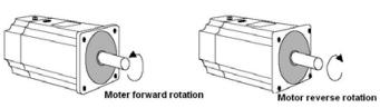
7. Press ENTER to return to function number display.(Servo is OFF)

5.2.4 Reference Offset Automatic Adjustment
The motor may rotate slowly when the reference voltage is intended to be 0 V. This occurs when the host controller or external circuit has a small offset (measured in mV) in the reference voltage.
The reference offset automatic adjustment mode automatically measures the offset and adjusts the reference voltage.
It adjusts both speed and torque references. The following diagram illustrates automatic adjustment of an offset in the reference voltage from the host controller or external circuit.
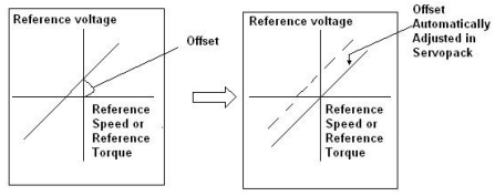
After completion of offset automatic adjustment, the amount of offset is stored in the Servodrive.
The amount of offset can be checked in the speed reference offset manual adjustment mode. Refer to Reference
Offset Manual Adjustment Mode for details
The reference offset automatic adjustment mode cannot be used where a position loop is formed with the host controller and the error pulses are zeroed when servo lock is stopped.
In this case, use the speed reference offset manual adjustment mode. Refer to Reference Offset Manual
Adjustment Mode for details.
Zero-clamp speed control is available to force the motor to stop during zero speed reference. Refer to Using Zero-Clamp for details.
Follow the procedure below to automatically adjust the reference offset:
1. Input the (intended) 0 V reference voltage from the host controller or external circuit.
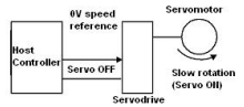
2. Press Mode to select assistant function mode.
3. Press INC or DEC key to select function number of speed reference offset.

4. Press ENTER to enter mode that automatically adjust the reference offset.
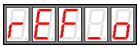
5. Press MODE. When the flashing lasts for one minute, the speed offset is adjusted automatically.
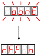
6. Press ENTER to return to function number display

7. This is the end of reference offset automatic adjustment.
5.2.5 Reference Offset Manual Adjustment Mode
Speed reference offset manual adjustment is very convenient in the following situations:
• If a loop is formed with the host controller and the error is zeroed when servo lock is stopped.
• To deliberately set the offset to some value.
Offset Adjustment Range and Setting Units are as follows:
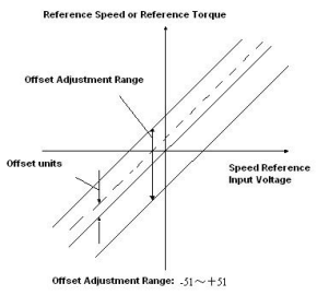
The following is procedures of adjusting reference offset manually.
1. Press MODE to select assistant function mode.
2. Press INC or DEC to select reference offset manual adjustment function number
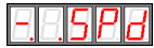
3. Select ON signal(/S-ON)ON, it displays as follows
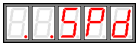
4. Press ENTER key for a second to display speed reference offset

5. Press INC or DEC to adjust the offset.
6. Press ENTER for a second to display the interface on step 4.
7. Press ENTER again to go back to function display.

This ends the procedure.
5.2.6 Motor Current Detection Offset Adjustment
Current detection offset adjustment is performed at Anaheim Automation before shipping. Basically, the customer need not perform this adjustment. Perform this adjustment only if highly accurate adjustment is required when the Digital Operator is combined with a specific motor.
This section will describe the operation of automatic offset and manual offset.
Note:
Current detection offset manual adjustment could only be performed when the Servo is OFF.
Any accidentally activation of this function especially the manual adjustment, deteriorated situations might occur.
If the torque pulse is obviously too high compared with other Servodrives. Please adjust the offset automatically.
■ motor current detection offset automatic adjustment
Follow the procedure below to perform current detection offset automatic adjustment
1. Press MODE key to select assistant function mode.
2. Press INC key or DEC key to select function number of motor current detection offset automatic adjustment.

3. Press ENTER to enter motor current detection offset automatic adjustment.
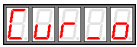
4. Press MODE key and the adjustment will be finished after it flashes for a second.
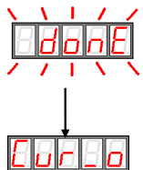
5. Press ENTER to return function number display.
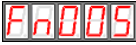
This ends the operation of adjusting the motor current detection offset automatic adjustment
■ motor current detection offset manual adjustment
Follow the procedure below to perform current detection offset manual adjustment
1. Press MODE key and select assistant function mode.
2. Press INC key or DEC key to select function number of motor current detection offset manual adjustment.
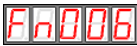
3. Press ENTER key to enter into motor current detection offset manual adjustment.

4. Press MODE key to switch U phase(Cu1_o)and V phase(Cu2_o)current detection offset adjustment mode.

5. Hold ENTER key for a second, current phase current detection data will be displayed.

6. Press INC key or DEC key to adjust the offset.

7. Hold ENTER key for a second to return the display of step 3 or step 4.
8. Press ENTER again to go back to function number display.

This ends the operation of the motor current detection offset manual adjustment
Note:
motor current detection offset manual adjustment range:-102~+102。
5.2.7 Checking Software Version
Use the following procedure to check the software version.
1. Press MODE key and select assistant function mode.
2. Press INC key or DEC to select the function number for servo software version.

3. Press ENTER to display software version(D is displayed at the highest position)
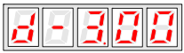
4. Press Mode key to display FPGA/CPLD software version(P is displayed at the highest position)
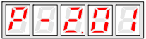
5. Repress Mode key and switch back to display the DSP software version
6. Press ENTER key to return to display the function number