
6. Communication functions
6.1 RS-485、RS-232、RS-422 Communication hardware interface
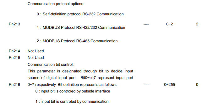
EDB-A Servo drives have RS-485、RS-232、RS-422communication functions. With the help of these functions, it can achieve reference modification and monitor servo drive status etc., However, RS-485,RS-232and RS-422 can not be applied at the same time. It’s selective for RS-485/RS-232/RS-422 through the options of parameter Pn213. The instruction as follows:
RS-232
It’s a must to use Anaheim Automation special RS232 cable of BST-CC24.
Instructions:
The cable length is less than 15 meters when in a less disturbed environment. However, if transmission speed is above 38.4Kbps, it’s strongly recommended that the cable length is less than 3 meters to ensure the accuracy of transmission.
RS-485、RS422
Communication cable wring diagram:
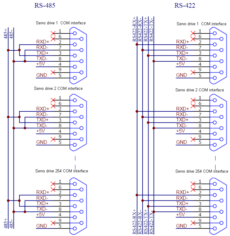
Instructions:
1. The cable length is less than 100 meters when in a less disturbed environment. However, if transmission speed is above 38.4Kbps, it’s strongly recommended that the cable length is less than 15 meters to ensure the accuracy of transmission.
2. It’s available for up to 32 PCS servo drives to work togeter when RS422 or RS485 is applied. In case more servo drives control needed, relay stations are required.
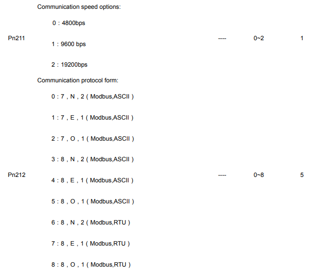
6.2 RS-485、RS-232、RS-422 communication parameter

Note:
1. After change the communication address through communication (that is to say, after change the value of Parameter Pn210), the servo drive will still response data with previous communication address. It takes 40ms for the servo drive to change into new communication adress.
2. After change the communication speed through communication (that is to say, after change the value of Parameter Pn211), the servo drive will still response data with previous communication speed. It takes 40ms for the servo drive to change into new communication adress.
3. After change the communication protocol through communication (that is to say, after change the value of Parameter Pn212), the servo drive will still response data with previous communication protocol. It takes 40ms for the servo drive to change into new communication adress.
4. If change the communication parameter (Pn210~Pn212) through key boards of the panel, turn off the power before turn on it again to enable the change effective.
6.3 MODBUS communication protocol
Only when Pn213 is set as 1 or 2 can communication be put into operation with MODBUS protocol. There are two modes for MODBUS communication. They are ASCII(American Standard Code for information interchange)mode or RTU(Remote Terminal Unit)mode.
The brief introduction as follows:
6.3.1 Code meaning
ASCII mode:
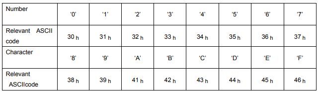
Every 8-bit datum is consisted by two ASCII characters. For instance: One 1-byte datum 64 h(Hex expression)is expressed as ASCII code ‘64’. It contains ‘6’as ASCII code(36 h) and‘4’as ASCII code(34 h).
ASCII code for Number 0 to 9、character A to F are as follows:
RTU mode:
Every 8-bit datum is consisted by two 4-bit hex datum. That is to say, a normal hex number. For instance: algorism 100 can be expressed into 1-byteRTU datum as 64 h.
Datum structure:
10bit character form(apply in 7-bit datum)
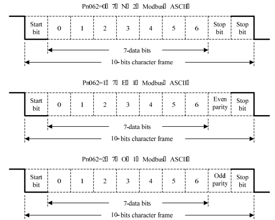
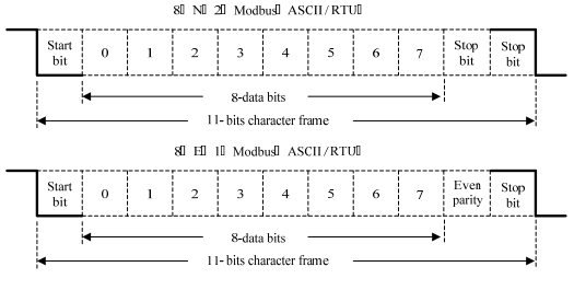
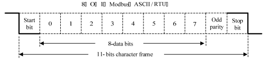
11bit character form(apply in 8-bit datum)
Communication protocol structure:
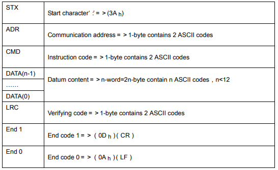
Communication protocol datum structure:
ASCII mode:
RTU Mode:
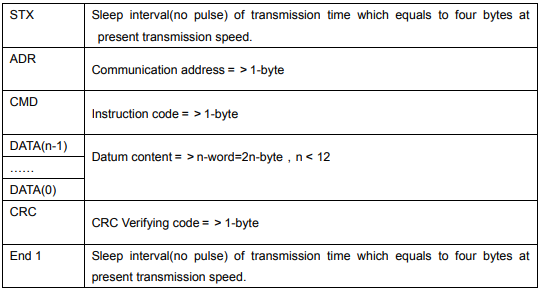
Communication protocol datum structure instruction as follows:
STX(communication start)
ASCII mode:‘:’ character.
RTU mode: Sleep interval(no pulse) of transmission time which equals to four bytes at present transmission speed.
ADR(communication address)
Acceptable communication addresses range from 1 to 254.
For instance, to communicate with servo address as 32(hex as 20):
ASCII mode:ADR=‘2’,‘0’=>‘2’=32 h,‘0’=30 h
RTU mode:ADR=20 h
CMD(order instruction) and DATA(datum)
Datum structure is formed by order code. Regular order code as follows:
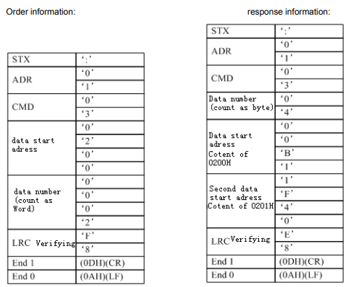
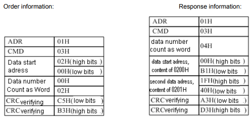
Order code: 03 h, read N words,N is not more than 20.
For instance: read 2 words from address 0200 h from servo addressed at 01 h.
ASCII mode:
RTU mode:
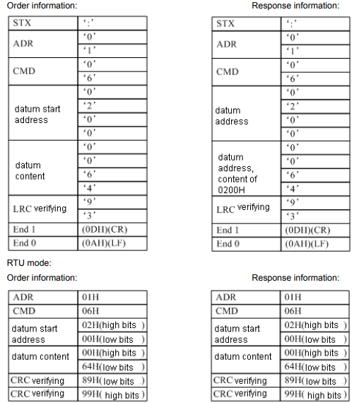
Order code: 06 h,write in one character(word)
For instance: write 100 (0064 h)in address 0200 h of servo addressed 01 h.
ASCII mode :
6.3.2 Communication fault disposal
While communication, faults may occur. Normal faults as follows:
- While read/write parameter, datum address is wrong;
- While write in parameter, the datum exceeds the maximum value of this parameter or is less than the minimum value of this parameter;
- Communication is disturbed, datum transmission fault or verifying code fault;
When above mentioned communication faults occur, servo drive running won’t be affected. Meanwhile, servo drive will feed back a faulty frame.
The faulty frame form as follows:
Host controller datum frame

Servo drive feedback fault frame:

Thereinto:
Fault frame response code=order+80 h;
Fault code=00 h:communication in gear;
=01 h:servo drive cannot identify the required functions;
=02 h:the required address do not exist in the servo drive;
=03 h:the required datum in the servo is not workable. (beyond maximum or minimum value of the parameter);
=04 h:servo drive starts to execute the requirement, but cannot achieve it;
For instance: servo drive addressed at03 h,write in06 h into parameter Pn002, however, because both the maximum
and minimum value of parameter Pn002 are zero, therefore the datum will not be adapted, servo drive will return a fault frame. The fault code is 03. Frame is as follows:
Host controller datum frame:

Servo drive feedback fault frame:

Besides, if the datum from host controller indicated servo drives address as 00 h , it represents this datum is broadcasting datum, servo dries will not return any frames.
6.3.3 Servo state data communication address
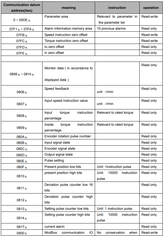
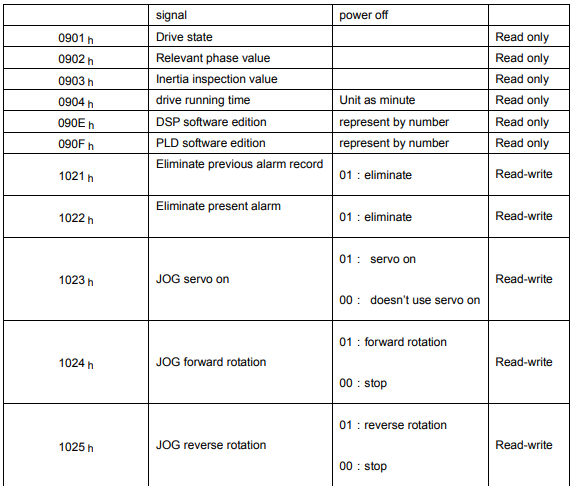
Please refer to the following list for all of communication parameter address of this servo:
Instruction:
1、parameter area(communication address 0000 h ~ 00DE h)
is relevant to parameters in the parameter list. For instance: parameter Pn000 is relevant to communication address 0000 h; parameter Pn101 is relevant to communication address 0065 h; read-write operation to address 0000 h is the read-write operation to Pn000. if the input datum is out of the parameter range, the datum shall be abnegated and servo drive will return an operation unsuccessful signal. If the parameter is modified successfully, the parameter shall be memorized when power off.
2、alarm information storage area(07F1 h ~ 07FA h)
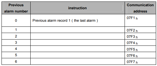

3、monitor data area(0806 h ~ 0814 h)
These monitor data are relevant to servo drive display panel Un000~Un014.
For instance: read address 0807 h (speed setting) through communication as FB16 h. therefore, the speed setting is-1258RPM.
4、ModBus communication IO signal
Use communication to control input number IO signal. This datum won’t be reserved after power off.
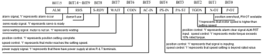
5、drive state(0901 h)
This 1-word represents the current state of the system. Meaning of each bit as follows:
6、software edition(090E h)
It represents drive’s software edition by number. E.g. if the number is 0D300 h,it means the software edition is d-3.00.