
7. Advanced Functions
7.1 Multi-type Area Monitoring
Function Overview
By setting up safety zones, the position of the robot can be monitored in real time under a variety of working conditions, minimizing the likelihood of collisions.
WorkArea:
All CheckPoints (TCPs) of the robot are only allowed to move within the WorkArea. In the event of a violation of the WorkArea rules, there are two ways of handling:
− When the robot leaves the WorkArea, the program stops and alarms
− The robot runs properly if in the WorkArea and outputs a signal if the output port is configured to Enable
BlockedArea:
All CheckPoints (TCPs) of the robot are not allowed to move within the BlockedArea. In the event of a violation of the BlockedArea rule, there are two ways of handling:
− When the robot enters a Blocked Area, the program stops and alarms
− The robot runs properly if not in a Blocked Area, and outputs a signal if the output port is configured to Enable
SignalArea:
All CheckPoints (TCPs) of the robot are only allowed to move within any areas. In the event of a violation of the WorkArea rules, there are two ways of handling:
− When the robot enters the signal work area, it continues to run the program and outputs a signal if the output port enable is configured
− When the robot leaves the signal work area, it continues to run the program and outputs a signal if the output port enable is configured
How to use standard area monitoring
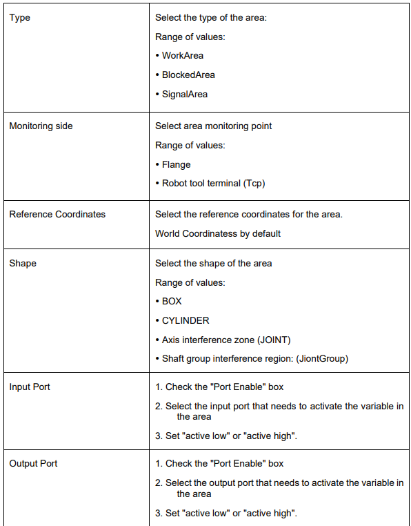
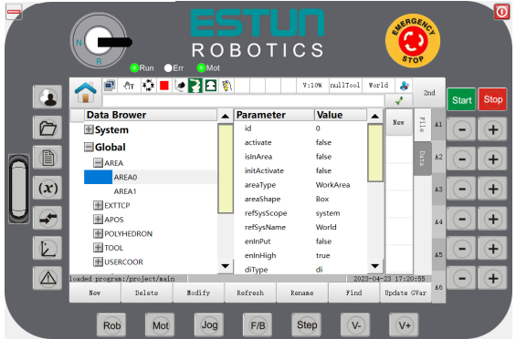
Step 1 Go to the program data interface and click on the standard area variable you want to set in the global domain, e.g. AREA0. Click on " Modify " and you will be taken to the interface for setting the area variable.
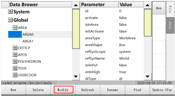
Step 2 By default, the standard area variable is "inactive" and the user can activate it by clicking "Activate".
Step 3 Click on "Modify" as shown in Figure 7-1.
Figure 7-1 Interface fdor setting standard area variables ---Box/Cylinder
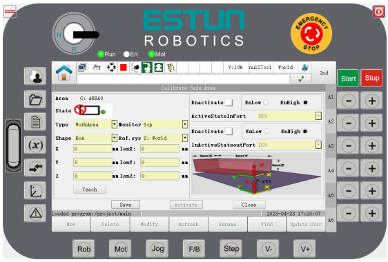
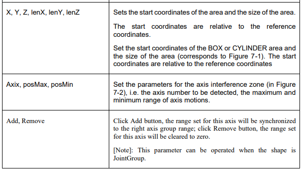
Figure 7-2 Interface for setting standard area variables - Axis interference zone
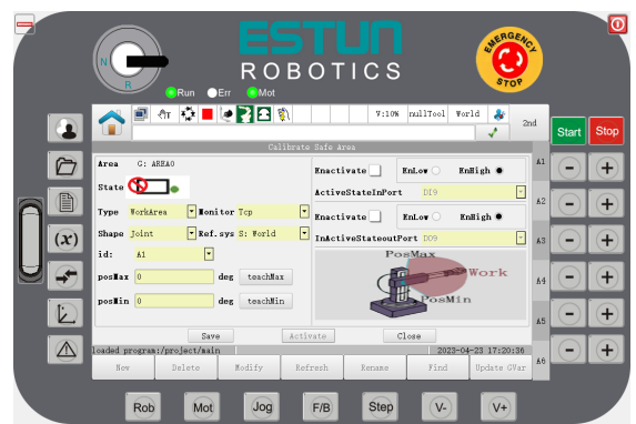
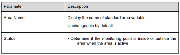
Step 4 Modify the parameters of this interface as described below.

Step 5 Click "OK" to complete the setting of the standard area variables, as shown in Figure 7-3.
Figure 7-3 Interface for standard area variables
Note
1. When the standard area activates or deactivate the function, the activation or deactivation can be performed via the variable configuration interface, the command or the input port (the input port number enabled by the configuration).
2. When the standard area input port is enabled, the area can be activated or deactivated (co-existing with the standard area activation command and the standard area deactivation command, whichever is triggered later) by entering the edge of the port number.
3. When a standard area is activated, the default is to set this standard area property to be activated automatically.
4. Auto-activation Attribute: When the system reboots and loads a standard area, the standard area attribute is auto-activated and the input port enable is not set, the area is automatically activated; when the standard area attribute is auto-activated and the input port enable is set, the area is activated or not according to the level status of the set input port number.
5. When the standard area is active, the status of whether the robot is in the setup area is output in real time; after the output port is enabled and set, a signal can be output according to the status of whether the robot monitoring end is in the setup area.
6. When the standard area is activated and the area type is a WorkArea or BlockedArea, the robot periodically detects the position of the monitoring end of the robot. If it is outside the WorkArea or inside the BlockedArea, a corresponding alarm will be generated during the robot's movement.
7. For the additional axes configured as welding jaws, the welding jaws participate in the detection when they are in the coupled state; the welding jaws do not participate in the detection when they are in the decoupled state.
8. If an axis is set in the area of both JointGroup and Joint type, the monitoring takes effect at the same time.
Method for using Polyhedron area monitoring
When using the "Polyhedron Area" monitoring function, the polyhedron area needs to be configured first.
Step 1: Click on "User Application > Polyhedron Area" to enter the Polyhedron Area plugin interface, as shown in Figure 7-4. Currently, up to 4 polyhedron regions are supported.
Figure 7-4 Polyhedron Area plugin interface
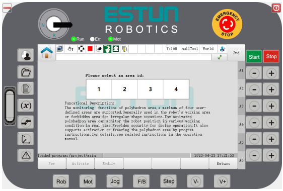
Step 2: Select the ID of the area to be configured and enter the configuration interface.
1. If the configuration interface is entered after clicking on the area ID, as shown in Figure 7-5, it means that the area has already been configured with a polyhedral area. Please refer to Step 3 to modify the parameters.
Figure 7-5 Polyhedron area variable configuration interface
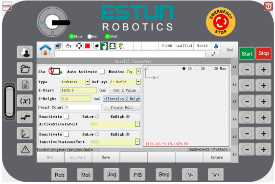
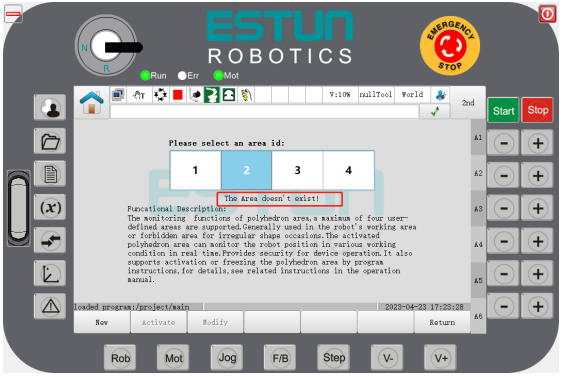
2. If, after clicking on the area ID, it appears as shown in Figure 7-6, please click on the "Create" button, enter the configuration interface, and then click on the "Modify" button to modify the parameters by referring to Step 3.
Figure 7-6 Configuration interface for polyhedron area variables
Step 2: Modify the parameters of the configuration interface according to the following instructions:
Status: After activation of this area, determine whether the monitoring point is inside or outside the area.
Auto Activation: When selected, this area will be automatically activated after the controller starts.
Monitoring Point: Select the monitoring point of the area, which currently includes the robot flange and Tcp.
Type: Select the type of this area.
Coordinate System: Select the reference coordinates for this area, which defaults to the World Coordinates.
Vertex Z Value: Indicate the starting position of the area in the Z-direction of the coordinates. It can be entered manually or obtained by clicking the "Get Current Z Value" button, which displays the current Z-axis coordinate value in the current coordinates.
Area Height: Indicate the height of the area in the Z-direction of the coordinates. It can be entered manually or calculated by clicking the "Calculate Z-Height" button, which displays the Z-axis coordinate value of the current coordinates minus the vertex height value.
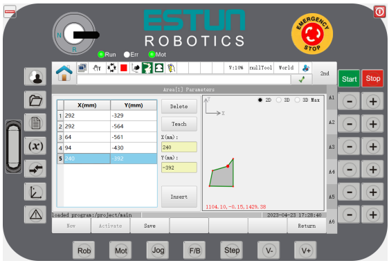
Count of Vertices: Indicate the count of vertices on the bottom of the polyhedron area. Clicking on "Vertex Information" will bring up the vertex configuration interface, as shown in Figure 7-2. Clicking on "Add" will automatically add the current TCP position in the user coordinates. If you need to modify a vertex of the polyhedron area, select the corresponding vertex and modify it by clicking on "Teach" or entering the XY coordinates. If you need to delete a vertex of the polyhedron area, select the corresponding vertex and click on "Delete". The right side of the interface supports the preview of the 2D and 3D effects of the polyhedron area, as well as the enlarged 3D effect of only the polyhedron area. Preview supports synchronous display of the monitoring point position (blue dot in the figure). In 2D mode, only the position of the monitoring point in the XY plane is displayed, and switching to 3D mode can preview the relative position of the actual monitoring point;
Input Port: Check "Port Enable" to select the input port that needs to activate this area variable, and set it to "Low Active" or "High Active".
Output Port: Check "Port Enable" to select the output port that needs to activate this area variable, and set it to "Low Active" or "High Active".
Figure 7-7: Configuration interface for polyhedronal area vertex
Step 1: Click "Save" after completing the settings.
Step 2: When using a polyhedron area in the command, create a POLYHEDRON type variable and specify the correct polyhedron area ID in the "index" parameter. After creation, activate or deactivate the polyhedron area using the PolyhedronAreaActivate or PolyhedronAreaDeactivate command.
Note
1. When the polyhedron area is activated and the area type is a WorkArea or a BlockedArea, the
system will periodically check the robot monitoring point position during operation and output the
robot's status in the set area in real time.
2. When the standard area is activated and the area type is a signal area, the system will periodically
check the robot monitoring point position regardless of whether the excitation is on or off and output
the robot's status in the set area in real time.
3. After setting the automatic activation parameter for the polyhedron area, it will not take effect
immediately. The system will load the polyhedron parameters during a restart and determine whether
to activate the area automatically based on the DI port status. When the DI port is disabled, the area
is automatically activated, and when the DI port is enabled, the area is activated or not depending on
the DI level.
4. The logic for activating or deactivating the polyhedron area is the same as the usage status of the
input/output port and standard area monitoring function.
5. The activation or deactivating of the polyhedron area can be performed through the variable
configuration interface, instructions, or input ports (if configured).
----END
7.2 Collision Detection
7.2.1 Collision Detection
Function Overview
The collision detection function can detect whether the robot collides in real-time without the need for an external force sensor. If a collision is detected, the robot will immediately alarm and stop working, providing safety protection and effectively reducing the damage to the robot or other equipment. Users can turn ON or OFF the collision detection function according to the needs of the site. For safety reasons, it is recommended to turn on the collision detection function.
Way of use
If the current robot model does not support collision detection, the interface will display "The current robot model does not support collision detection".
This function detects collisions based on load information and device information, so the load information must be set correctly to avoid false alarms or affect detection sensitivity. For setting the load parameters, please refer to "PAYLOAD0" (6.5) and "SetPayload" commands (6.5).
.Different working conditions and operating conditions may result in different collision sensitivities with the same parameter settings. Therefore, false alarms may occur. If a collision false alarm occurs, appropriately reduce the sensitivity of the collision axis according to the alarm information by increasing the numerical value until the false alarm no longer occurs.
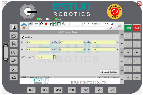
Step 1: Select "General Settings>Collision Detection" on the System Home to enter the setting interface as shown in Figure 7-8.
Figure 7-8 Collision detection configuration interface
Parameter Introduction:
Enable Checkbox: Controls the on/off switch of the Collision Detection feature.
Checked: Enable the Collision Detection.
Unchecked: Disable the Collision Detection.
Values for Axis 1-6: Set the sensitivity of the Collision Detection.
Default value: 100
Larger value: Lower sensitivity for the Collision Detection.
Smaller value: Higher sensitivity for the Collision Detection.
Collision IO: The system outputs to the DO port when the collision backoff is done. <N/A> indicates no output, while other values output a high level to the corresponding DO port.
7.2.2 Collision Detection Self-Adjustment
Function Description
This function generates matching Collision Detection parameters based on the actual operating status of the robot, which can improve the sensitivity of the collision detection and reduce the probability of false alarms.
The target path's running data is recorded through the function setting, and the collision detection selfadjustment parameters are calculated based on the recorded data. The obtained self-adjustment parameters are then used.
Way of use:
This function requires the Collision Detection feature to be enabled and ensures that the target path for the Collision Detection Self-adjustment can operate properly.
Step 1: Select "General Settings> Collision Detection> Advanced Settings" on the System Home to enter the setting interface.
Step 2: Check the "Enable" checkbox in the upper left corner, as shown in Figure 7-8.
Step 3: Click the "Advanced Settings" button in the lower right corner to enter the "Collision Detection SelfAdjustment" page.
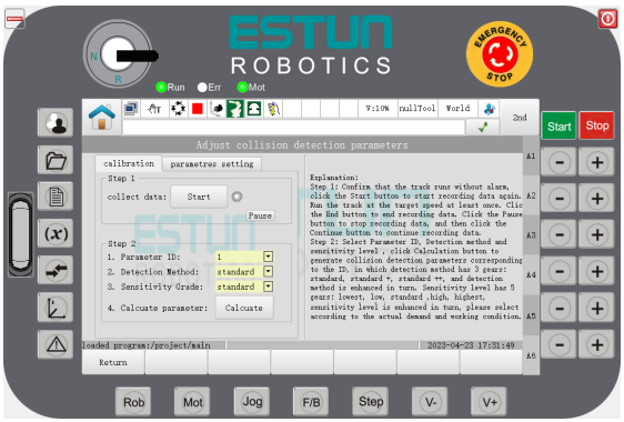
Step 4: Select the "Calibration" tab, click the "Start" button to re-record the self-adjustment data, run the robot's target path, and interrupt data collection by clicking the "Pause" button. Data collection can be resumed by clicking the "Resume" button. Run the target path at least once at the target speed, then click the "End" button to end data collection.
Step 5: Select the "Parameter ID", "Detection Method", and "Sensitivity Level" based on actual needs, and click "Calculate".
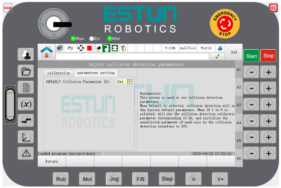
Step 6: Select the "Collision Detection Parameter Settings" tab to set the default parameters for the Collision Detection.
Parameter Introduction
Calibration Tab:
Start/End: Re-record the self-adjustment data/End data collection.
Pause/Resume: Interrupt data collection/Resume data collection.
Parameter ID: 1-6, used to store the calculated collision detection self-adjustment parameters.
Detection Method: Standard, Standard+, Standard++, corresponding to the detection methods in order of increasing strength.
Sensitivity Level: 5 levels: Lowest, Low, Standard, High, Highest, corresponding to sensitivity levels in ascending order.
Calculate: Calculate the Collision Detection self-adjustment parameters based on the set parameters.
Parameter settings of collision detection
Default Collision Detection Parameter ID: The factory default parameter is "DEFAULT," and 1-6 corresponds to the self-adjustment parameters in "Parameter ID" 1-6.
7.3 Collision Rollback
When a robot collides with an object, it will immediately stop moving but maintain contact with the object.
This creates contact stress between the robot and the object, potentially leading to damage. The Collision Rollback function allows the robot to move back along its original path for a certain distance after the collision, in order to release the stress.
When a collision occurs, the robot triggers an alarm and quickly stops its movement. It then moves back along its original path to prevent contact with the obstacle and release the stress.
The first stage of the process is a quick stop of the robot's movement when it detects a collision.
The second stage involves moving back along the original path from the collision stop point to the end point of the rollback.
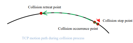
Figure 7-9 TCP motion path during collision
Note
To use this function, you need to contact the manufacturer.
7.4 Vibration Suppression
Function Overview
The Vibration Suppression function is used to reduce residual vibration at the end of the robot, allowing for smoother motion, to improve positioning accuracy, and shorter positioning time. The strength of the residual vibration varies depending on the robot's movement path, as well as its speed and end load.
Typically, high-speed movement and heavy end loads are more likely to cause vibration and produce stronger vibrations.
Way of use
Note
When using the Vibration Suppression function, it is essential to set the correct payload parameters, which affect the controller's adjustment of vibration suppression.
Refer to the Basic Setting Interface for Setting Payload Parameters (4.7.2) and the SetPayload Command (6.5) for information on setting payload parameters.
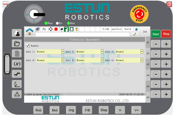
Step 1: Enter the configuration interface for vibration suppression by selecting "General Settings>Vibration Suppression" on the System Home, as shown in Figure 7-10.
Figure 7-10: Vibration Suppression Configuration Interface
Parameter Description
Enable Checkbox: The switch controlling the Vibration Suppression function ON/OFF.
Checked: Enable the Vibration Suppression function.
Unchecked: Disable the Vibration Suppression function.
Values for Axis 1 to Axis 6: Set the strength of vibration suppression.
Default Value: Standard.
Value Range: There are five levels: Low, Low-Medium, Standard, Medium-High, and High. The vibration suppression effect increases progressively with each level.
7.5 Conveyor tracking
Function overview
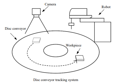
The conveyor tracking is designed to synchronize the movement of the robot and the workpieces on a conveyor, which move along the conveyor as it runs. The position information of the workpiece is obtained through a visual system or sensor, and transmitted to the robot via a designated interaction method. This allows the robot to pick up the workpiece from a fixed or moving conveyor based on the feedback from the sensor. There are two types of conveyors available, namely linear and disc-shaped.
Figure 7-11 Schematic diagram of the linear conveyor tracking system
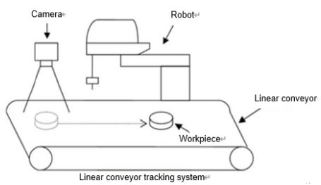
Figure 7-12 Schematic diagram of the disc conveyor tracking system

To access the conveyor configuration interface, users can click on "User Application-Conveyor Tracking" in the programming pendant. In this interface, conveyor parameters can be configured, including enabling the conveyor belt, checking and calibrating the pulse equivalent, viewing the conveyor belt position and speed, and toggling the display of reasons for non-tracking. Users can also switch between five configuration pages, namely "Conveyor Belt Parameters," "Tracking Parameters," "Trigger Parameters," "Visual Parameters," and "Virtual Conveyor Belt," to further configure the settings.
Way of use
Note
Up to two conveyors are supported.
Step 1: Select "User Application-Conveyor Tracking" on the System Home, which will take users to the conveyor configuration interface.
Figure 7-13 Configuration interface for linear conveyor parameters
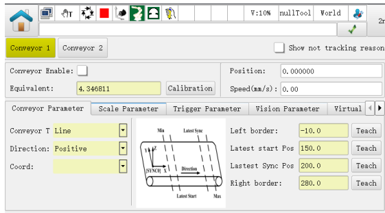
Parameter Description
Display cause of tracking failure:
Checked: Display the causes for tracking failure.
Unchecked: Do not display the causes for tracking failure.
Conveyor Enable: The switch controlling the Conveyor Tracking
Checked: Turn on the Conveyor Tracking function.
Unchecked: Turn off the Conveyor Tracking function.
Pulse equivalent:
Conveyor position:
Conveyor speed:
Conveyor Parameter Configuration
Select "Conveyor Parameter" to enter the conveyor parameter tab.
Type: Linear or Disk.
Figure 7-14 Configuration interface for linear conveyor parameters
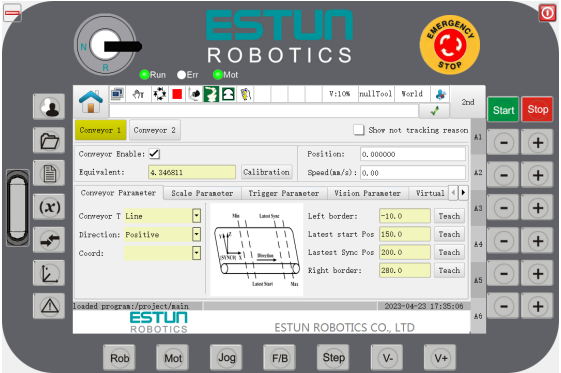
Figure 7-15 Configuration interface for disc conveyor parameters
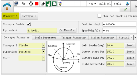
Direction: set the direction of the conveyor belt.
Moving coordinate system: The moving coordinate system bound to such conveyor.
Min./max. boundary/latest start point/latest synchronization point: For a linear conveyor, these represent the coordinate values in the X-direction in the corresponding moving coordinates. For a disc conveyor, they represent the angle at the center of the XOY plane in the corresponding moving coordinates.
Tracking Parameters Configuration
Select "Tracking Parameters" to enter the conveyor parameters configuration interface.
Figure 7-16 Configuration interface for tracking parameters
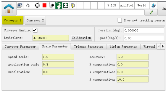
Velocity coefficient/Accel coefficient/Decel coefficient: the ratios of the velocity/Accel/Decel during the tracking synchronization process.
Tracking tolerance: the threshold used to judge the accuracy of the tracking synchronization, representing the maximum allowable displacement error between the robot and the target object.
X-axis compensation: the compensation for workpiece offset relative to the target position in the X direction.
Y-axis compensation: the compensation for workpiece offset relative to the target position in the Y direction.
A-axis compensation: the compensation for workpiece offset relative to the target position in the A direction.
Trigger Parameter Configuration
Select "Trigger Parameters" to enter the trigger parameter configuration interface.
Figure 7-17 Configuration iInterface for trigger parameter
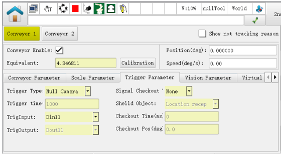
Trigger Types:
− Timing trigger: The system will output a high level signal from the trigger output port based on the configured trigger time (ms) and cycle, of which high-level hold time is 1/2 of the trigger time.
− External IO trigger: When the system detects a rising edge signal at the trigger input port (detection cycle of 4ms), set the trigger output port to output a high level signal. The high-level hold time is synchronized with the trigger input port.
− Non-camera trigger: No visual operation mode, and a task program needs to be created: detecting input signals, sending target information, and so on. RUN program can be used to write the commands. When the rising edge signal is detected at the trigger input port, call the SetTargetPos to send the workpiece position information.
Trigger time: The settings are valid when the "Trigger Type" is of "Timed Trigger". It indicates the interval time for inputting the high level signal at the specified trigger output port.
Trigger input port: Specify the trigger input port information for system detection. The settings can be valid when the "Trigger Type" is of "External IO Trigger" or "Non-Camera Trigger".
Trigger output port: Specify the trigger output port information output by the system, so that the camera can perform shooting. The settings can be valid when "Trigger Type" is of "Timed Trigger" or "External IO Trigger".
Trigger signal verification types:
− Nil: This method does not perform any verification processing on the trigger signal, and any signal triggering is considered valid.
− Time: This is a time verification method, which means that within a certain time period after the last valid signal triggering, the system will block the signal receiving function. The blocked data received varies depending on the blocking object.
− Distance: This is a distance verification method, which means that within a certain distance (which refers to the conveyor movement distance) after the last valid signal triggering, the system will block the signal receiving function. The blocked data received varies depending on the blocking object.
Blocking object:
− Position Reception: When the trigger signal verification type is of Time or Distance, the system discards the workpiece information sent from vision or the SetTargetPos instruction within a certain time or distance after the last valid signal triggering, which means that any workpiece information received in this interval is invalid data.
− Signal Detection: When the trigger signal verification type is of Time or Distance, the system stops detecting the trigger signal within a certain time or distance after the last valid signal triggering, which means that the workpiece information received in this interval is executed with the encoder position recorded by the last valid signal.
Verification Time: This parameter is used to specify the time for blocking signal receiving after the last valid signal, in ms. This parameter is effective when the "Trigger Signal Verification Type" is set to "Time."
Verification Distance: This parameter is used to specify the distance for blocking signal receiving after the last valid signal, in units of millimeters for linear conveyors and degrees for disc conveyors. This parameter is effective when the "Trigger Signal Verification Type" is set to "Distance."
Visual Parameter Configuration
Select "Visual Parameters" to enter the visual parameter configuration interface.
Figure 7-18 Visual parameter configuration interface
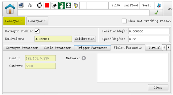
Visual IP: Set to the IP address of the camera.
Port Number: The default port number is 5500.
Connection Status: Display the connection status with the camera server. GREEN indicates a connected status, GREY indicates a disconnected status, and Colorless indicates an unconnected status.
Clear: Clicking this button clears the point information sent by the visual endpoint displayed above the button.
Virtual Conveyor Configuration
Select [Virtual Conveyor] to enter the virtual conveyor parameter configuration interface.
Figure 7-19 Virtual conveyor parameter configuration interface
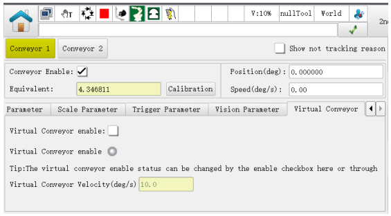
Virtual Conveyor Enable: Control the virtual conveyor ON/OFF.
Virtual Conveyor Enable Status: Display the current status of the virtual conveyor, either Enabled (Green) or Disabled (Grey). Please note that executing the virtual conveyor ON/OFF command will also affect the display of this status.
Virtual Conveyor Speed: Set/display the speed of the virtual conveyor.
For further information on conveyor pulse calibration and on-site configuration steps, please refer to the "ER Series Industrial Robot Conveyor Tracking Operation Manual_RCS2".
----END
7.6 System IP Setup
Network Settings
System IP Setup are only available to users with "Administrator" user type.
Select "Advanced Settings" on the System Home and click on "Network Settings" to enter the system "Network Settings" page. The programming pendant will display the corresponding setting page according to the controller system version.
To ensure normal communication, the parameters in this interface should be set to the correct values according to the actual situation.
Network Settings A
The controller system uses internal bridging for its network card. When any network port is connected to a LAN, the IP addresses of the Programming pendant, OS1, and OS2 cannot be the same as those of other devices on the LAN, otherwise network address conflicts may result in communication anomalies.
Figure 7-20 Network setup interface A
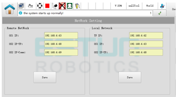
Remote Network Settings: Modify the IP addresses of the OS ends that are currently connected to the programming pendant remotely.
− OS1 IP: IP address of OS1.
− OS2 IP-TP: IP address of OS2.
− OS2 IP-Comm: IP address used for communication with OS2.
Local Network Settings: Only modify the IP addresses of the OS ends that are locally connected to the programming pendant.
− Programming pendant IP: IP address of the programming pendant.
− OS1 IP: IP address of OS1.
− OS2 IP-TP: IP address of OS2.
Network Settings B
The controller system divides the network into internal and external networks. The internal network is mainly for the effective connection between the programming pendant and the controller, while the external network is for the effective connection with external communication. Therefore, when wiring the robot group, only ETH1 or ETH2 needs to be modified according to the application.
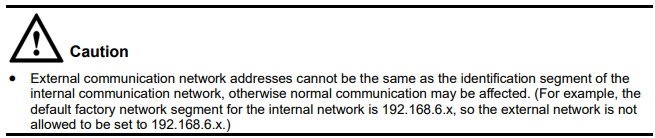
Figure 7-21 Network setup interface B
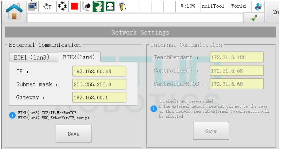
External Communication Network Settings:
− ETH1(lan3): controller-side lan3 port, supports TCP/IP, ModbusTCP, etc.
− ETH2(lan4): controller-side lan4 port, supports VNC, EtherNet/IP, Script, etc.
Internal Communication Network Settings: (default settings cannot be modified, please contact the manufacturer if necessary)
− TeachPendant: IP address of the programming pendant.
− ControllerOS: IP address of the controller.
− ContollerRTOS: IP address of the controller's real-time system.
Modify Subnet Mask and Gateway Rules:
When the teaching pendant is started, the subnet mask and gateway are automatically read and displayed in the interface.
The subnet mask cannot be empty, and the gateway can be left blank.
After modifying the subnet mask and gateway, click the "Save" button to save the changes. Follow the prompts on the interface to restart the controller (as shown in the figure below). After the restart is completed, the modifications will take effect.
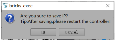
IP Scan
When the controller system is set to type B in the network settings, this function is temporarily unavailable.
In some customer sites, there may be multiple controllers on the same LAN. Without clearing the controller IP configuration, the programming pendant may not be able to connect to the correct controller. Therefore, this function enables scanning of all controllers' IPs on the LAN using the programming pendant, allowing the customer to choose which controller to connect to.
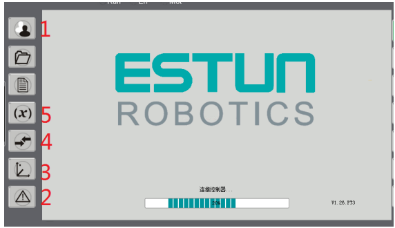
If the programming pendant is unable to connect to the controller after starting up, follow the shortcut keys in the figure below to enter the IP configuration interface.
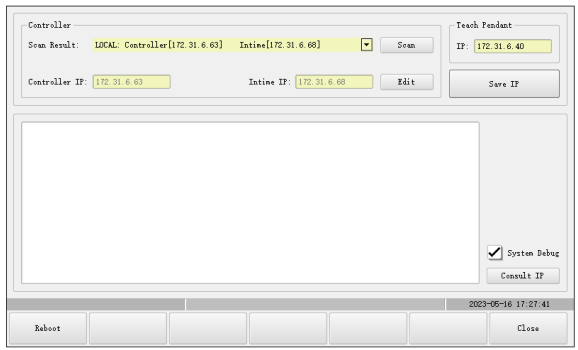
In the IP configuration interface, the IP can be directly edited (with secondary password verification required), or the "Scan" button can be clicked to automatically search for the IP of the current LAN controllers and their corresponding real-time system IPs. Selecting from the drop-down list will automatically fill in the configuration field.
After clicking "Save IP" and successfully saving the changes, click "Restart". After the restart, the programming pendant will be connected to the specified controller.
7.7 Upgrade and backup of programming pendant
Perform the programming pendant upgrading and backup by following the procedures below.
7.7.1 Program upgrading of programming pendant
Following two upgrading methods are available:
1. ESTOOL operation
Upgrade the program directly to the programming pendant system, without checking the "Upgrade the teach pendant while starting up". Load the program in the programming pendant system directly when it is powered on.
2. Upgrading plug-ins through TP
To upgrade the program of the pendant to the controller system, check the "Upgrade the teach pendant while starting up", and load the program in the controller system directly when it is powered on. When this method is selected, the controller system version will be upgraded, and the pendant will also be upgraded automatically and synchronously.
Settings of update mode
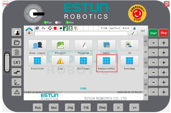
Step 1 Switch the user to the “administrator”, and click the Advanced Settings plug-in group, as shown in Figure 7- 22.
Figure 7-22 Advanced Settings plug-in group
Step 2 Upgrade plug-ins in TP mode, as shown in Figure 7-23.
Figure 7-23 Upgrade plug-ins in TP mode
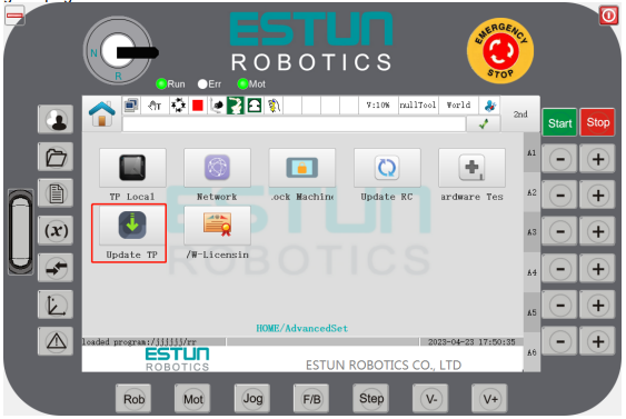
Step 3 Enter the TP update interface as shown in Figure 7-24, and check the "Upgrade the teach pendant while starting up" to enable the synchronous update of the teach pendant.
Figure 7-24 HMI update interface
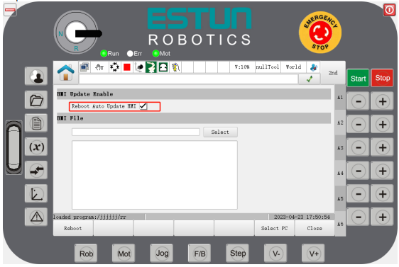
Step 1: Click on the "Select File" button to locate the file that needs to be updated.
Step 2: Click on the "Restart" button and enter your password. After the password is verified successfully, reboot the teach pendant and the restart will take effect.
ESTool update
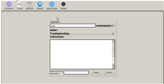
Step 1 Start ESTool. The ways of startup are described in "Start ESTool".
Step 2 ESTool login interface is shown in Figure 7-25.
Figure 7-25 ESTool login interface
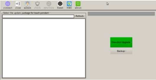
 Step 3 HMI update interface after login, as shown in Figure 7-26. Select HMI function module, insert U disk into the teach pendant, select the file to be updated on the left, and click the update button to update.
Figure 7-26 HMI update interface
Update plug-ins for HMI
Step 1 Switch the user to the “Administrator”, and enter the TP update plug-ins in the Advanced Settings, as shown in Figure 7-24.
Step 2 Select the pendant program file that needs to be updated in the U disk from the list of pendant programs, and click "Select".
Step 3 A prompt message will pop up after the update is finished, as shown in Figure 7-27.
Figure 7-27 Prompt message for HMI update
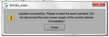
Step 4 Click "Restart", the teach pendant will restart and upgrade to the latest TP version automatically.
Figure 7-28 Procedures for TP update
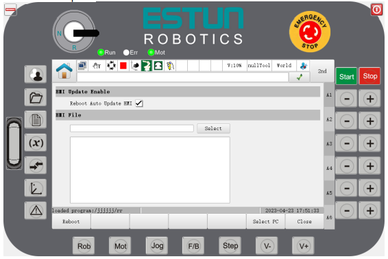
7.7.2 Backup of teach pendant programs
Click the Backup button in Figure 7-26 to export the current teach pendant program to the U disk.
----END
7.8 Update of controller operating programs
7.8.1 Update of controller programs
To update the controller running program, and operate by following the procedures below.
Step 1: Put the controller runtime program (.runtime or .patch format file, which is usually provided by the developer) into the root directory of the USB flash drive.
Step 2: Insert the USB flash drive into the Programming pendant USB port, select Advanced Settings on the System Home and click on the controller update interface as shown in Figure 7-29.
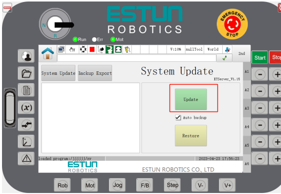
Step 3: Check the "Auto backup in the background" function if required; if checked, the existing system software will be backed up on the controller side before the update, and the backed up system software will be used to restore the system during the system restore.
Step 4: Click on the "Update" button, enter the administrator password to confirm and then you will be prompted if you need to export the existing runtime. Select "Yes" to export the existing runtime from the controller, and select "No" to skip this step and continue to the next step.
Step 5: After selecting the update file, it will automatically update, then wait for the completion of the update.
When updating the controller, and "Auto background backup" is checked, then a backup of the runtime process will appear during the update, as shown in Figure 7-29 and Figure 7-30;
If the actual programming pendant is used and updated from a USB flash drive, then the USB flash drive must be in FAT32 format;
The name of the update package and the path where it is located must not contain Chinese characters,
.Do not power down your system while the system update is in progress, in case the system update is not completed and the system does not function properly.
Figure 7-29 Update interface of controller operating programs
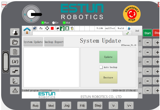
Figure 7-30 Update status display
7.8.2 Controller program restoration
The following steps are used for restoring the controller program:
Step 1: Switch to administrator mode, access the controller upgrade interface, and click "Restore". Enter the administrator password for confirmation. After that, a confirmation dialog box will pop up as shown in Figure 7-31.
Click "Ok" to initiate the restoration request to the controller.
Step 2: Once the controller approves the restoration request, the restoration operation will begin, as shown in Figure 7-32. The programming pendant will disconnect from the controller after the restoration starts.
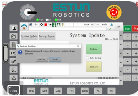
Step 3: Wait patiently for some time. The programming pendant will display a message box indicating that the restoration is about to end, as shown in Figure 7-33. As the message suggests, to ensure data synchronization, the Programming Pendant needs to be restarted. For the virtual Programming Pendant, automatic restart is not possible, so after clicking "OK", the virtual programming pendant will close automatically, and you need to manually reopen and run it. For the actual Programming Pendant, it will restart automatically after you click "OK".
Note
Do not turn off the system power while waiting for the system restoration to complete to avoid system malfunction caused by the restoration failure.
Figure 7-31: Controller program restoration confirmation interface
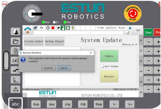
Figure 7-32: Controller program restoration interface
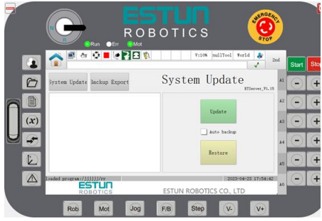
Figure 7-33: Controller program restoration completion interface
7.8.3 Backup export
Step 1: Switch to administrator mode, access the "Controller Upgrade" interface, click "Backup Export", and display the backup export interface as shown in Figure 7-34.
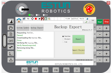
Step 2: Select the export type as required (including: runtime package, project program, and system log), then click "Export". Enter the administrator password for confirmation (if the actual programming pendant is used and no U-disk is inserted, a prompt to insert the U-disk will appear), and then request export to the controller, as shown in Figure 7-35.
Step 3: After the request is approved, the "Export Rename" dialog box will appear. The virtual Programming Pendant also supports selecting the directory to save the export. After setting the export name, click "OK" to begin exporting the corresponding file.
Step 4: After the export is complete, it will be displayed as shown in Figure 7-36.
Note
If using the actual programming pendant, do not remove the U-disk before the export is complete, as it may cause the exported files to be nonexistent or damaged.
Figure 7-34 Backup export interface
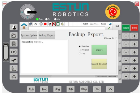
Figure 7-35 Request export interface
7.8.4 Project Import
Step 1: Put the prepared project file (.project format file, which can be obtained by using the backup export function to export the project program. If it needs to be made under special circumstances, please refer to the Operation Manual for ER Series Industrial Robot Controller Upgrade) into the root directory of the USB disk and insert the USB disk into the programming pendant.
Step 2: Switch to the administrator user and enter the "Controller Upgrade" interface. Click "Backup Export" and then click "Import Project". After entering the administrator password to confirm, the interface shown in Figure 7-37 will be displayed, prompting that importing the project will overwrite the existing project. You can choose to export the existing project by clicking "Yes". The process is the same as exporting the project program. After the export is completed, the project program file dialog box will be entered. If you click "No", you will directly enter the dialog box for selecting the project program file.
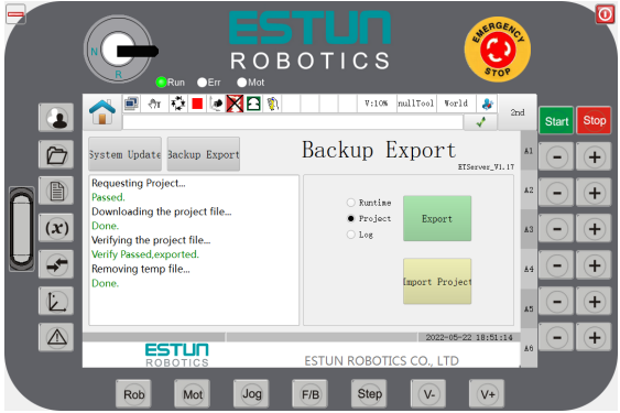
Step 3: Select the imported project program, and the import will begin. After the import is completed, the prompt "Import successful" will be displayed. Please refresh the project, as shown in Figure 7-38.
Step 4: Click the project button on the right to enter the project interface. Click "Refresh" to display the imported project.
Figure 7-37: Project import interface
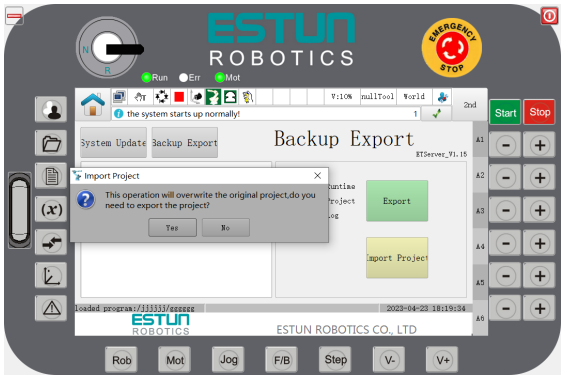
Figure 7-38: Project import completed interface
----END
7.9 Reach by one-click
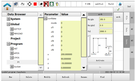
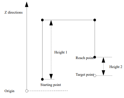
Reach by one-click. With this function, the robot moves from the current point to the target point in an arched path. The user interface is shown in Figure 7-39.
Figure 7-39 Interface of Reach by One-click
Note
⚫ This function is currently available only on SCARA models.
⚫ Reach by one-click. It is applicable only to position variables in the world coordinates.
⚫ When being activate d, the parameter configuration of Reach by One-click will become valid.
⚫ To use this function, press and hold the hand switch in manual mode before performing motion operations.
⚫ By pressing and holding the button, the robot will stop after moving to the target point. If the button is released halfway, the robot will stop motion immediately, and continue to move toward the target point by pressing such button again. Where: Height 1 represents the height of the vertical lift from the starting point along the z-axis; Height 2 represents the vertical height of the target point. The arched path is shown in Figure 7-40.
Figure 7-40 Arched path
7.10 Calibration of tool coordinates
Perform the calibration of tool coordinates by following the procedures below.
Step 1 Enter the program data interface, and click the tool coordinates to be calibrated in the global scope, i.e. TOOL0, as shown in Figure 7-41.
Figure 7-41 Variable interface of the tool coordinates
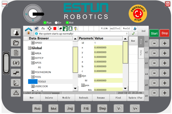
Step 2 Click "Modify" to enter the preview interface of reference coordinate system, as shown in Figure 7-42.
Figure 7-42 Preview interface of reference coordinate system
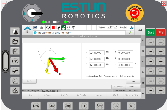
Step 3 Click "Settings" and enter the calibration method selection interface of the reference coordinate system, as shown in Figure 7-43.
Figure 7-43 Select the way of calibration
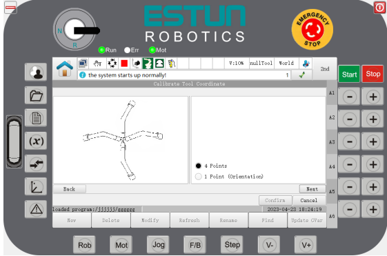
Step 4 Select the way of calibration and perform calibration to the offset or posture. [4-point Calibration]
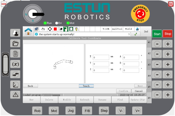
1. Select the “4-point Calibration”, which means that you need to calibrate tool offset by teaching 4 different postures of the same point. The, click "Next". Move the robot TCP to a position and click "Teach", as shown in Figure 7-44.
Figure 7-44 Teaching the first point
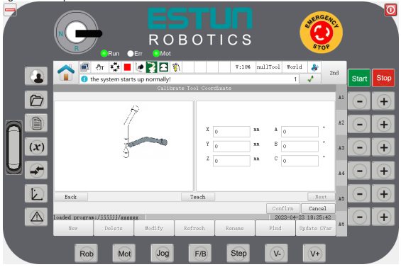
2. Then, click "Next" to change the posture of the robot, and click "Teach", as shown in Figure 7-45.
Figure 7-45 Teaching the second point
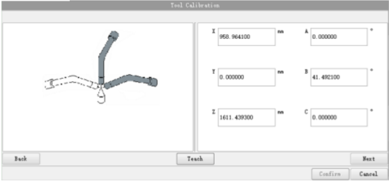
3. Click "Next" to change the posture of the robot, and click "Teach", as shown in Figure 7-46.
Figure 7-46 Teaching the third point
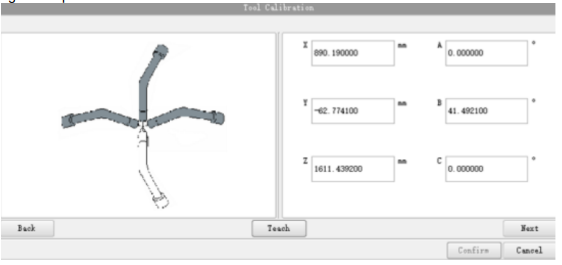
4. Click "Next" to change the posture of the robot, and click "Teach", as shown in Figure 7-47.
Figure 4-47 Teaching the 4th point
5. The accuracy error after this teaching will appear. User can continue to save the result or re-calibrate as needed.
6. Click "Next" to get the calibrated value, as shown in Figure 7-48.
Figure 7-48 Calibration result of tool coordinates
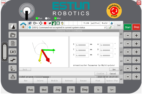
7. Click "OK" after it is confirmed to be correct. The modification is finished. [1-point Calibration]
Select "1-point Calibration" to indicate the posture of the next calibration tool. It can only calibrate the posture change if a tool in an axis direction under tool coordinates.
1. Click "Next". Make the direction of the robot's end in parallel to the Z axis, and click "Teach", as shown in Figure 7-49.
Figure 7-49 Teaching a point on the Z axis
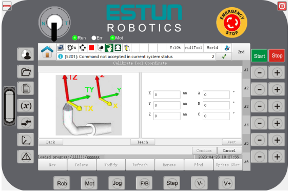
2. Click "Next", and the result of the posture calibration of tool coordinates will appear, as shown in Figure 7-50.
Figure 7-50 Posture calibration results of tool coordinates
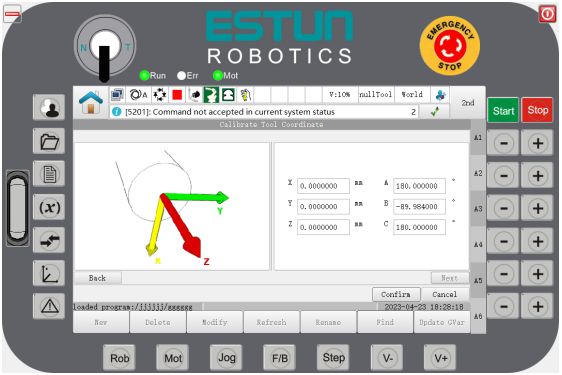
Step 5 Click "OK" after it is confirmed to be correct. The modification is finished, as shown in Figure 7 51.
Figure 7-51 Tool coordinates variable undergoing successful posture calibration
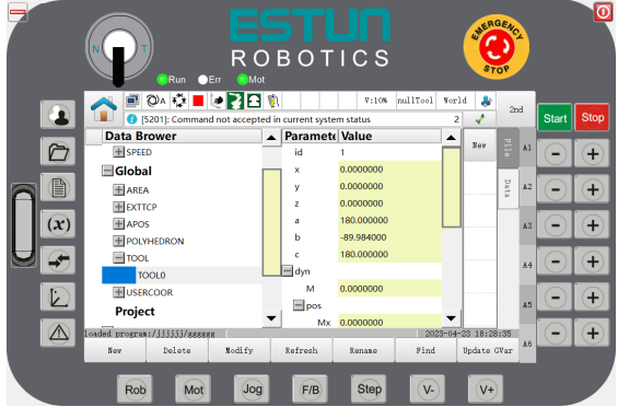
----END
7.11 Calibration of user coordinates/external tool coordinates
Note
In this section, the calibration operation of the user coordinates is illustrated.
The calibration method for external tool coordinates is the same as the user coordinates. When modifying, the default name of the user coordinates is USERCOOR, while the default name of the external tool coordinates is EXTTCP.
Perform calibration to a user coordinate system by following the procedures below
Step 1 Enter the program data interface, and click the user coordinates to be calibrated in the global scope, e.g. USERCOOR1, as shown in Figure 7-52.
Figure 17-52 Interface of user coordinates variable
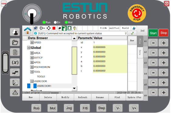
Step 2 Click "Modify" to enter the preview interface of user coordinates, as shown in Figure 7-53.
Figure 7-53 Preview interface of user coordinates
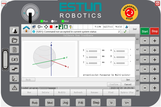
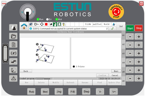
Step 3 Click "Settings" to enter the calibration method selection of user coordinate system.
There’s only the "3-point calibration method" available currently, as shown in Figure 7-54.
Figure 7-54 Select the way of calibration
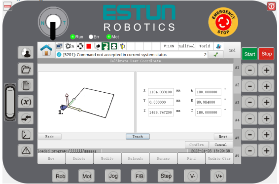
Step 4 Click "Next" to start teaching the coordinates at the origin, and move the robot to the origin of the user coordinates. By clicking "Teach", the interface will record the coordinates of the origin (the first point), as shown in Figure 7-55.
Figure 7-55 Teaching the origin
Step 5 Click "Next" to move the robot to any position on the X-axis of the user coordinate system. Click "Teach", the interface will then record the coordinates of the second point, as shown in Figure 7-56.
Figure 7-56 Teach a point on the X axis
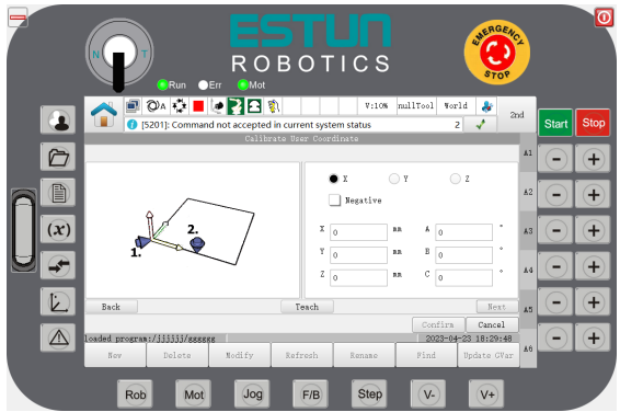
- If X is checked: it means that the x-axis is selected and only the xy-plane or xz-plane can be selected.
The same applies if Y/Z is selected.
- If negative direction is checked: it means movement in the negative direction.
Step 6 Click "Next" to move the robot to any position on the XY plane of the user coordinates. Clicking "Teach", the interface will record the coordinates of the third point, as shown in Figure 7-57.
Figure 7-57 Teaching any point on the XY plane
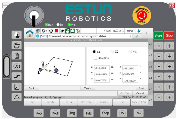
Step 7 Click "Next" and return to the preview interface of user coordinates, as shown in Figure 7-58.
Figure 7-58 Calibration result
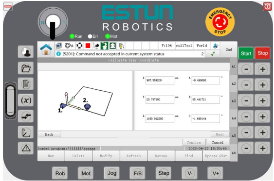
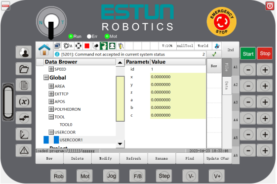
Step 8 Click "OK" after it is confirmed to be correct. The modification is finished, as shown in Figure 7 59.
Figure 17-59 User coordinates variable undergoing successful calibration
----END
7.12 External TCP functions
Function overview
Usually, the tool is installed on the robot, and perform the specified tasks by tracking the motion of robot. In some specific applications such as gluing, it is required to install the glue gun (tool) at a position outside the robot, while the workpiece needs to be fixed on the robot for gluing. Such kind of tool installed outside the robot and in a fixed position is called External TCP.
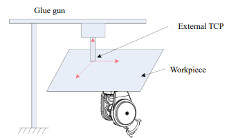
Calibrate the external TCP before using the external TCP functions. For details, please refer to "7.11 Calibration of user coordinates/external tool coordinates".
The external tool coordinates may be selected in the jog reference coordinate system. When the external tool coordinates is selected as the reference coordinate system, the jog position and posture are relative to the external tool coordinates. The jog position under the external TCP is similar to the jog position under the user coordinate system, and both move along the X, Y, and Z directions of the reference coordinate system. The difference between the jog posture in the external tool and the jog posture in the user coordinate system: for the jog posture in the user coordinate system, the TCP point does not move, while the posture rotates around the TCP point. For the jog posture of the external tool, the TCP point rotates around the external tool coordinates.
In MovL and MovC commands, the reference coordinate system can be selected as external tool coordinates. The current reference coordinate system can also be set as external tool coordinates using the command SetExternalTCP. When the external TCP is used to teach linear and circular motions, teach 2 points in a linear mode, and 3 points in an arc mode.
Note
The posture point stored in teaching can be the description of the TCP point relative to the external TCP. The motion of is relative to the external TCP coordinates.
For example, when external TCP functions are used, if the teaching origin and endpoint of the workpiece is attached to the external TCP origin, the contour of the workpiece is a straight line, irrespective of the changes of posture of the teaching origin and endpoint. When linear motion commands are used, the contour of the workpiece always moves along the external TCP origin. The motion speed is the speed of the workpiece relative to the external TCP coordinates.
Way of use
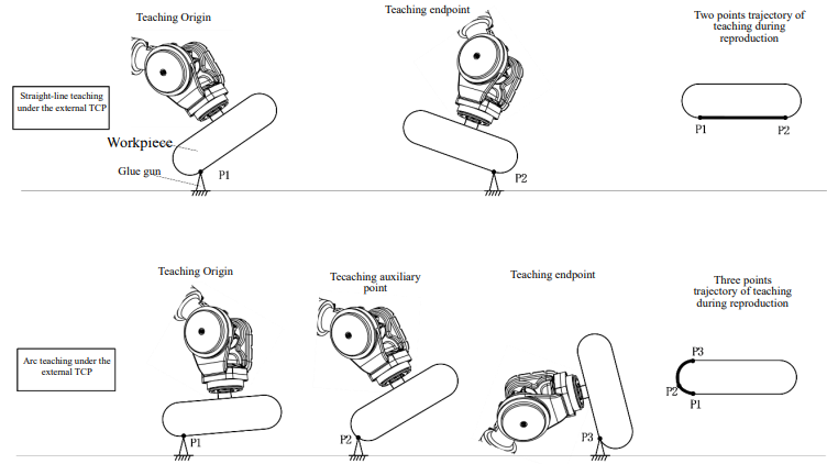
7.13 Single-point alignment coordinate axis
Function overview
In some applications, the robot needs to rotate the posture so that a certain axis or full axis in the tool coordinates can accurately be perpendicular or parallel to the specified plane. In this case, the Single-point Alignment Coordinate Axis would satisfy this requirement. Users may teach the target posture of the robot roughly, and then perform the precise gesture adjustment by using the Single-point Alignment Coordinate Axis so as to achieve the final target posture.
Way of use
Step 1 Enter the Jog Management group in the Home; click "Tool Alignment", and enter the operation interface of "Single-point Alignment Coordinate Axis", as shown in Figure 7-60.
Figure 7-60 Operation interface of single-point Alignment Coordinate Axis
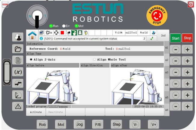
Step 2 Select the "Alignment Type".
Single-axis alignment: The alignment will be performed only to the Tz direction of tool coordinates and the nearest coordinate axis of the specified coordinates.
Full coordinate system alignment: Align each axis (Tx, Ty, Tz) of tool coordinates with the specified coordinate system.
Note
"Alignment" is an operation that will not change the current TCP position, but making the TCP be parallel to the axis of the specified coordinate system only by changing the posture.
Step 3 Click "Activate".
To cancel the alignment operation, click "Disable".
Step 4 Perform the alignment by clicking the "+/-" key corresponded to "GO" in the upper right corner.
Figure 7-61 Operating interface upon activation of single-point alignment coordinate axis
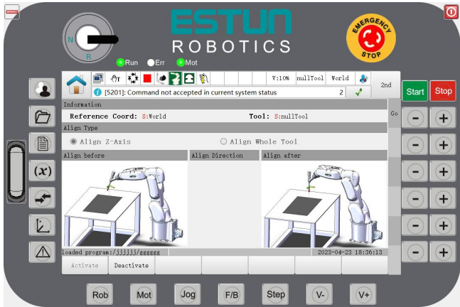
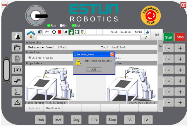
Step 5 A pop-up window means that the alignment is successful, as shown in the figure below.
----END
7.14 Servo management
Function overview
Users can directly clear and reset servo drive alarms, set some PN parameters, view servo version information, and perform batch backups and restores through the interface of the programming pendant

Way of use
Enter the General Settings group in the Home; click "Servo Management", and then enter the "Servo Management" operation interface, as shown in Figure 7-62.
Clear Servo Alarms
The "Clear Servo Alarms" operation interface is displayed by default when first entering the Servo Management page, as shown in Figure 7-62. You can also click the bottom function button to switch to the "Clear Servo Alarms" operation interface.
Figure 7-62 Servo alarm clearing
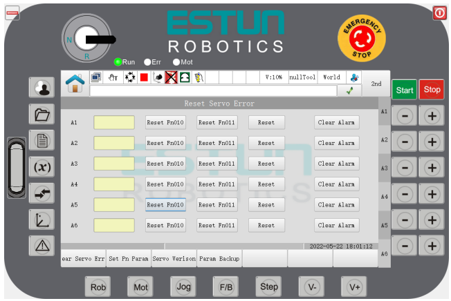
Click "Reset Fn010" and "Reset Fn011" to clear the servo alarms associated with the absolute encoder (A.45, A.46, A.47, A.48, A.51).
Click "Reset" to clear the current servo alarm of the right axis.
Click "Clear History Alarm" to clear the history alarm of the right axis.
Set PN Parameters
Click the "Set PN Parameters" function button at the bottom to enter the "Set PN Parameters" operation interface, as shown in Figure 7-63, which initially displays the PN parameters of Axis 1.
Figure 7-63 Setting PN parameters
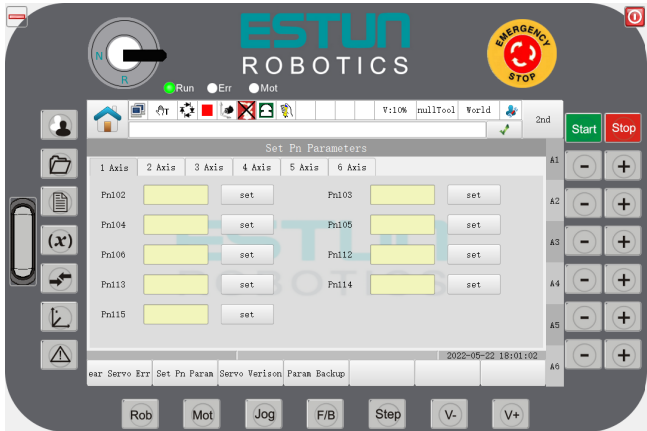
Click the "Set PN Parameters" function button at the bottom to get the PN parameters of current axis on the interface.
Click the corresponding axis number tab to get the PN parameters of the corresponding axis.
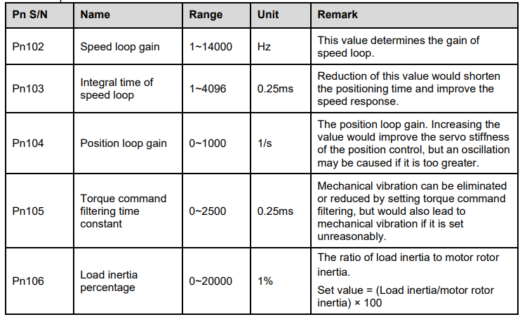
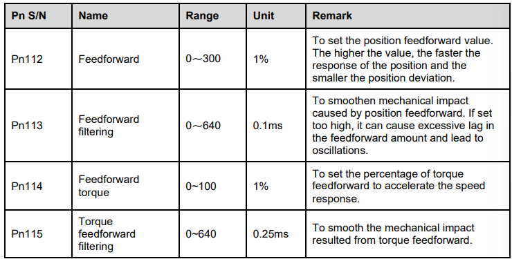
Clicking the "Set" button for the corresponding PN parameter pops up an input box. After entering a value, click the "OK" button to send the input value to the servo. After the setting is done, the current PN value is displayed in the corresponding PN parameter textbox.

⚫ Disable the servo enable signal.
⚫ Familiarize yourself with the servo parameter setting method, including parameter range, meaning, and other information.
Table 7-1 Pn parameters to be settable
Viewing Servo Software Version
Clicking the "Version Information" button at the bottom will take you to the "Servo Software Version" screen, as shown in Figure 7-64.
Figure 7-64 Servo Software Version
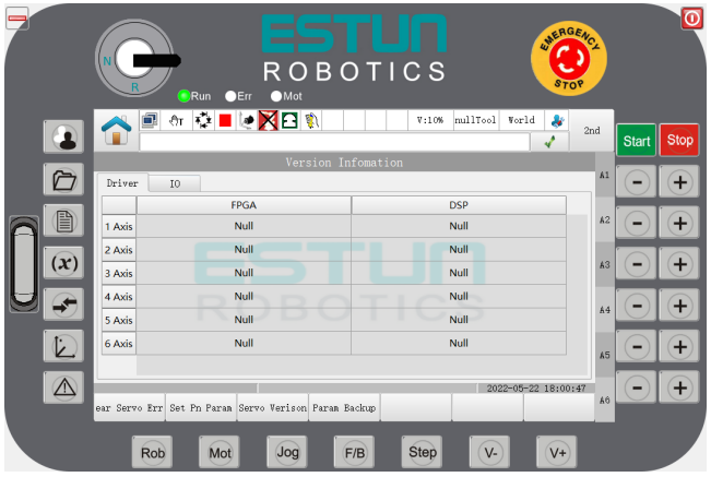
After the programming pendant is started normally, clicking the "Version Information" button at the bottom will obtain the servo software version and display it on the screen.

Servo Parameter Backup & Restore
Clicking the "Backup & Restore" button at the bottom will take you to the operation screen for "Servo Parameter Backup & Restore," as shown in Figure 7-65.
Figure 7-65 Servo parameter backup & restore
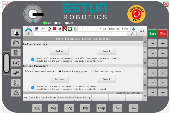
Clicking "Backup" will prompt for a password. Use the administrator password to confirm the operation. After the password is verified, the controller will locally backup the current portion of the Pn parameters. Note that the backup file will overwrite the original backup file.
The restoration of servo parameters can be divided into two types: restoring user-backed up parameters and restoring factory-backed up parameters. Select the type of backup to restore using the radio button.
Restoring user-backed up parameters: i.e., restoring servo parameters backed up or imported by the
user.
Restoring factory-backed up parameters: When the machine is delivered, a servo factory parameter backup file is provided for each model. Restoring this backup file will restore the parameters to the servo.
After selecting the backup type using the radio button, click "Restore" and enter the password. Use the administrator password to confirm the operation. After the password is verified, the controller will execute the restore operation.
Insert a USB disk and click "Export" to download the user backup parameter file to the root directory of the USB drive.
Insert a USB disk and click "Import". Enter the password, use the administrator password to confirm the operation, and after the password is verified, select the imported servo backup parameter file.

7.15 Use of 2D vision
Function overview
Robot vision refers to the system that provide the robot with visual perception function. It is one of the key parts of the robotic system. Robot vision can obtain a 2D image through a vision sensor, make analysis and interpretation using a vision processor, and then convert it into a symbol, so that the robot to recognize an object and know its location exactly.
Way of use
Step 1: From the System Home, select "General Settings > Visual Settings" to enter the Visual Settings page, as
shown in Figure 7-66.
Figure 7-66 Setting interface of 2D vision
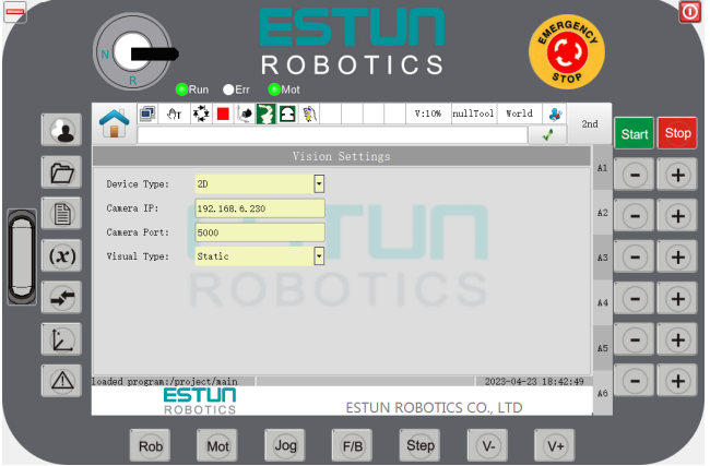
Step 2: Select "2D" for the "Camera Device Type" option.
Step 3: Fill in the "Camera IP" and "Camera Port Number" according to the actual parameters, which are set to 192.168.6.230:5000 by default.
Step 4: Currently, only static visual types are supported.
Parameter Description
Camera Device Type: Sets the 2D or 3D view.
Allowed Values: 2D, 3D, 2D client.
Camera IP: The default IP is 192.168.6.230.
Camera Port Number: The default value is 5000.
Visual Type: Divided into dynamic and static types, only static visual types are currently supported.
Visual Commands
The visual commands list is shown in Figure 7-67.
Figure 7-67 List of visual commands
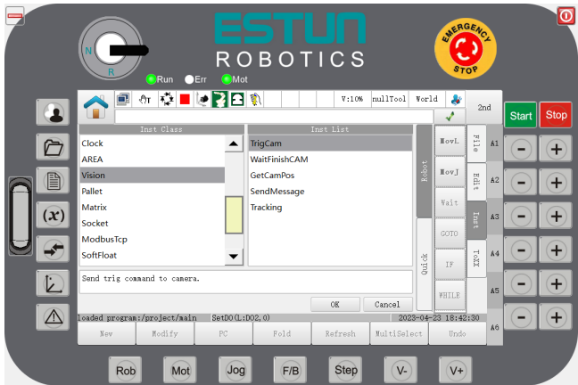
TrigCam
This is the command for triggering the camera shooting

WaitFinishCAM
This is the command for waiting for the camera to finish shooting.

GetCamPos
This is the command for getting the camera position.

7.16 Use of 3D vision
Function overview
Robot vision refers to the system that provide the robot with visual perception function. It is one of the key parts of the robotic system. Robot vision can obtain a 3D image through a vision sensor, make analysis and interpretation using a vision processor, and then convert it into a symbol. It is used to set the robot's variables, position points, and IOs. Also, it needs to get the robot's variables, position points, IOs, current position and other commands, to enable the robot to recognize objects and be controlled by visual logic.
Usage I
The robot is the client, while the vision device is the server.
Step 1: Go to the System Home and select "General Settings > Visual Settings" to enter the 3D visual settings interface as shown in Figure 7-68.
Figure 7-68 3D vision setting interface
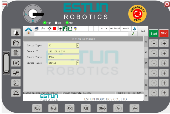
Step 2: Select 3D for the camera device type.
Step 3: Fill in the camera IP and port number as per the actual parameters. It is defaulted as 192.168.6.230:6000
Note
The vision type does not work in 3D mode.
Step 4: Send a character string to the vision settings by using the command SendMessage. The content of the character string can be defined by the user. For example, sending the string "ScanReque" to the camera can be achieved by executing SendMessage("ScanReque",1).
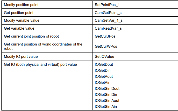
Vision obtains 3D images of the environment using the sensor, makes analysis and parsing, and then converts them into vision commands to set or get robot variables, position points, IOs, etc.
The vision commands on the robot are listed in Table 7-2.
Table 7-2 Vision commands
Usage II
Using robot as the server, and the vision device serves as the client. The robot server is configured as follows:
IP: 192.168.6.63 (controller’s IP address)
Port: 5000
Step 1 Establish the connections.
1. Controller internally start the python script to create the server-side.
2. Configure the client device to make it connect to the robot. (Ping the controller IP 192.168.6.63)
3. Configure the client device to use the above connection parameters.
4. Establish a connection with the server. (The client should send a read and write request to the server every 10 seconds at the moment to keep the connection as a heartbeat)
Step 2 The vision client then sends commands to the server.
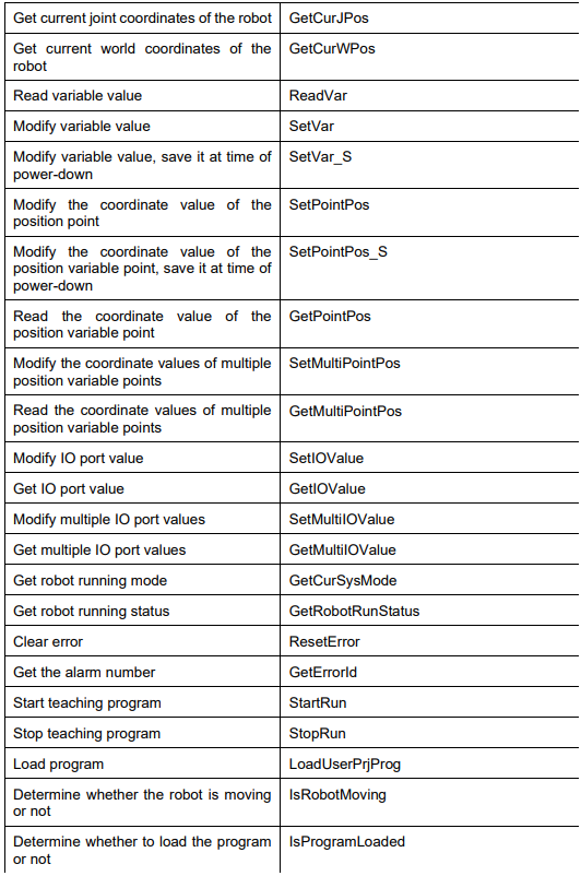
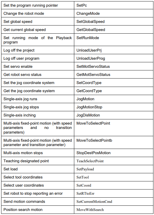
The vision commands sent to the robot are listed in Table 7-3.
Table 7-3 Vision commands
----END
7.17 ModbusTCP
Function overview
ModBusTcp protocol interface is a communication mode in which an external logic controller (PLC, etc.) communicates with the robot via the standard industrial bus protocol (ModBusTCP), and reads and writes the virtual IO port of the robot. The robot can interact with external devices through ModBusTCP without additional expansion of IO ports.
Estun robot controller, as a server, provides the following functions to external control device through ModbusTCP protocol:
Access and control virtual I/O
Read the current robot running status
Start/stop the program using the control word, enable the robot, load/log off the program, set the global speed
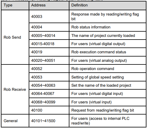
The ER series robot encapsulates a layer of data structure in the ModBusTCP holding register, as listed in Table 7-4.
Table 7-4 ModBusTCP Holding Register Data Partitioning Table
Way of use
The ModBusTCP interface of ER series robots is configured as follows:
IP: 192.168.6.68 (real-time system IP address)
Port: 502
Cycle of collection >50ms
Response timeout>100ms
Heartbeat time <10s
Step 1 Establish the connection.
1. Configure the client device to make it connect to the robot. (Ping the real-time system at IP 192.168.6.68)
2. Configure the client device to make it use the above connection parameters.
3. Establish a connection with the server. (The client should send a read and write request to the server every 10 seconds at the moment to keep the connection as a heartbeat)
Step 2 Read and write SimIO.
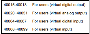
According to the table below, the virtual output is SimOutput. The client should read the value of the corresponding register, and map it to the input of the external device. The virtual input is SimInput. The client should write the value to the corresponding register, and then map it to the output of the external device.
Table 7-5 SimIO mapping table
Step 3Read the robot status.
The 40004 register of the server is of the robot status word. 40002 is the current global speed of the robot.
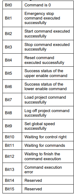
The following lists the meaning of each bit of the robot status word:
Table 7-6 Meaning of robot status word
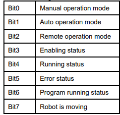
The client can read the corresponding Bit through the mask to get the robot status.
Step 4 Send the control commands.
Send commands such as starting/stopping program, loading/logging out program, and setting global speed to the robot as per the procedures below.
1. Reset the command execution interface by writing the command control word 40052 as 0, and 40100 as 0.
2. Write 40100 as hexadecimal 0x11.
3. When the value of 40003 is 0x11, set the corresponding Bit of the control word according to the table below.
4. When the corresponding bit of the command execution status word 40019 is 1, it indicates that the command is executed successfully.
5. When 40100 is 0, it means that 40019 is reset.
Table 7-7 Data sheet of robot command execution system
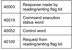
Table 7-8 Meaning of robot control word
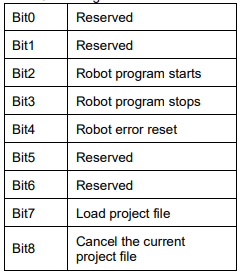
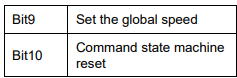
Table 7-9 Meaning of robot command execution status word
----END
7.18 Lockup and unlock
1. The robot lockup refers to the time range set for the robot's use authority by using this application program. The robot can operate normally in such time range. If it goes beyond such time range, the robot will then stop working by locking the motion.
2. The robot can be in four lockup states: The locked state of robot, the unlocked state in stage 1, unlocked in stage 2, unlocked in stage 3, and unlocked indefinitely.
3. No lockup setting is made for the robot at time of delivery, but be defaulted to unlock indefinitely. Once it has been locked up, the motion and other related operations cannot be performed.
4. The number of days of lockup are to be set and cleared by the manufacturer by entering a dynamic password to log in. The unlocking operation can be done by the user after getting the unlocking key from the manufacturer.
5. User role or higher is required for this operation.
Turn on lockup management application
Step 1: Go to the System Home and select "Advanced Settings > Lock Management" to enter the Robot Staged Lockup Management application interface, as shown in Figure 7-69.
Figure 7-69 Open Lockup Management application
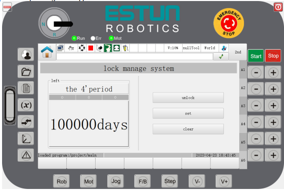
Remaining: Display the current period type and the remaining days of the current period. If the "special period” is displayed for the permanent unlocking, the remaining days are "indefinite period";
Unlock: Open the period unlocking interface. This operation can be finished by users.
Setting: Open the interface for setting the period of days. The operations in this interface can only be performed by the manufacturer’s personnel after entering the dynamic password
Clear: Open the permanent unlocking robot setting interface. The operations in this interface can only be performed by the manufacturer’s personnel after entering the dynamic password
----END
Set lockup period
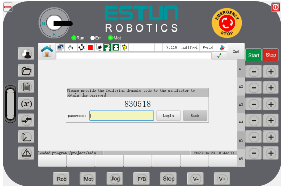
Step 1 Open the lockup management application interface; click the "Clear" key. The teach pendant is displayed as shown in Figure 7-70. According to the prompt dynamic code, the manufacturer's personnel can then obtain the login key and log in.
Figure 7-70 Login
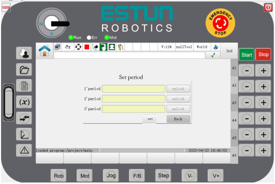
Step 2 After logging in, as shown in Figure 7-71, enter the restricted number of days for stages 1, 2, and 3, and click the "Set" key to invalidate the set days.
Figure 7-71 Setting of period
Note
⚫ After the robot software is installed at time off delivery, and if the lockup is not configured, the lock will be not restricted by default, and all the functions can be used permanently.
⚫ All the days for the three stages need to be filled in, and be invalid after setting.
⚫ After setting, the stage 1 lockup will be valid. The starting time is the current time of unlocking.
----END
Unlocking period
Step 1 Enter the staged lock management application interface, click the "Unlock" button, and the teach pendant will display as shown in Figure 7-72. Then, provide the machine code and the number of stages to be unlocked to the manufacturer to get the unlocking key. The machine code consists of two parts, and the format is: fixed codedynamic code.
Figure 7-72 Unlocking period
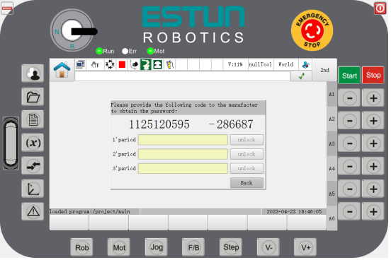
Step 2 After unlocking the appropriate period, the period will then become valid. You can refresh to view the current remaining days in the corresponding interface.
Note
⚫ The current number of days after unlocking will become valid immediately. The start time will be the current unlocking time.
⚫ If unlocked in an early time, only the number of days in the current period will be valid, and the days in the previous period will be invalid by default.
----END
Clear lockup period
Step 1 Enter the staged lock management application interface, click the "Clear" key, and the teach pendant will display as shown in Figure 7-73. According to the prompt dynamic code, the manufacturer's personnel can then obtain the login key and log in.
Figure 7-73 Logging in Lockup Clearing Interface
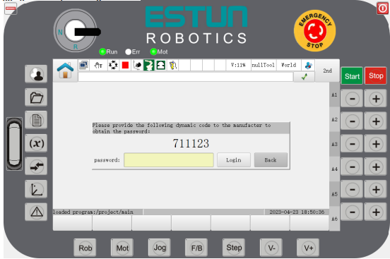
Step 2 Log in the lockup clearing setting interface, as shown in Figure 7-74. According to the prompt machine code, the manufacturer's personnel is provided with the clearing key.
Figure 7-74 Lockup clearing setting
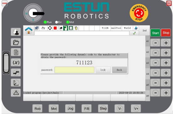
Step 3 After the lockup function is cleared, the robot enters an unlocked state indefinitely. You can refresh and view the current period in the interface of remaining days with no "Special Period" displayed, and the remaining days are "Indefinite".
----END
7.19 SoftFloat functions
Function overview
SoftFloat functions are used for extracting workpieces from the die-casting machine. The SoftFloat functions of the robot works to turn the robot into a flexible body. The robot can move in response to changes in the external force under the action of external forces to prevent damage to the robot and workpieces resulted from the rigid contact. This allows the realization of linear SoftFloat functions in the specified direction. The robot can perform the linear motion following the die-casting machine ejector rod.
When the workpiece is gripped by the robot and the machine is performing feeding/blanking operations, there is a difference between the gripping position and the final position of the rough workpiece. Linear SoftFloat function works to change the robot from a rigid state to a flexible state without using external sensors or adding a mechanical construction. The end of the robot can move in a straight line in the specified direction under the actions of the external force, and fit the workpiece well to avoid collision and friction. The function is used in die-casting and other workpiece feeding/blanking operations.
When SoftFloat is started, the motion speed of robot is determined by the external force. The greater the external force, the faster the robot will move.
SoftFloat function can be started by following mode.
− Auto running (single-step, continuous)
− Manual running (single-step, continuous)
Caution
⚫ After SoftFloat is turned on, it will be turned off in case of following conditions.
⚫ When using SoftFloat functions, please specify the correct SoftFloat direction to ensure that it is consistent with the moving direction of the workpiece.
⚫ After SoftFloat is turned on, the following situations occur, and SoftFloat functions are turned off.
→The controller reports an error
→When the stop button or E-stop button is pressed
→SoftFloat is turned on for more than the waiting time of system settings
⚫ The starting and closing commands of SoftFloat need to be used together, of which the starting command shall be set before the closing command. If you want to execute multiple groups of SoftFloat functions in a teaching program, multiple sets of start and ending commands shall be set. The control system will report an error when the following commands are set.
→Only executing the SoftFloat starting command
→Only executing the SoftFloat closing command
→Executing the SoftFloat closing command before the starting command
→Executing the SoftFloat starting command continuously
⚫ The control system will report an error if the action commands are inserted into the SoftFloat starting and closing commands.
⚫ Never use SoftFloat functions near the singular point.
⚫ Stop the SoftFloat after the external force is removed, in such a way that the robot will stop without producing vibration.
⚫ If the last motion command of the SoftFloat starting command contains transition information, no transition processing will be performed.
When SoftFloat is turned on, the collision detection and maximum torque detection functions are turned off, which will be restored when SoftFloat closes or an error is alarmed after SoftFloat functions is turned on.
The SoftFloat direction can be set by following the procedures below:
Before extracting workpieces using SoftFloat, confirm whether the SoftFloat direction is set correctly. When tool coordinates are selected as the reference coordinate system, the linear motion direction will be the direction of tool coordinates direction selected at the start point of SoftFloat. The direction of SoftFloat tool coordinates is the same as the direction when the robot is in jog operation. When TOOL is selected as the reference coordinate system, the coordinate system number shall be nullTool. When the Y direction is selected for SoftFloat, the direction of the linear SoftFloat is shown as follows:
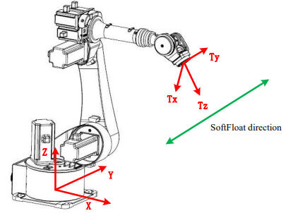
The flexibility effect will the best when the direction of SoftFloat is set in parallel to the tangential direction of the horizontal rotation of the robot's force point around the Z-axis of the world coordinates; when the angle θ is greater than 60 degrees, the linear SoftFloat will report an error. The angle θ is the angle between two straight lines in space. It is illustrated as follows:
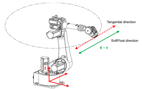
The flexibility will be better if the angle between the tangential direction is parallel to the SoftFloat direction.
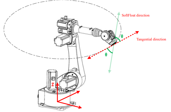
The flexibility will be poor if the angle between the tangential direction and the SoftFloat direction is larger.
Application example
The extraction of workpieces from the die-casting machine will be taken as an example. The field application of SoftFloat can be in following process:
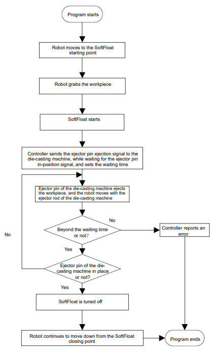
1. When the program runs to the starting point of SoftFloat, the workpiece will be gripped first.
2. After the SoftFloat is turned on, the controller sends DO signals to the die-casting machine, while waiting for the DI signal input of the die-casting machine ejector in-position signal and setting the waiting time;
3. When the die-casting machine receives the DO signal, the die-casting machine ejects the ejector rod, and the robot can move by following the ejector pin; When it goes beyond the set waiting time, the controller alarms;
4. The SoftFloat ends when the controller receives the ejector in-position signal.
5. The robot continues to move down from the position where the SoftFloat ends.
Example of teaching:

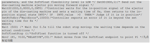
7.20 9-point Calibration
Function overview
9-point calibration is designed for the field applications of ESTUN robots equipped with camera vision device. With this function, the camera can send directly the pixels of the object being shot. After the robot controller receives the camera pixels, they can be converted into the position points under world coordinates internally. The robot is allowed to grasp accurately the target object based on the position points converted.
Way of use
Step 1: On the System Home, select "User Applications > 9-point Calibration" to enter the corresponding operation interface, as shown in Figure 7-75.
Figure 7-75 Operating interface of 9-point calibration
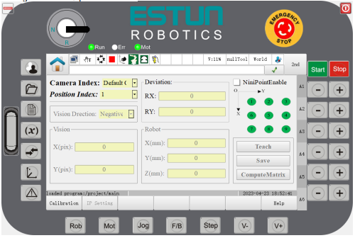
Step 2 Set the vision coordinates and robot coordinates.
Put the calibration paper under the camera, and make sure that the 9 calibration points are within the shooting range of the camera. After shooting, 9-pixel position points will be produced, which shall be recorded. Then operate the robot manually, move the TCP points of the robot to positions 1~9 on the calibration paper in turn. Each time when the robot moves to a calibration point, enter the corresponding pixel coordinates into the visual box, and then click Teach to display the robot coordinate points, and finally click “Save” button. This shall be done from 1 to 9 on the calibration paper
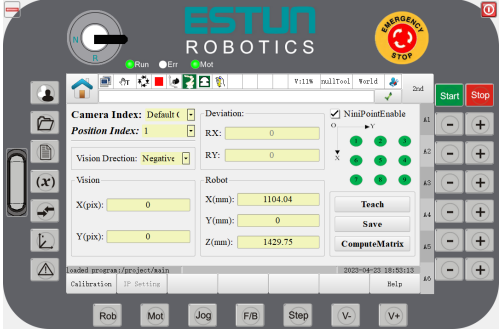
1. Select the corresponding camera; each camera shall have the appropriate calibration parameters.
2. The initial interface is not operable; check the upper right corner to enable 9-point calibration function.
3. Operate the teach pendant manually to move the robot to calibration point 1; select point 1 and input manually the pixel position corresponded to the calibration point 1; keep the robot TCP point coincident with point 1 on the calibration paper, and then click to teach the current robot coordinate point. Click “Save” key.
4. Repeat the above operation, select calibration points 2~9 in turn, and input the pixel position points corresponded to the calibration points;click “Save” after each time of input.
Note
Selection of calibration direction: Select the positive direction when the Z direction of the camera working coordinate system is the same as the Z direction of the world coordinate system, the positive direction is selected here; and select negative when the Z direction of the camera working coordinate system is opposite to the Z direction of the world coordinate system.
After each point has been taught, click the “Save” button.
Step 3 Compute the matrix.
Click the “Compute” button after setting the visual pixel position point and robot coordinate point. The computation error is displayed at RX and RY, and the normal error is within ±0.1. After computation, keep the 9-point calibration enable in the enabled state. Then, send the shot target object point to the robot end using the camera to observe if the robot can move to the target object correctly.
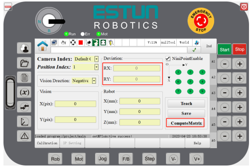
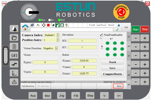
Calibration drawings
The serial number of the calibration point of the vision and robot must be the same as the figure below.
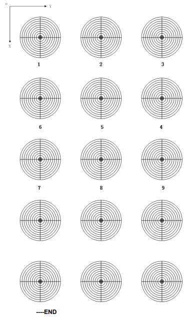
7.21 Multi-station Reservation
Function overview
With this function, the robot can complete tasks on up to 4 stations without intermittent.
Multi-station Reservation function works to bind each station in the robot working area to different input ports, and assign these input ports with the functions of starting and stopping, and then the user can enable the robot to execute the station program bound to it automatically by entering effective signal to the input port. Also, by using this function, user can start the programs on the corresponding tooling in turn according to the sending order of the signals.
The figure below illustrates a working example of a robot: its working sequence is tool 1, tool 2 and tool 3; the jobs performed on each tool are program 1, program 2 and program 3.
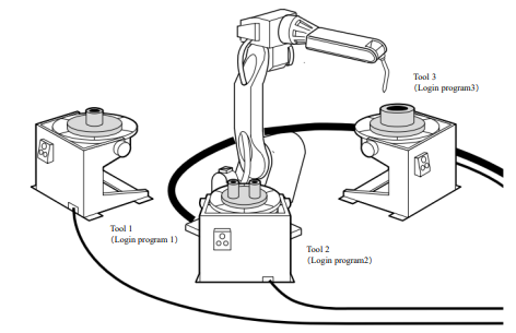
Each of the three toolings process the different workpieces, corresponding to different processing procedures. There’re following two effects when starting it under Playback mode, assuming that the procedures are program 1, program 2, and program 3:
When there’s no program executed currently, user sends signal to tool 1, and the robot will automatically load and run program 1. The starting mode of tools 2 and 3 is the same as the tool 1.
The program currently being executed by the robot: Assuming that program 1 is currently being executed, and workpieces are prepared for tools 2 and 3, the user first sends the starting signal to tool 3, and then the tool 2. At this moment, as the robot is executing the tool 1, then the system will record the appointment waiting status of tools 3 and 2 in turn. When program 1 is executed, the robot will execute program 3 first, and then the program 2. The whole appointment process is finished by this moment.
When the robot operates, the user can check the working status and IO signal of each station using the teach pendant.
Way of use
To use this function correctly, user needs to complete the following tasks:
The program of each station has been edited correctly. For the editing method of the program, please refer to 4.2 Program editing.
The Start button located on the tooling of each station can be used properly.
Step 1 Click "Multi-station Reservation " in the "User Application" plug-ins on the Home interface, as shown in Figures 7-76 and 7-77.
Figure 7-76 User application plug-ins
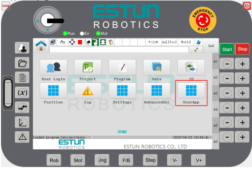
Figure 7-77 Click “Multi-station Reservation”
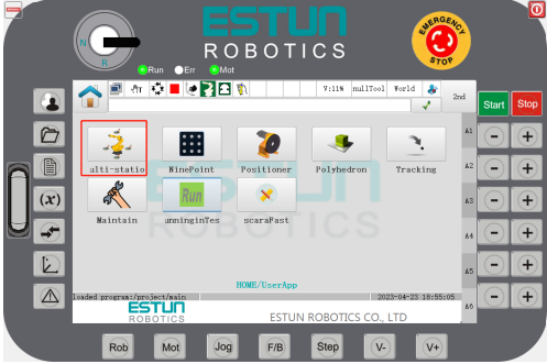
Step 2 After entering "Multi-station Reservation Settings", check "Multi-station Reservation Enable" and the "station" to be operated.
Figure 7-78 Checking the station
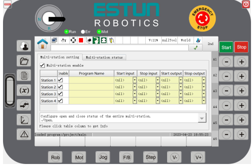
Step 3 Click the "program name" in the row where each "station" is located.
Figure 7-79 Click on the “Program Name”
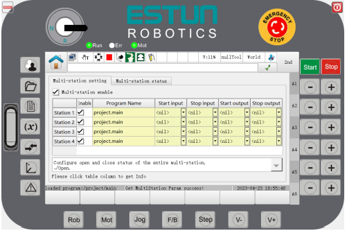
Step 4 Select the program you want to perform from the "Project List".
Figure 7-80 Selecting the program
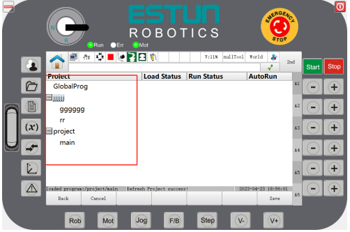 Click "Back" to return to the "Multi-station Reservation Setting" interface.
Click "Clear" to reset the "Preset Program" of the "Station".
Click "Select" to preset the currently selected "Program" to this "Station", and return to the "Multi-station Reservation Setting" interface.
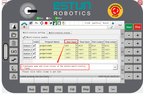
Step 5 Assign the "Start Input", "Stop Input", "Status Output" and "Stop Output" signals to each "station" correctly.
Note: Repeated use of the unified IO ports is not allowed.
Figure 7-81 Selection of IO signals
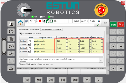
User can click each cell in the table header listed on the interface to view the “Help” information.
Figure 7-82 View the “Help” information
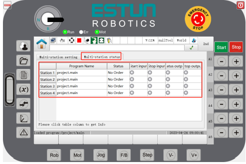
Step 6 Click "Multi-station Reservation Status" to view the status of each "Station" as well as its IO signal status.
Figure 7-83 View the status
Note
⚫ After the parameters of the Multi-station Reservation are properly set, you can perform the multi-station reservation operation after switching the system to Playback mode.
⚫ When a program is not executed and the reservation is successfully made, but you then want to cancel the current reservation, just cancel the reservation by inputting signal to the start unit.
----END
7.22 Positioner function
Function overview
With the positioner function, the workpiece can be moved to a suitable position for welding upon the rotation and flip of the worktable. It also makes collaborative motion with the robot so as to improve the production efficiency and welding quality.
Up to 6 positioners can be configured. 1-axis rotary positioners and 2-axis rotary positioners are supported.
Note: In the screenshots of this chapter, the axis name "Ex" is equivalent to "PEx".
Calibration of positioner coordinate system
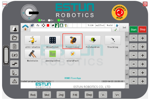
Step 1 Click "Positioner" in the "User Application" plug-ins on the Home interface, as shown in Figure 7-84.
Figure 7-84 Selecting the positioner
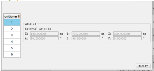
Step 2: Select the "Positioner ID" to be set, for example, selecting positioner ID = "1".
Figure 7-85 Selecting the positioner ID to be set
Step 3 Click "Modify" to set the coordinate system of positioner ID=1.
The positioner coordinate system can be determined by inputting or by calibration.
Figure 7-86 Setting or teaching the positioner ID=1
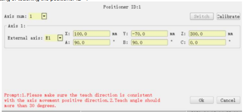
Step 4 Set the "Number of Axis" as needed.
It is defaulted as "1", indicating 1 additional axis. User only needs to calibrate one additional axis.
It indicates 2 additional axes if set it to “2”. User needs to calibrate the 2 additional axes.
When the number of axes is set to "2", select the additional axis to be calibrated by clicking "Switch Axis".

Step 5 Select "Additional Axis", and then click "Calibrate".
Figure 7-87 Select additional axis and prepare for calibration
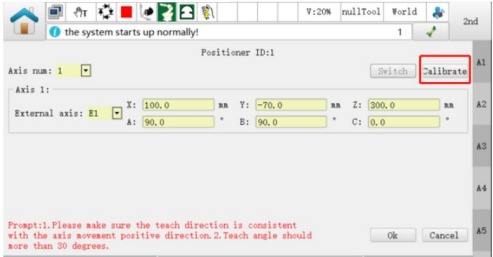

Step 6 Select the model of the positioner, e.g. "Model 1".
Figure 7-88 Select the model of the positioner
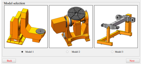
Note
For the model 3 corresponding to the "3-axis positioner", it can be configured as two two-axis positioner.
Step 7 Click "Next" to teach the positioner at three points.
[How to calibrate]
1. Install a point device or find a characteristic point prior to calibration as a marked position.
2. Move the robot TCP to such position, and then click "Teach".
3. Click "Next" and continue to rotate the positioner axis to an angle (recommended greater than 30°), move the robot TCP to the marked position, and then click "Teach".
4. Click "Next", and after rotating the positioner axis to the angle (recommended greater than 30°) for the second time, move the robot TCP to the marked position, and then click "Teach".
5. Click "Next", and the calibration "result" will appear.
Step 8 Click "OK" after they are confirmed to be correct.
Note
When calibrating the "2-axis coordinate system", make sure that the additional axis corresponded to the 1- axis of the positioner is at the zero position. Then, click "Switch Axis", and calibrate the 2-axis coordinate system with the same method.
Step 9 After returning to the positioner coordinate system interface, click "OK", and the positioner ID=1 coordinate system is successfully calibrated.
----END
Use of positioner coordinate system
Before the positioner coordinate system is used, it is necessary to create a POSITIONER variable, and specify the parameter index as the correct positioner ID. This can be done in two ways:
Use the command "SetPositioner" directly, which indicates to switch the system coordinate system to the positioner coordinate system.
When following motion commands are used, set the "Coordinate System Parameter" to the specified Positioner variable.
MovL, MovC, MovLRel, MovLSearch, MovH, MovLW, MovCW.
Example
The left and right sides of the robot are provided with a positioner each. The robot first performs synchronous motion with the U-shaped positioner on the left (variable POSITIONER1 has been set), and then with the L-shaped positioner on the right (variable POSITIONER0 has been set). The structure of command is shown in Figure 7-89.
Figure 7-89 Operation of positioner
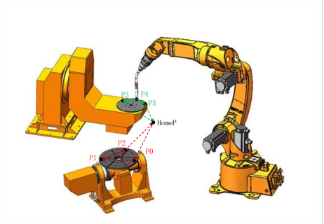
The executing commands are detailed as follows.
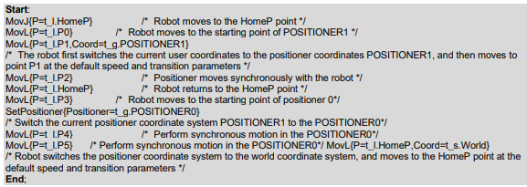
7.23 Execution in reverse
Function overview
This function is introduced if sometimes it needs to return according to the original track to avoid collisions, etc. when the program executes the complex motion commands. In the above situation, execution in reverse is required, so as to return to the original track.
In the reverse mode, the motion commands that are allowed for execution in reverse will perform such operation, and alarms will be given for the motions or other commands that are not allowed. Other commands that do not affect the return of the original track will be skipped and not executed.
Way of use
In manual mode, press the "F/B" key to enter the Execution in Reverse mode, and press the "F/B" key again to return to the positive sequence mode.

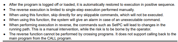
The executable and skip-able commands during reverse execution are shown in Table 7-10. Any commands not listed are unexecutable.
Note
The END line or the commented command line as well as the comment line or Label command line are all skippable by default.
Table 7-10 Commands of execution in reverse
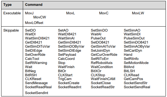
7.24 Servo parameter self-tuning function
Function overview
The servo parameter self-tuning function is designed to improve jittering during various robot applications during low-speed running. It can also reduce the large position error caused by jittering. By setting corresponding parameters, the best effect can be achieved in various speed ranges.
The servo parameter self-tuning function is mainly used to improve the low-speed shaking phenomenon of the robot within a certain speed range. To enable this function, use the command "AutoGainEnable()" and set the following parameters: gain ratio threshold and speed range threshold.
The gain ratio threshold (LsScale) is set for each joint axis, with a range of [100, 1000], in %.
The speed range threshold (LsThresh) is set for each motor axis, with a range of [10, 1000], in r/min.
The servo parameter self-tuning process depends on servo parameter Pn104. If Pn104 is modified, there may be slight differences in the effect when using the same parameter (gain ratio threshold) before and after the modification.
To disable the servo parameter self-tuning function, use the command "AutoGainDisable()".

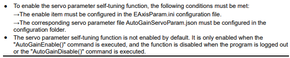
Application Example
When the program executes the "Servo parameter self-tuning function" start command, the function is enabled. Once enabled, the controller will automatically adjust the corresponding servo parameters. If the set command parameter value exceeds the maximum limit, the controller will issue an alarm.
Example of teaching program:

7.25 Cross-wrist singularity function
Function overview
The Cross-wrist Singularity Function enables the robot to traverse through the wrist singularity point (when J5=0, wrist singularity occurs) along the taught path, thereby improving the robot's motion space. However, the cross-wrist singularity function cannot guarantee the orientation of the robot during path motion.
Cross-wrist singularity function can be turned ON or OFF via command.
The SetSingularPass ("string") is used to set the switch of the cross-wrist singularity function.
Cross-wrist singularity function.The string can be "OPEN" or "CLOSE". When "OPEN" is selected, the cross-wrist singularity function is turned on, and when "CLOSE" is selected, the function is turned OFF.
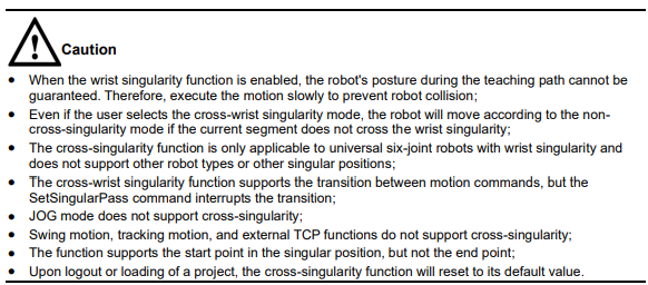
Application Example
When the command for cross-singularity function is executed, the function is turned ON. If the crosssingularity OFF command is not executed, the function remains ON.
Example of teaching program:

