
3. Commands
3.1 Motion commands
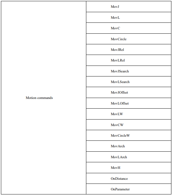
The list of motion commands:
MovJ
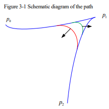
It indicates that each joint of the robot performs point-to-point motion. The end trajectory of the robot is an irregular curve, and the IO command can be operated when the command operates to an end. Description of the command parameters:
MovJ P [V] [B] [C] [Tool][Coord] [PayLoad][DO]
(Note: parameters indicated with [] are optional)
P: Target position (Target Pos)
Data type: APOS or CPOS variable
Meaning: The target point position in the coordinate system.
[V]: Target speed (Velo)
Data type: SPEED variable
Meaning: To specify the speed at which the robot executes MovJ. It includes the translational speed of the robots end effector, rotational speed, and speed of external axes, among others. The per component of the
SPEED variable is valid. If there are external axes present, the exj_l and exj_r components in the SPEED variable are valid as well.
Note: This parameter is optional and defaults to V4000.
[B]: Transition type (BlendType)
Data type: enum (FINE/RELATIVE/DEFAULT)
Meaning: The way of transition when the robot approaches the endpoint.
− FINE: No transition.
− RELATIVE: Relative transition.
− ABSOLUTE: Absolute transition.
− DEFAULT: Default type.
Note: This parameter is optional and defaults to FINE.
[C]: Transition Value (BlendValue)
Data type: ZONE variable
Meaning: The transition value when the robot approaches the endpoint.
Note: This parameter is optional and defaults to C100.
[Tool]: Tool Parameters (Tool)
Data type: TOOL variable
Meaning: The tool parameters used when the robot executes the path.
Note: This parameter is optional and defaults to to the current Tool Parameters set in the system.
[Coord]: Coordinate System Parameters (Coord)
Data type: USERCOOR variable
Meaning: The user coordinate system used by the robot when executing the path.
Note: This parameter is optional and defaults to defaults to the current Coordinate System Parameters set in the system.
[PayLoad]: Workpiece load (PayLoad)
Data type: PAYLOAD variable
Meaning: The workpiece load parameter used by the robot when executing the path.
Note: This parameter is optional and to the current payload parameter set in the system.
[DO]: IO operation to be performed after motion done (Add Do)
Data type: string
Meaning: The IO operation that can be triggered after the robot completes the command:
− NULL: No operation.
− IO commands: Perform IO operations. Currently supported IO instructions include SetDo, SetAo,
SetSimDo, SetSimAo, PulseOut, PulseSimOut, SetDO8421, SetDIEdge and SetSimDIEdge.
Example 1:

Example 2:

Example 3:


Example 4:

MovL
MovL is the linear motion command, through which the TCP point of the robot can be moved linearly to the target position at the set speed. If the start and end postures of the motion differ, then during operation the posture will synchronously rotate to the ending posture along with the position. It is the same as MovJ. An additional IO operation can be performed when the command is executed. The parameter setting of MovL is similar to MovJ. The command parameters are described as below:
MovLP [V] [B] [C][Tool][Coord] [PayLoad][O] [DO]
(Note: parameters indicated with [] are optional)
P: Target Position (Target Pos)
Data type: APOS or CPOS variable
Meaning: The target point position in the coordinate system.
[V]: Target speed (Velo)
Data type: SPEED variable
To specify the speed at which the robot executes MovL. It includes the translational speed of the robots end effector, rotational speed, and speed of external axes, among others. In this case, the tcp and ori components in the SPEED variable are valid. If there are external axes present, the exj_l and exj_r components in the SPEED variable are valid as well.
Note: This parameter is optional and defaults to V4000.
[B]: Transition type (BlendType)
Data type: enum (FINE/RELATIVE/DEFAULT)
Meaning: The way of transition when the robot approaches the endpoint.
− FINE: No transition.
− RELATIVE: Relative transition.
− ABSOLUTE: Absolute transition.
− DEFAULT: The type of default.
Note: This parameter is optional and defaults to FINE.
[C]: Transition Value (BlendValue)
Data type: ZONE variable
Meaning: The transition value when the robot approaches the endpoint.
Note: This parameter is optional and defaults to C100.
[Tool]: Tool Parameters (Tool)
Data type: TOOL variable
Meaning: The tool parameters used when the robot executes the path.
Note: This parameter is optional and defaults to the Tool Parameters set in the current system.
[Coord]: Coordinate System Parameters (Coord)
Data type: USERCOOR or EXTTCP or POSITIONER variable
Meaning: The user coordinate system/external TCP coordinate system/POSITIONER coordinate system used by the robot when executing the path.
Note: This parameter is optional and defaults to the Coordinate System Parameters set in the current system.
[PayLoad]: Workpiece load (PayLoad)
Data type: PAYLOAD variable
Meaning: The workpiece load parameter used by the robot when executing the path.
Note: This parameter is optional and defaults to the payload parameters set in the current system.
O: Rate type (OverrideType)
Data type: enum (GOVRON/GOVROFF)
− GOVRON: This path segment is affected by the Global Speed Multiplier.
− GOVROFF: This path segment is not affected by the Global Speed Multiplier.
Meaning: To set whether the current command path is affected by the Global Speed Multiplier.
Note: This parameter is optional and defaults to GOVRON.
[DO]: IO operations to be executed after motion done (Add Do)
Data type: string
Meaning: The IO operations that can be triggered after the robot completes the command:
− NULL: No operation.
− IO commands: Executing IO operation. The IO commands currently available are SetDo,
SetAo, SetSimDo, SetSimAo, PulseOut, PulseSimOut, SetDO8421, SetDIEdge,
SetSimDIEdge.
MovC
Arc command refers to the full-circle motion made by the robot’s TCP point from the starting position to the target by passing through the middle position. If the start and end postures of the motion are different, the posture will rotate to the end posture synchronously with the position, but it may not necessarily pass through the middle position.
MovCA P[V] [B] [C][Tool][Coord] [PayLoad][O] [DO]
(Note: parameters indicated with [] are optional)
A: Middle position (AuxPos)
Data type: APOS or CPOS variable
Meaning: The auxiliary point position used to determine the size of the arc and its motion direction. The orientation of this point does not affect the final path execution.
P: Target position (Target Pos)
Data type: APOS or CPOS variable
Meaning: The target point position in the coordinate system.
[V]: Target speed (Velo)
Data type: SPEED variable
Meaning: To specify the speed at which the robot executes MovC. It includes the translational speed of the robots end effector, rotational speed, and speed of external axes, among others. In this case, the tcp and ori components in the SPEED variable are valid. If there are external axes present, the exj_l and exj_r components in the SPEED variable are valid as well.
Note: This parameter is optional and defaults to V4000.
[B]: Transition type (BlendType)
Data type: enum (FINE/RELATIVE/DEFAULT)
Meaning: The way of transition when the robot approaches the endpoint
− FINE: No transition.
− RELATIVE: Relative transition.
− ABSOLUTE: Absolute transition.
− DEFAULT: The type of default.
Note: This parameter is optional and defaults to FINE.
[C]: Transition Value (BlendValue)
Data type: ZONE variable
Meaning: The transition value when the robot approaches the endpoint.
Note: This parameter is optional and defaults to C100.
[Tool]: Tool Parameters (Tool)
Data type: TOOL variable
Meaning: The tool parameters used when the robot executes the path.
Note: This parameter is optional and defaults to the Tool Parameters set in the current system.
[Coord]: Coordinate System Parameters (Coord)
Data type: USERCOOR or EXTTCP or POSITIONER variable
Meaning: The user coordinate system/external TCP coordinate system/POSITIONER coordinate system used by the robot when executing the path.
Note: This parameter is optional and defaults to the Coordinate System Parameters set in the current system.
[PayLoad]: Workpiece load (PayLoad)
Data type: PAYLOAD variable
Meaning: The workpiece load parameter used by the robot when executing the path.
Note: This parameter is optional and defaults to the payload parameters set in the current system.
O: Rate type (OverrideType)
Data type: enum (GOVRON/GOVROFF)
− GOVRON: This path segment is affected by the Global Speed Multiplier.
− GOVROFF: This path segment is not affected by the Global Speed Multiplier.
Meaning: To set whether the current command path is affected by the Global Speed Multiplier.
Note: This parameter is optional and defaults to GOVRON.
[DO]: IO operations to be executed after motion done (Add Do)
Data type: string
Meaning: The IO operations that can be triggered after the robot completes the command:
− NULL: No operation.
− IO COMMANDS: EXECUTING IO OPERATION. THE IO COMMANDS CURRENTLY
AVAILABLE ARESetDo, SetAo, SetSimDo, SetSimAo, PulseOut, PulseSimOut, SetDO8421,
SetDIEdge, SetSimDIEdge.
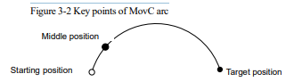
This command must satisfy:
To perform a full full-circle motion with the robot’s TCP end, two arc motion commands need to be executed.
MovCircle
MovCircle command means that the robot TCP point moves in a full circle from the start position to the start position through the auxiliary point 1 and auxiliary point 2 positions, with the pose remaining constant during the movement.
MovCircle A P[V] [B] [C][Tool] [Coord] [PayLoad] [O] [DO]
(Note: parameters indicated with [] are optional)
A: Middle position1 (AuxPos1)
Data type: APOS or CPOS variable
Meaning: The position 1 of the middle auxiliary point of the full circle, which is used to determine the size and movement direction of the arc. The pose of this point will not affect the final trajectory.
P: Middle position2 (AuxPos2)
Data type: APOS or CPOS variable
Meaning: The position 2 of the middle auxiliary point of the full circle, which is used to determine the size and movement direction of the arc. The pose of this point will not affect the final trajectory.
[V]: Target speed (Velo)
Data type: SPEED variable
Meaning: To specify the speed at which the robot executes MovCircle. It includes the translational speed of the robots end effector, rotational speed, and speed of external axes, among others. In this case, the tcp and ori components in the SPEED variable are valid. If there are external axes present, the exj_l and exj_r components in the SPEED variable are valid as well.
Note: This parameter is optional and defaults to V4000.
[B]: Transition type (BlendType)
Data type: enum (FINE/RELATIVE/DEFAULT)
Meaning: The way of transition when the robot approaches the endpoint.
− FINE: No transition.
− RELATIVE: Relative transition.
− ABSOLUTE: Absolute transition.
− DEFAULT: The type of default.
Note: This parameter is optional and defaults to FINE.
[C]: Transition Value (BlendValue)
Data type: ZONE variable
Meaning: The transition value when the robot approaches the endpoint.
Note: This parameter is optional and defaults to C100.
[Tool]: Tool Parameters (Tool)
Data type: TOOL variable
Meaning: The tool parameters used when the robot executes the path.
Note: This parameter is optional and defaults to the Tool Parameters set in the current system.
[Coord]: Coordinate System Parameters (Coord)
Data type: USERCOOR or EXTTCP or POSITIONER variable
Meaning: The user coordinate system/external TCP coordinate system/POSITIONER coordinate system used by the robot when executing the path.
Note: This parameter is optional and defaults to the Coordinate System Parameters set in the current system.
[PayLoad]: Workpiece load (PayLoad)
Data type: PAYLOAD variable
Meaning: The workpiece load parameter used by the robot when executing the path.
Note: This parameter is optional and defaults to the payload parameters set in the current system.
O: Rate type (OverrideType)
Data type: enum (GOVRON/GOVROFF)
− GOVRON: This path segment is affected by the Global Speed Multiplier.
− GOVROFF: This path segment is not affected by the Global Speed Multiplier.
Meaning: To set whether the current command path is affected by the Global Speed Multiplier.
Note: This parameter is optional and defaults to GOVRON.
[DO]: IO operations to be executed after motion done (Add Do)
Data type: string
Meaning: The IO operations that can be triggered after the robot completes the command:
− NULL: No operation.
− IO commands: executing io operation. The IO commands currently available are SetDo, SetAo,
SetSimDo, SetSimAo, PulseOut, PulseSimOut, SetDO8421, SetDIEdge, SetSimDIEdge
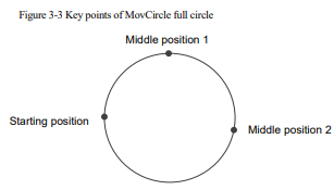
The command must adhere to the following specifications:
When teaching the points for the circular path, the "Middle position1" or "Middle position2" should not be too close to the starting point. The distance between "Middle position1" and "Middle position2" should also not be too close. Otherwise, it will trigger an alarm of "Calculating arc auxiliary information error";
The robots orientation remains constant during the full-circle motion;
During the full-circle motion, transitions are supported, and the command speed is not affected by the Global Multiplier;
If the starting point is in a singular position, cross-singularity mode must be enabled to execute the full-circle motion;
External TCP functionality supports full-circle motion;
Variable positioner and linear guides support full-circle motion, but it is crucial to ensure that the additional axis position remains unchanged during the full-circle motion;
Conveyor tracking functionality does not support full-circle motion;
MovJRel
The MovJ interpolation relative offset command. It works by taking the current robot position or the target position of the previous motion command as the starting point, and then perform the robot motion operation.
Unlike the commands such as MovJ, the target relative position value used by this command cannot be obtained through teaching. User needs to create a new joint relative position variable in the list of variables before, and then select it from the drop-down list. The parameters are defined as follows.
MovJRelP[V] [B] [C] [PayLoad][DO]
(Note: parameters indicated with [] are optional)
P: Target Relative Position (RelPos)
Data type: DAPOS variable
Meaning: The position increment the robot will move when executing this command.
[V]: Target speed (Velo)
Data type: SPEED variable
Meaning: To specify the speed at which the robot executes MovJRel. It includes the translational speed of the robots end effector, rotational speed, and speed of external axes, among others. In this case, the per component in the SPEED variable is valid. If there are external axes present, the exj_l and exj_r components in the SPEED variable are valid as well.
Note: This parameter is optional and defaults to V4000.
[B]: Transition type (BlendType)
Data type: enum (FINE/RELATIVE/DEFAULT)
Meaning: The way of transition when the robot approaches the endpoint.
− FINE: No transition.
− RELATIVE: Relative transition.
− ABSOLUTE: Absolute transition.
− DEFAULT: The type of default.
Note: This parameter is optional and defaults to FINE.
[C]: Transition Value (BlendValue)
Data type: ZONE variable
Meaning: The transition value when the robot approaches the endpoint.
Note: This parameter is optional and defaults to C100.
[PayLoad]: Workpiece load (PayLoad)
Data type: PAYLOAD variable
Meaning: The workpiece load parameter used by the robot when executing the path.
Note: This parameter is optional and defaults to the payload parameters set in the current system.
[DO]: IO operations to be executed after motion done (Add Do)
Data type: string
Meaning: The IO operations that can be triggered after the robot completes the command:
− NULL: No operation.
− IO COMMANDS: EXECUTING IO OPERATION. THE IO COMMANDS CURRENTLY
AVAILABLE ARESetDo, SetAo, SetSimDo, SetSimAo, PulseOut, PulseSimOut, SetDO8421,
SetDIEdge, SetSimDIEdge.
Example 1:

Example 2:

MovLRel
This command is used for relative linear motion. The command always starts from the current robot position or the target position of the previous motion command, and the robot moves relative to the specified displacement or orientation offset. Transition parameters can also be set, similar to MovJRel. The parameters are defined as shown in the following diagram:
MovLRelPT [V] [B] [C][PayLoad][O] [DO]
(Note: parameters indicated with [] are optional)
P: Target Relative Position (RelPos)
Data type: DCPOS variable
Meaning: The position increment the robot will move when executing this command.
T: Reference Coordinate System (RefSys)
Data type: enum (COORD/TOOL)
− COORD: Reference Coordinate System (RefSys).
− TOOL: Tool coordinate system.
Meaning: Reference coordinate system: Cartesian or Tool.
[V]: Target speed (Velo)
Data type: SPEED variable
Meaning: To specify the speed at which the robot executes MovLRel. It includes the translational speed of the robots end eff ector, rotational speed, and speed of external axes, among others. In this case, the tcp and ori components in the SPEED variable are valid. If there are external axes present, the exj_l and exj_r components in the SPEED variable are valid as well.
Note: This parameter is optional and defaults to V4000.
[B]: Transition type (BlendType)
Data type: enum (FINE/RELATIVE/DEFAULT)
Meaning: The way of transition when the robot approaches the endpoint.
− FINE: No transition.
− RELATIVE: Relative transition.
− ABSOLUTE: Absolute transition.
− DEFAULT: The type of default.
Note: This parameter is optional and defaults to FINE
[C]: Transition Value (BlendValue)
Data type: ZONE variable
Meaning: The transition value when the robot approaches the endpoint.
Note: This parameter is optional and defaults to C100.
[PayLoad]: Workpiece load (PayLoad)
Data type: PAYLOAD variable
Meaning: The workpiece load parameter used by the robot when executing the path.
Note: This parameter is optional and defaults to the payload parameters set in the current system.
O: Rate type (OverrideType)
Data type: enum (GOVRON/GOVROFF)
− GOVRON: This path segment is affected by the Global Speed Multiplier.
− GOVROFF: This path segment is not affected by the Global Speed Multiplier.
Meaning: To set whether the current command path is affected by the Global Speed Multiplier.
Note: This parameter is optional and defaults to GOVRON.
[DO]: IO operations to be executed after motion done (Add Do)
Data type: string
Meaning: The IO operations that can be triggered after the robot completes the command:
− NULL: No operation.
− IO COMMANDS: EXECUTING IO OPERATION. THE IO COMMANDS CURRENTLY
AVAILABLE ARESetDo, SetAo, SetSimDo, SetSimAo, PulseOut, PulseSimOut, SetDO8421,
SetDIEdge, SetSimDIEdge.
Example 1:

Example 2:

MovJSearch
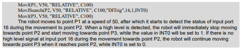
A search command. It performs IO detection or torque detection when executing the MovL command.
When the search condition is IO detection, if the indexed IO value reaches the Trigger value, the execution of the current command is stopped, and the next command is continued.
When the search condition is torque detection, if the indexed axis torque value reaches the Trigger value, the execution of the current command is stopped, and the next command is continued.
Please note that this command interrupts the transition.
The command parameters are defined as follows:
MovJSearchP [V] [B] [C][Tool][Coord] [PayLoad]Type Number Value [StopType]
[StopDecScale] R SearchP Goto [DO]
(Note: parameters indicated with [] are optional)
P: Target position (Target Pos)
Data type: APOS or CPOS variable
Meaning: The target point position in the coordinate system.
[V]: Target speed (Velo)
Data type: SPEED variable
Meaning: To specify the speed at which the robot executes MovJSearch. It includes the translational speed of the robots end effector, rotational speed, and speed of external axes, among others. In this case, the per component in the SPEED variable is valid. If there are external axes present, the exj_l and exj_r components in the SPEED variable are valid as well.
Note: This parameter is optional and defaults to V4000.
[B]: Transition type (BlendType)
Data type: enum (FINE/RELATIVE/DEFAULT)
Meaning: The way of transition when the robot approaches the endpoint.
− FINE: No transition.
− DEFAULT: The type of default.
Note: This parameter is optional and defaults to FINE.
[C]: Transition Value (BlendValue)
Data type: ZONE
Meaning: The transition value when the robot approaches the endpoint.
Note: This parameter is optional and defaults to C100.
[Tool]: Tool Parameters (Tool)
Data type: TOOL variable
Meaning: The tool parameters used when the robot executes the path.
Note: This parameter is optional and defaults to the Tool Parameters set in the current system.
[Coord]: Coordinate System Parameters (Coord)
Data type: USERCOOR variable
Meaning: The user coordinate system used by the robot when executing the path.
Note: This parameter is optional and defaults to the Coordinate System Parameters set in the current system.
[PayLoad]: Workpiece load (PayLoad)
Data type: PAYLOAD variable
Meaning: The workpiece load parameter used by the robot when executing the path.
Note: This parameter is optional and defaults to the payload parameters set in the current system.
Type: Type of detection (SearchType)
Data type: enum (DITrig/AITrig/SIMDITrig/SIMAITrig/TorqTrig)
− DITrig: Physical digital input trigger.
− AITrig: Physical analog input trigger.
− SIMDITrig: Virtual digital input trigger.
− SIMAITrig: Virtual analog input trigger.
− TorqTrig: Torque trigger.
Meaning: The type of operation to be monitored when the robot runs the path.
Number: Trigger index (SearchIndex)
Data type: int
Meaning: The Trigger index number to be monitored when the robot runs the path. For example, in the case of
DITrig trigger, this index number corresponds to the input port to be monitored. In the case of TorqTrig trigger, this index number corresponds to the axis to be monitored.
Value: Trigger value (SearchValue)
Data type: real
Meaning: The threshold value to be detected when the robot runs the path. For example, in the case of DITrig trigger, this value represents the high or low logic level to be detected on a specific input port. In the case of TorqTrig trigger, this value represents the rated torque permillage of a specific axis.
StopType: STOP type (StopType)
Data type: enum (HARDSTOP/SOFTSTOP/DEFAULT)
− HARDSTOP: Stops immediately;
− SOFTSTOP: Stop at reduced speed;
− DEFAULT: The type of default.
Meaning: The way to stop when a signal is detected.
Note: This parameter is optional and defaults to HARDSTOP.
StopDecScale: Decel Factor (StopDecScale)
Data type: real.
Meaning: The value is valid when "SOFTSTOP" is selected as "Stop Type". It is used to adjust the
Decel/Accel factor, the greater the value, the faster the deceleration.
R: Returned value (ResultV)
Data type: INT variable
Meaning: To return the status of the command execution upon completion. Returning 0 indicates that the condition triggering the command was not satisfied, returning 1 indicates that the condition triggering the command was satisfied, and returning 2 indicates that the condition triggering the command was satisfied at the motion starting point.
SearchP: Position of successful search (SearchPos)
Data type: APOS
Meaning: To return the coordinate position of the robot when the condition triggering the command is satisfied.
Note: This parameter is optional.
Goto: Label name to jump to in case of a search failure (LabelName)
Data type: label.
Meaning: The name of the label to which the program pointer will jump in case of a search failure.
This parameter is optional. If set to default, the system will not jump to the specified label for execution in case of a search failure.
[DO]: IO operations to be executed after motion done (Add Do)
Data type: string
Meaning: The IO operations that can be triggered after the robot completes the command:
− NULL: No operation.
− IO COMMANDS: EXECUTING IO OPERATION. THE IO COMMANDS CURRENTLY
AVAILABLE ARESetDo, SetAo, SetSimDo, SetSimAo, PulseOut, PulseSimOut, SetDO8421,
SetDIEdge, SetSimDIEdge.
Example 1:
MovLSearch
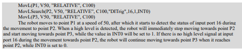
The Search Ccommand. It refers to IO detection or torque detection while executing this MovL command, which is similar to MovJSearch.
When the search condition is of IO detection and the value of the indexed IO reaches the trigger value, stop running this command and continue to execute the next command
When the search condition is of torque detection and the value of the index axis torque reaches the trigger value, stop running the command and continue to execute the next command.
Please note that this command will interrupt the transition.
The specific command parameters are defined as follows:
MovLSearchP [V] [B] [C][Tool][Coord] [PayLoad]Type Number Value [StopType] [StopDecScale] R SearchP Goto [DO]
(Note: parameters indicated with [] are optional)
P: Target position (Target Pos)
Data type: APOS or CPOS variable
Meaning: The target point position in the coordinate system.
[V]: Target speed (Velo)
Data type: SPEED variable
Meaning: To specify the speed at which the robot executes MovJSearch. It includes the translational speed of the robots end effector, rotational speed, and speed of external axes, among others. In this case, the tcp and ori components in the SPEED variable are valid. If there are external axes present, the exj_l and exj_r components in the SPEED variable are valid as well.
Note: This parameter is optional and defaults to V4000.
[B]: Transition type (BlendType)
Data type: enum (FINE/RELATIVE/DEFAULT)
Meaning: The way of transition when the robot approaches the endpoint.
− FINE: No transition.
− DEFAULT: The type of default.
Note: This parameter is optional and defaults to FINE.
[C]: Transition Value (BlendValue)
Data type: ZONE
Meaning: The transition value when the robot approaches the endpoint.
Note: This parameter is optional and defaults to C100.
[Tool]: Tool Parameters (Tool)
Data type: TOOL variable
Meaning: The tool parameters used when the robot executes the path.
Note: This parameter is optional and defaults to the Tool Parameters set in the current system.
[Coord]: Coordinate System Parameters (Coord)
Data type: USERCOOR or EXTTCP or POSITIONER variable
Meaning: The user coordinate system/external TCP coordinate system/POSITIONER coordinate system used by the robot when executing the path.
Note: This parameter is optional and defaults to the Coordinate System Parameters set in the current system.
[PayLoad]: Workpiece load (PayLoad)
Data type: PAYLOAD variable
Meaning: The workpiece load parameter used by the robot when executing the path.
Note: This parameter is optional and defaults to the payload parameters set in the current system.
Type: Type of detection (SearchType)
Data type: enum (DITrig/AITrig/SIMDITrig/SIMAITrig/TorqTrig)
− DITrig: Physical digital input trigger.
− AITrig: Physical analog input trigger.
− SIMDITrig: Virtual digital input trigger.
− SIMAITrig: Virtual analog input trigger.
− TorqTrig: Torque trigger.
Meaning: The type of operation to be monitored when the robot runs the path.
Number: Trigger index (SearchIndex)
Data type: int
Meaning: The Trigger index number to be monitored when the robot runs the path. For example, in the case of DITrig trigger, this index number corresponds to the input port to be monitored. In the case of TorqTrig trigger, this index number corresponds to the axis to be monitored.
Value: Trigger value (SearchValue)
Data type: real
Meaning: The threshold value to be detected when the robot runs the path. For example, in the case of DITrig trigger, this value represents the high or low logic level to be detected on a specific input port. In the case of TorqTrig trigger, this value represents the rated torque permillage of a specific axis.
StopType: STOP type (StopType)
Data type: enum (HARDSTOP/SOFTSTOP/DEFAULT)
− HARDSTOP: Stops immediately.
− SOFTSTOP: Stop at reduced speed.
− DEFAULT: The type of default.
Meaning: The way to stop when a signal is detected.
Note: This parameter is optional and defaults to HARDSTOP.
StopDecScale: Decel Factor (StopDecScale)
Data type: real.
Meaning: The value is valid when "SOFTSTOP" is selected as "Stop Type". It is used to adjust the Decel/Accel factor, the greater the value, the faster the deceleration.
R: Returned value (ResultV)
Data type: INT variable
Meaning: To return the execution status of this command. Returning 0 indicates that the condition triggering the command was not satisfied and the execution ended. Returning 1 indicates that the condition triggering the command was satisfied and the execution ended. Returning 2 indicates that the condition triggering the command was satisfied at the starting point of the motion and the execution ended.
SearchP: Position of successful search (SearchPos)
Data type: CPOS
Meaning: To return the coordinate position of the robot when the condition triggering the command is satisfied.
Note: This parameter is optional.
Goto: Label name to jump to in case of a search failure (LabelName)
Data type: label.
Meaning: The name of the label to which the program pointer will jump in case of a search failure.
This parameter is optional. If set to default, the system will not jump to the specified label for execution in case of a search failure.
[DO]: IO operations to be executed after motion done (Add Do)
Data type: string
Meaning: The IO operations that can be triggered after the robot completes the command:
− NULL: No operation.
− IO COMMANDS: EXECUTING IO OPERATION. THE IO COMMANDS CURRENTLY
AVAILABLE ARESetDo, SetAo, SetSimDo, SetSimAo, PulseOut, PulseSimOut, SetDO8421,
SetDIEdge, SetSimDIEdge.
Example 1:
MovJOffset
The Joint Space Offset command. It refers to a relative motion starting from a specified reference position, relative to a coordinate system or tool. The only difference from MovJRel is that this command specifies the starting point of the offset motion, which may not be the current position or the endpoint of the previous command. Other functionalities remain the same.
The specific command parameters are defined as follows:
MovJOffset RP TP T Tool Coord [V] [B] [C][PayLoad][O] [DO]
(Note: parameters indicated with [] are optional)
RP: Reference position (RefPos)
Data type: APOS or CPOS variable
Meaning: The position of the reference point in the coordinate system
TP: Target Relative Position (RelPos)
Data type: DCPOS or DAPOS variable
Meaning: The position increment relative to the reference position
T: Reference Coordinates (RefSys)
Data type: enum (COORD/TOOL)
− COORD: The user coordinate system.
− TOOL: The tool coordinate system.
Meaning: The reference coordinate system, either Cartesian or Tool.
Tool: Tool Parameters (Tool)
Data type: TOOL variable
Meaning: The tool parameters used when the robot executes the path.
Coord: Coordinate System Parameters (Coord)
Data type: USERCOOR variable
Meaning: The user coordinate system used by the robot when executing the path.
[V]: Target speed (Velo)
Data type: SPEED variable
Meaning: To specify the speed at which the robot performs the MovJOffset command. Please note that only the "per" component of the SPEED variable is valid in this context.
Note: This parameter is optional and defaults to V4000.
[B]: Transition type (BlendType)
Data type: enum (FINE/RELATIVE/DEFAULT)
Meaning: The way of transition when the robot approaches the endpoint.
− FINE: No transition.
− RELATIVE: Relative transition.
− ABSOLUTE: Absolute transition.
− DEFAULT: The type of default.
Note: This parameter is optional and defaults to FINE.
[C]: Transition Value (BlendValue)
Data type: ZONE
Meaning: The transition value when the robot approaches the endpoint.
Note: This parameter is optional and defaults to C100.
[PayLoad]: Workpiece load (PayLoad)
Data type: PAYLOAD variable
Meaning: The workpiece load parameter used by the robot when executing the path.
Note: This parameter is optional and defaults to the payload parameters set in the current system.
[DO]: IO operations to be executed after motion done (Add Do)
Data type: string
Meaning: The IO operations that can be triggered after the robot completes the command:
− NULL: No operation.
− IO COMMANDS: EXECUTING IO OPERATION. THE IO COMMANDS CURRENTLY AVAILABLE ARESetDo, SetAo, SetSimDo, SetSimAo, PulseOut, PulseSimOut, SetDO8421, SetDIEdge, SetSimDIEdge.
Example 1:

MovLOffset
The Linear Offset command. Itspecifies a reference position as the starting point and performs a relative offset motion with respect to the coordinate system or tool. The key difference from MovLRel is that this command explicitly specifies the starting point for the offset motion, which may not necessarily be the current position or the endpoint of the previous instruction, while other functionalities remain the same.
The specific command parameters are defined as follows:
MovLOffset RPTP T Tool Coord [V] [B] [C][PayLoad][O] [DO]
(Note: parameters indicated with [] are optional)
RP: Reference position (RefPos)
Data type: APOS or CPOS variable
Meaning: The position of the reference point in the coordinate system
TP: Target Relative Position (RelPos)
Data type: DCPOS variable
Meaning: The position increment relative to the reference position
T: Reference coordinate system (RefSys)
Data type: enum (COORD/TOOL)
− COORD: The Cartesian coordinate system.
− TOOL: The tool coordinate system.
Meaning: Reference Coordinates: either Cartesian or Tool
Tool: Tool Parameters (Tool)
Data type: TOOL variable
Meaning: The tool parameters used when the robot executes the path.
Coord: Coordinate System Parameters (Coord)
Data type: USERCOOR variable
Meaning: The user coordinate system used by the robot when executing the path.
[V]: Target speed (Velo)
Data type: SPEED variable
Meaning: To specify the speed at which the robot executes MovLOffset. It includes the translational speed of the robots end effector, rotational speed, and speed of external axes, among others. In this case, the tcp and ori components in the SPEED variable are valid. If there are external axes present, the exj_l and exj_r components in the SPEED variable are valid as well.
Note: This parameter is optional and defaults to V4000.
[B]: Transition type (BlendType)
Data type: enum (FINE/RELATIVE/DEFAULT)
Meaning: The way of transition when the robot approaches the endpoint.
− FINE: No transition.
− RELATIVE: Relative transition.
− ABSOLUTE: Absolute transition.
− DEFAULT: The type of default.
Note: This parameter is optional and defaults to FINE.
[C]: Transition Value (BlendValue)
Data type: ZONE
Meaning: The transition value when the robot approaches the endpoint.
Note: This parameter is optional and defaults to C100.
[PayLoad]: Workpiece load (PayLoad)
Data type: PAYLOAD variable
Meaning: The workpiece load parameter used by the robot when executing the path.
Note: This parameter is optional and defaults to the payload parameters set in the current system.
O: Rate type (OverrideType)
Data type: enum (GOVRON/GOVROFF)
− GOVRON: This path segment is affected by the Global Speed Multiplier.
− GOVROFF: This path segment is not affected by the Global Speed Multiplier.
Meaning: To set whether the current command path is affected by the Global Speed Multiplier.
Note: This parameter is optional and defaults to GOVRON.
[DO]: IO operations to be executed after motion done (Add Do)
Data type: string
Meaning: The IO operations that can be triggered after the robot completes the command:
− NULL: No operation.
− IO COMMANDS: EXECUTING IO OPERATION. THE IO COMMANDS CURRENTLY
AVAILABLE ARESetDo, SetAo, SetSimDo, SetSimAo, PulseOut, PulseSimOut, SetDO8421,
SetDIEdge, SetSimDIEdge.
Example 1:

MovLW
The WEAVE Motion command. It refers to the weave motion performed along the arc direction by setting the weave frequency and weave mplitude.
The parameters for this command are defined as shown in the diagram:
MovLWP [V] [B] [C][Tool][Coord] [PayLoad]WEAVE [O] [DO]
(Note: parameters indicated with [] are optional)
P: Target position (Target Pos)
Data type: APOS or CPOS variable
Meaning: The target point position in the coordinate system.
[V]: Target speed (Velo)
Data type: SPEED variable
Meaning: To specify the speed at which the robot executes MovLW. It includes the translational speed of the robots end effector, rotational speed, and speed of external axes, among others. In this case, the tcp and ori components in the SPEED variable are valid. If there are external axes present, the exj_l and exj_r components in the SPEED variable are valid as well.
Note: This parameter is optional and defaults to V4000.
[B]: Transition type (BlendType)
Data type: enum (FINE/RELATIVE/DEFAULT)
Meaning: The way of transition when the robot approaches the endpoint.
− FINE: No transition.
− RELATIVE: Relative transition.
− ABSOLUTE: Absolute transition.
− DEFAULT: The type of default.
Note: This parameter is optional and defaults to FINE.
[C]: Transition Value (BlendValue)
Data type: ZONE
Meaning: The transition value when the robot approaches the endpoint.
Note: This parameter is optional and defaults to C100.
[Tool]: Tool Parameters (Tool)
Data type: TOOL variable
Meaning: The tool parameters used when the robot executes the path.
Note: This parameter is optional and defaults to the Tool Parameters set in the current system.
[Coord]: Coordinate System Parameters (Coord)
Data type: USERCOOR or POSITIONER variable
Meaning: The user coordinate system/positioner coordinate system used by the robot to execute the path.
Note: This parameter is optional and defaults to the Coordinate System Parameters set in the current system.
[PayLoad]: Workpiece load (PayLoad)
Data type: PAYLOAD variable
Meaning: The workpiece load parameter used by the robot when executing the path.
Note: This parameter is optional and defaults to the payload parameters set in the current system.
WEAVE: WEAVE variable (Weave Value)
Data type: WEAVE variable
Meaning: The parameter set for the robots weave motion, which includes the weave frequency, weave amplitude, dwell time, rotation, and other related parameters.
O: Rate type (OverrideType)
Data type: enum (GOVRON/GOVROFF)
− GOVRON: This path segment is affected by the Global Speed Multiplier.
− GOVROFF: This path segment is not affected by the Global Speed Multiplier.
Meaning: To set whether the current command path is affected by the Global Speed Multiplier.
Note: This parameter is optional and defaults to GOVRON.
[DO]: IO operations to be executed after motion done (Add Do)
Data type: string
Meaning: The IO operations that can be triggered after the robot completes the command:
− NULL: No operation.
− IO COMMANDS: EXECUTING IO OPERATION. THE IO COMMANDS CURRENTLY AVAILABLE ARESetDo, SetAo, SetSimDo, SetSimAo, PulseOut, PulseSimOut, SetDO8421, SetDIEdge, SetSimDIEdge.
MovCW
The Circular Weave command. It refers to the weave motion performed along the arc direction by setting the weave frequency and weave mplitude.
The parameters for this command are defined as shown in the diagram:
MovCW AP [V] [B] [C][Tool][Coord] [PayLoad]WEAVE [O] [DO]
(Note: parameters indicated with [] are optional)
A: Middle position (AuxPos)
Data type: APOS or CPOS variable
Meaning: The auxiliary point position used to determine the size of the arc and its motion direction. The orientation of this point does not affect the final path execution.
P: Target position (Target Pos)
Data type: APOS or CPOS variable
Meaning: The target point position in the coordinate system.
[V]: Target speed (Velo)
Data type: SPEED variable
Meaning: To specify the speed at which the robot executes MovCW. It includes the translational speed of the robots end effector, rotational speed, and speed of external axes, among others. In this case, the tcp and ori components in the SPEED variable are valid. If there are external axes present, the exj_l and exj_r components in the SPEED variable are valid as well.
Note: This parameter is optional and defaults to V4000.
[B]: Transition type (BlendType)
Data type: enum (FINE/RELATIVE/DEFAULT)
Meaning: The way of transition when the robot approaches the endpoint.
− FINE: No transition.
− RELATIVE: Relative transition.
− ABSOLUTE: Absolute transition.
− DEFAULT: The type of default.
Note: This parameter is optional and defaults to FINE.
[C]: Transition Value (BlendValue)
Data type: ZONE
Meaning: The transition value when the robot approaches the endpoint.
Note: This parameter is optional and defaults to C100.
[Tool]: Tool Parameters (Tool)
Data type: TOOL variable
Meaning: The tool parameters used when the robot executes the path.
Note: This parameter is optional and defaults to the Tool Parameters set in the current system.
[Coord]: Coordinate System Parameters (Coord)
Data type: USERCOOR or POSITIONER variable
Meaning: The user coordinate system/positioner coordinate system used by the robot to execute the path.
Note: This parameter is optional and defaults to the Coordinate System Parameters set in the current system.
[PayLoad]: Workpiece load (PayLoad)
Data type: PAYLOAD variable
Meaning: The workpiece load parameter used by the robot when executing the path.
Note: This parameter is optional and defaults to the payload parameters set in the current system.
WEAVE: WEAVE variable (Weave Value)
Data type: WEAVE variable
Meaning: The parameter set for the robots weave motion, which includes the weave frequency, weave amplitude, dwell time, rotation, and other related parameters.
O: Rate type (OverrideType)
Data type: enum (GOVRON/GOVROFF)
− GOVRON: This path segment is affected by the Global Speed Multiplier.
− GOVROFF: This path segment is not affected by the Global Speed Multiplier.
Meaning: To set whether the current command path is affected by the Global Speed Multiplier.
Note: This parameter is optional and defaults to GOVRON.
[DO]: IO operations to be executed after motion done (Add Do)
Data type: string
Meaning: The IO operations that can be triggered after the robot completes the command:
− NULL: No operation.
− IO COMMANDS: EXECUTING IO OPERATION. THE IO COMMANDS CURRENTLY
AVAILABLE ARESetDo, SetAo, SetSimDo, SetSimAo, PulseOut, PulseSimOut, SetDO8421,
SetDIEdge, SetSimDIEdge.
MovCircleW
The Circle Weave command. It allows the robot to maintain continuous weave motion during a full circle movement.
The supported weave motions currently include sinusoidal weave and triangular weave.
The parameters for this command are defined as shown in the diagram:
MovCircleW A P [V] [B] [C] [Tool] [Coord] [PayLoad] WEAVE [O] [DO]
(Note: parameters indicated with [] are optional)
A: Middle position1 (AuxPos1)
Data type: APOS or CPOS variable
Meaning: The middle position 1, which is used to determine the size and direction of the circular arc during a full-circle motion. The posture of this point does not affect the final path execution.
P: Middle position2 (AuxPos2)
Data type: APOS or CPOS variable
Meaning: The middle position 2, which is used to determine the size and direction of the circular arc during a full-circle motion. The posture of this point does not affect the final path execution.
[V]: Target speed (Velo)
Data type: SPEED variable
Meaning: To specify the speed at which the robot executes MovCircleW. It includes the translational speed of the robots end effector, rotational speed, and speed of external axes, among others. In this case, the tcp and ori components in the SPEED variable are valid. If there are external axes present, the exj_l and exj_r components in the SPEED variable are valid as well.
Note: This parameter is optional and defaults to V4000.
[B]: Transition type (BlendType)
Data type: enum (FINE/RELATIVE/DEFAULT)
Meaning: The way of transition when the robot approaches the endpoint.
− FINE: No transition.
− RELATIVE: Relative transition.
− ABSOLUTE: Absolute transition.
− DEFAULT: The type of default.
Note: This parameter is optional and defaults to FINE.
[C]: Transition Value (BlendValue)
Data type: ZONE
Meaning: The transition value when the robot approaches the endpoint.
Note: This parameter is optional and defaults to C100.
[Tool]: Tool Parameters (Tool)
Data type: TOOL variable
Meaning: The tool parameters used when the robot executes the path
Note: This parameter is optional and defaults to the Tool Parameters set in the current system.
[Coord]: Coordinate System Parameters (Coord)
Data type: USERCOOR or POSITIONER variable
Meaning: The user coordinate system/positioner coordinate system used by the robot to execute the path.
Note: This parameter is optional and defaults to the Coordinate System Parameters set in the current system.
[PayLoad]: Workpiece load (PayLoad)
Data type: PAYLOAD variable
Meaning: The workpiece load parameter used by the robot when executing the path.
Note: This parameter is optional and defaults to the payload parameters set in the current system.
WEAVE: WEAVE variable (Weave Value)
Data type: WEAVE variable
Meaning: The parameter set for the robots weave motion, which includes the weave frequency, weave amplitude, dwell time, rotation, and other related parameters.
O: Rate type (OverrideType)
Data type: enum (GOVRON/GOVROFF)
− GOVRON: This path segment is affected by the Global Speed Multiplier.
− GOVROFF: This path segment is not affected by the Global Speed Multiplier.
Meaning: To set whether the current command path is affected by the Global Speed Multiplier.
Note: This parameter is optional and defaults to GOVRON.
[DO]: IO operations to be executed after motion done (Add Do)
Data type: string
Meaning: The IO operations that can be triggered after the robot completes the command:
− NULL: No operation.
− IO COMMANDS: EXECUTING IO OPERATION. THE IO COMMANDS CURRENTLY AVAILABLE ARESetDo, SetAo, SetSimDo, SetSimAo, PulseOut, PulseSimOut, SetDO8421, SetDIEdge, SetSimDIEdge.
OnDistance
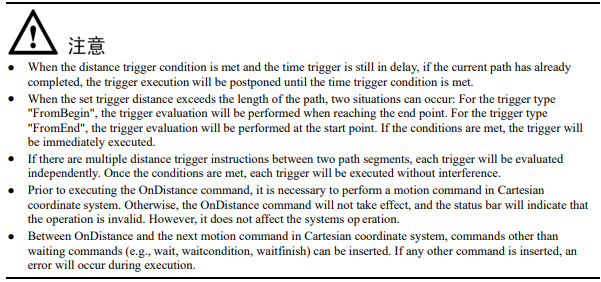
The Distance Trigger command. It allows the controller to perform certain actions, such as assigning values or setting IO, when the robot moves a specified distance from the start or end point of a linear or circular path, without interrupting the transition.
The parameter definitions for this command are as follows:
OnDistance TypeDistTimeMs DO
Type: Trigger type (Type)
Data type: enum (FromBegin/FromEnd)
− FromBegin: Trigger from the start point.
− FromEnd: Trigger from the end point.
Meaning: The method to detect the distance trigger. It determines whether the trigger distance is calculated from the start or end point
Dist: Trigger distance (TrigDis)
Data type: real or REAL variable
Meaning: The distance relative to the start or end point that triggers the action.
TimeMs: The distance relative to the start or end point that triggers the action.
Data type: int or INT variable
Meaning: The delay time after meeting the trigger condition before executing the action. This value can be negative, where a negative value indicates a forward delay trigger.
DO: IO operation to be executed after motion done (Do)
Data type: string
Meaning: To specify the command operation to be triggered when the robot meets the trigger condition. These operations can include assignment commands and IO commands.
When the trigger type is set to "FromBegin", the controller enters the trigger wait state after the robot moves the specified distance from the start point. After the delay trigger time, the related trigger operation is executed.
When the trigger type is set to "FromEnd", the controller enters the trigger wait state after the robot moves the specified distance from the end point. After the delay trigger time, the related trigger operation is executed.
Example 1: Execute the Do operation with a delay of 100ms when the distance from the start point to P2 on the trajectory from P1 to P2 is 200mm.

Example 2: Execute the Do operation with a delay of 100ms when the distance from the start point to P2 on the trajectory from P1 to P2 is 200mm.

OnParameter
The Distance Percentage Trigger command. It is used to trigger certain operations, such as assigning values or setting IO, at a specific location along the motion paths without interrupting the transitions. When the robot reaches the defined percentage of the path, the controller enters a trigger waiting state. After a specified delay time, it proceeds to execute the associated trigger operations.
The parameter definitions for this command are as follows:
OnParameter Percence TimeMsDO
Perence: Trigger Type (Type)
Data type: int
Meaning: The percentage of the path where the trigger should occur
TimeMs: Trigger Time (TrigTime)
Data type: int or INT variable
Meaning: The delay time after satisfying the trigger condition. Negative values indicate a delay towards the beginning of the motion.
DO: IO operations to be executed after motion done (Do)
Data type: string
Meaning: The command operations that can be triggered when the robot satisfies the trigger condition, including assignment instructions and IO commands.
Example:

MovArch
The joint arc motion comand for SCARA robot models. It is executed in the form of MovJ to complete a path. The entire motion process involves the following steps: first, the robot lifts to a height of h1 at the current point, then moves to a height of h2 relative to the target point, and finally descends by a height of h2 to reach the target point, thereby accomplishing an arc motion. Similar to regular motion instructions, additional I/O operations can be performed upon completion of this command. The Target Speed of this command is specified as a percentage.
Note: This command is currently only applicable to SCARA robot models and does not support six axis robots.
The command parameters are described as below:
MovArchP [V] [B] [C][Tool][Coord] [PayLoad]H H2Z [DO]
(Note: parameters indicated with [] are optional)
P: Target position (Target Pos)
Data type: APOS or CPOS variable
Meaning: The target point position in the coordinate system.
[V]: Target speed (Velo)
Data type: SPEED variable
Meaning: To specify the speed at which the robot executes MovL. It includes the translational speed of the robots end effector, rotational speed, and speed of external axes, among others. In this case, the per component in the SPEED variable is valid. If there are external axes present, the exj_l and exj_r components in the SPEED variable are valid as well.
Note: This parameter is optional and defaults to V4000.
[B]: Transition type (BlendType)
Data type: enum (FINE/RELATIVE/DEFAULT)
Meaning: The way of transition when the robot approaches the endpoint.
− FINE: No transition.
− RELATIVE: Relative transition.
− ABSOLUTE: Absolute transition.
− DEFAULT: The type of default.
Note: This parameter is optional and defaults to FINE.
[C]: Transition Value (BlendValue)
Data type: ZONE
Meaning: When the robot approaches the endpoint, the Transition Value (a ZONE-type variable) is utilized. In this context, the "per" parameter corresponds to the relative transition type, while the "dis" parameter corresponds to the absolute transition type.
Note: This parameter is optional and defaults to C100.
[Tool]: Tool Parameters (Tool)
Data type: TOOL variable
Meaning: The tool parameters used when the robot executes the path.
Note: This parameter is optional and defaults to the Tool Parameters set in the current system.
[Coord]: Coordinate System Parameters (Coord)
Data type: USERCOOR variable
Meaning: The user coordinate system used by the robot when executing the path.
Note: This parameter is optional and defaults to the Coordinate System Parameters set in the current system.
[PayLoad]: Workpiece load (PayLoad)
Data type: PAYLOAD variable
Meaning: The workpiece load parameter used by the robot when executing the path.
Note: This parameter is optional and defaults to the payload parameters set in the current system.
H: Lifting height (Lift High)
Data type: real
Meaning: The height that the robot needs to lift during the arc motion.
H2: Drop height Drop High)
Data type: real
Meaning: The height that the robot needs to descend during the arc motion.
Z: CornerValue
Data type: ZONE
Meaning: The corner value that the robot follows during the arc motion.
[DO]: IO operations to be executed after motion done (Add Do)
Data type: string
Meaning: The IO operations that can be triggered after the robot completes the command:
− NULL: No operation.
− IO COMMANDS: EXECUTING IO OPERATION. THE IO COMMANDS CURRENTLY AVAILABLE ARESetDo, SetAo, SetSimDo, SetSimAo, PulseOut, PulseSimOut, SetDO8421, SetDIEdge, SetSimDIEdge.
Example:

MovLArch
The linear arch-shaped motion comand for SCARA robot models. It is executed in the form of MovL to complete the path. The motion process involves raising the robot to a height of h1 at the current point, then moving in a MovL manner to a height of h2 relative to the target point, and finally descending by a height of h2 to reach the target point, thereby accomplishing an arch-shaped motion. Similar to normal motion commands, additional I/O operations can be performed upon completion of this command. The target speed of this command is specified as a percentage.
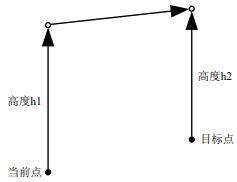
Note: This command is currently only applicable to SCARA robot models and is not supported for six axis robots.
The command parameters are described as below:
MovLArchP [V] [B] [C][Tool][Coord] [PayLoad]H H2Z [O] [DO]
(Note: parameters indicated with [] are optional)
P: Target position (Target Pos)
Data type: APOS or CPOS variable
Meaning: The target point position in the coordinate system.
[V]: Target speed (Velo)
Data type: SPEED variable
Meaning: To specify the speed at which the robot executes MovL. It includes the translational speed of the robots end effector, rotational speed, and speed of external axes, among others. In this case, the per component in the SPEED variable is valid. If there are external axes present, the exj_l and exj_r components in the SPEED variable are valid as well.
Note: This parameter is optional and defaults to V4000.
[B]: Transition type (BlendType)
Data type: enum (FINE/RELATIVE/DEFAULT)
Meaning: The way of transition when the robot approaches the endpoint.
− FINE: No transition.
− RELATIVE: Relative transition.
− ABSOLUTE: Absolute transition.
− DEFAULT: The type of default.
Note: This parameter is optional and defaults to FINE.
[C]: Transition Value (BlendValue)
Data type: ZONE
Meaning: The value of the transition when the robot approaches the end point (ZONE type variable) is determined by the "per" parameter for the relative Transition type, and the "dis" parameter for the absolute Transition type.
Note: This parameter is optional and defaults to C100.
[Tool]: Tool Parameters (Tool)
Data type: TOOL variable
Meaning: The tool parameters used when the robot executes the path.
Note: This parameter is optional and defaults to the Tool Parameters set in the current system.
[Coord]: Coordinate System Parameters (Coord)
Data type: USERCOOR variable
Meaning: The user coordinate system used by the robot when executing the path.
Note: This parameter is optional and defaults to the Coordinate System Parameters set in the current system.
[PayLoad]: Workpiece load (PayLoad)
Data type: PAYLOAD variable
Meaning: The workpiece load parameter used by the robot when executing the path.
Note: This parameter is optional and defaults to the payload parameters set in the current system.
H: Lifting height (Lift High)
Data type: real
Meaning: The height that the robot needs to lift during the arch-shaped motion.
H2: Drop height Drop High)
Data type: real
Meaning: The height that the robot needs to descend during the arch-shaped motion.
Z: Corner Value
Data type: ZONE
Meaning: The corner value that the robot follows during the arch-shaped motion.
O: Rate type (OverrideType)
Data type: enum (GOVRON/GOVROFF)
− GOVRON: This path segment is affected by the Global Speed Multiplier.
− GOVROFF: This path segment is not affected by the Global Speed Multiplier.
Meaning: To set whether the current command path is affected by the Global Speed Multiplier.
Note: This parameter is optional and defaults to GOVRON.
[DO]: IO operations to be executed after motion done (Add Do)
Data type: string
Meaning: The IO operations that can be triggered after the robot completes the command:
− NULL: No operation.
− IO COMMANDS: EXECUTING IO OPERATION. THE IO COMMANDS CURRENTLY AVAILABLE ARESetDo, SetAo, SetSimDo, SetSimAo, PulseOut, PulseSimOut, SetDO8421, SetDIEdge, SetSimDIEdge.
Example:

MovH
The helical motion command. It allows the robots TCP point to perform a helical motion to the target position. If the starting and ending orientations of the motion are different, the posture will rotate synchronously with the position during the motion to reach the final posture.
The command parameters are described as below:
MovH A P [V] [B] [C] [Tool] [Coord] [PayLoad] R S [DO]
(Note: parameters indicated with [] are optional)
A: Middle position (AuxPos)
Data type: APOS or CPOS variable
Meaning: The position of the helical middle auxiliary point. The auxiliary point is used to determine the helical plane and the helical direction (precession in clockwise and counterclockwise). The helical movement may not pass through the auxiliary point.
P: Target position (Target Pos)
Data type: APOS or CPOS variable
Meaning: The target point position in the coordinate system.
[V]: Target speed (Velo)
Data type: SPEED variable
Meaning: To specify the speed at which the robot executes the MovH command. The maximum path linear speed of the helical line is 0.25 times the maximum system speed.
[B]: Transition type (BlendType)
Note: MovH does not support transitions.
[C]: Transition Value (BlendValue)
Note: This parameter does not have any effect.
[Tool]: Tool Parameters (Tool)
Data type: TOOL variable
Meaning: The tool parameters used when the robot executes the path.
Note: This parameter is optional and defaults to the Tool Parameters set in the current system.
[Coord]: Coordinate System Parameters (Coord)
Data type: USERCOOR variable
Meaning: The user coordinate system used by the robot when executing the path.
Note: This parameter is optional and defaults to the Coordinate System Parameters set in the current system.
[PayLoad]: Workpiece load (PayLoad)
Data type: PAYLOAD variable
Meaning: The workpiece load parameter used by the robot when executing the path.
Note: This parameter is optional and defaults to the payload parameters set in the current system.
R: Radius)
Data type: real
Meaning: The radius of the helical line during the helical motion, in millimeters (mm).
S: Stepping distance
Data type: real
Meaning: The distance moved in the direction from the starting point to the ending point after completing one revolution of the helical rotation, in millimeters (mm).
[DO]: IO operations to be executed after motion done (Add Do)
Data type: string
Meaning: The IO operations that can be triggered after the robot completes the command:
− NULL: No operation.
− IO COMMANDS: EXECUTING IO OPERATION. THE IO COMMANDS CURRENTLY AVAILABLE ARESetDo, SetAo, SetSimDo, SetSimAo, PulseOut, PulseSimOut, SetDO8421, SetSimDO8421, SetDIEdge, SetSimDIEdge.
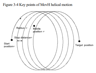
For Helical motion, the transition and WaitFinish are not supported.
Example:

3.2 Control commands
The list of control commands:
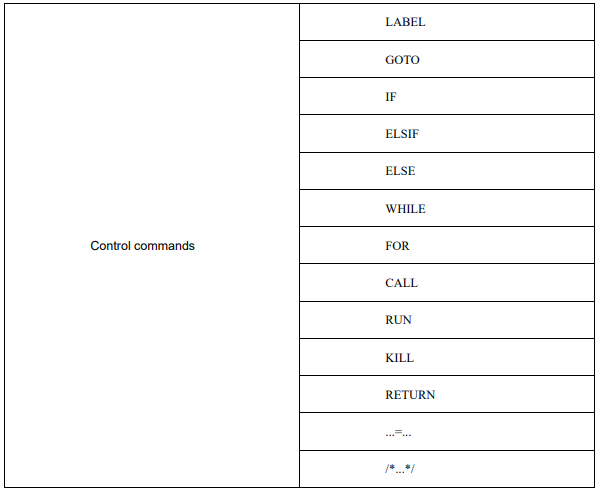
LABEL
Label command is used to define the GOTO jump target.
Example:

GOTO
GOTO command is used to jump to different parts of the program. The jump target is defined by the LABEL. It is not allowed to jump into the WHILE loop program block or the IF program block from outside.
Example:

IF
IF command is used for jump control of the conditional judgment expression. When the result of the conditional judgment expression is TRUE, the program executes the block content under IF. Every IF command must be followed by the keyword ENDIF to mark the end of the conditional statement block.
Example:

ELSIF
ELSIF relies upon the IF command. It follows closely the IF command block. When the IF logic is not established, the ELSIF logic judgment is performed.
The way to set the ELSIF expression is the same as that of the IF expression.

ELSE
The ELSE command is used in conjunction with the IF command to specify the statements to be executed when the condition of the IF statement is not satisfied.
Example:

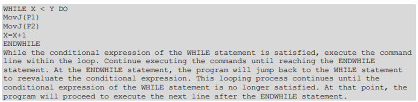
WHILE
WHILE command executes sub-statements in loops when the conditions are met. The loop control for this command must be terminated using the keyword ENDWHILE.
Example:
FOR
The FOR command is used to loop and execute a substatement while a condition is satisfied. This command must be terminated using the keyword ENDFOR as the loop control end. The FOR command consists of three segments separated by commas and has the following format:
FOR INT0.value = 0, INT0.value < 10, INT0.value = INT0.value + 1 DO
…
ENDFOR
The first segment of characters initializes the assignment. The second segment of characters is the loop condition. If the condition is satisfied, the content within the FOR loop is executed. If the condition is not satisfied, the program exits the FOR loop. The third segment consists of periodic execution statements that are executed once at the end of each iteration of the FOR loop
Example:

CALL
The CALL program command. The current program jumps to another subroutine in the same project, which then jumps back to the current program after execution.
For example, CALL B in program A, CALL C in B, CALL D in C, and CALL E in D
Example:

RUN
The program parallel running command. It enables the robot to run other programs while running the current program (programs must be in the same project), which means a new thread will be started to execute the other program while the current program continues to run normally.
Note: The current system supports running up to eight concurrent programs (excluding the main running program), and the RUN programs should not include motion-related commands.
Example:

KILL
To stop the commands running in parallel. This command is used to terminate programs launched by the RUN command.
Example:

RETURN
The Return command. After executing this command, the program will jump to the end of the program, to effectively terminate the current program.
Example:

...=...
Establish an expression to assign a value to a variable.
Example:

/*…*/
COMMENT command, to add definitions or remarks to the program.
This command will not affect the operation of the program, but only for reading and understanding the program.
Example:

3.3 WAIT commands