1. Preparations
1.1 Safety
1.1.1 For your safety
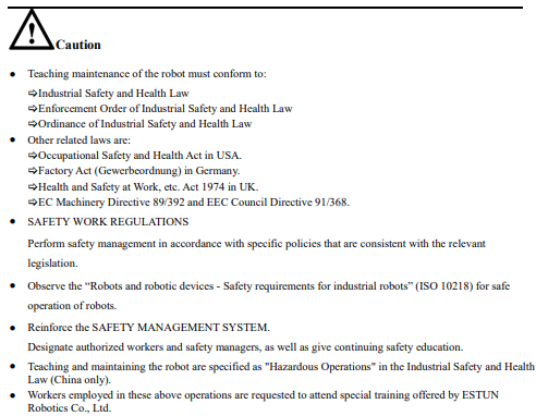
Robots generally have requirements which are different from other manufacturing equipment, such as larger working envelopes, high-speed operation, rapid arm movements, etc., which can pose safety hazards. Read and understand the instruction manuals and related documents, and observe all precautions in order to avoid the risk of injury to personnel and damage to equipment. It is the user's responsibility to ensure that their safe operating environment complies with and observes local and national safety-related laws, regulations and ordinances.
1.1.2 Specialized training

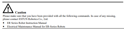
1.1.3 List of instruction manuals of robots
1.1.4 Safety precautions for operators
The maximum range of motion of the robot is potentially dangerous. All the involved workers (safety managers, installers, operators, and maintenance workers) must always be safety oriented to guarantee the safety of all workers.
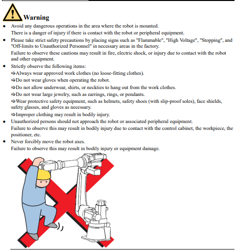
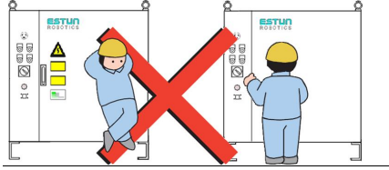
⚫ Never lean on the control cabinet, and avoid inadvertently pushing buttons.
Failure to observe this may result in bodily injury or damage by unexpected movement of the robot.
1.1.5 Robot safety precautions
Mounting and wiring safety
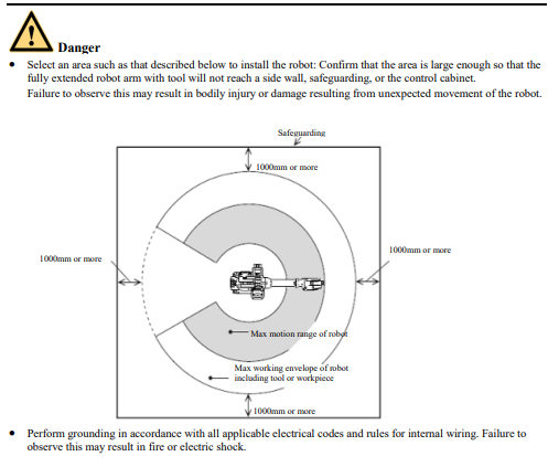
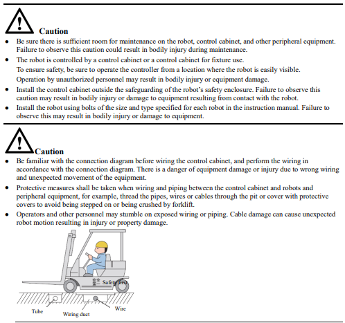
When installing and wiring, please check the detailed information from the ER series robot instruction manual. During the mounting preparation and mounting process, the following matters should be observed to ensure the safety of the mounting process.
Work area safety
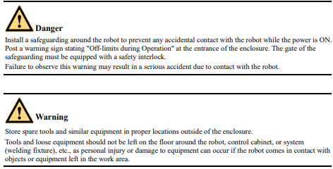
Carelessness contributes to serious accidents in the work area. To ensure safety, enforce the following precautions:
Operation safety
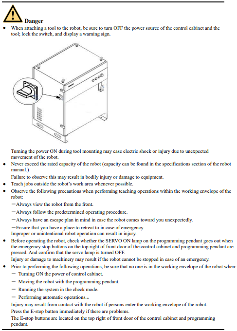

1.1.6 Precautions for moving and transferring the robot
When moving or transferring the robot, observe the following safety precautions:
1.1.7 Precautions for robot disposal

1.2Product Confirmation
1.2.1 Contents confirmation
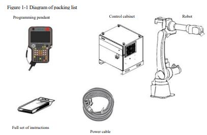
Confirm the contents of the delivery when the product arrives. Standard delivery includes the following five items: (information for the content of optional goods is given separately).
⚫ Robot
⚫ Control cabinet
⚫ Programming pendant
⚫ Power sourcesource cable (between robot and control cabinet)
⚫ Full set of instructions
1.2.2 Order number confirmation
Confirm whether the order number pasted on the robot and control cabinet match.
1.3Mounting
1.3.1 Handling method
Using a crane to transport the control cabinet
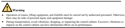
Prior to lifting the control cabinet, the following checks should be conducted:
1. Verify the weight of the control cabinet and employ lifting equipment with a load capacity exceeding the weight of the control cabinet.
2. Before lifting, secure the eyebolts and ensure they are fastened securely.
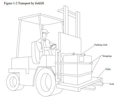
Using a forklift to transport the control cabinet
When using a forklift to transport the control cabinet, adhere to the following precautions:
1. Ensure a safe working environment to facilitate the secure transportation of the control cabinet to the mounting site.
2. Notify personnel working in the vicinity of the forklift route, making them aware that the control cabinet is being moved.
3. Prevent any shifting or tilting of the control cabinet during transportation.
4. Whenever possible, maintain a lowered height position while transporting the control cabinet.
5. Avoid vibrations, dropping, or impacting the control cabinet during transportation.
1.3.2 Mounting site and environment
The mounting site for the control cabinet must meet the following conditions:
⚫ During operation, the ambient temperature should be within 0 to 45°C (32 to 113°F); during transportation and maintenance, it should be within -10 to 60°C (14 to 140°F).
⚫ It should be in an environment with relatively low humidity and no condensation, maintaining a relative humidity of 10% to 90%.
⚫ The location should be relatively free from dust, powder, oil fumes, and water.
⚫ No flammable substances, corrosive liquids, or gases should be present in the operating area.
⚫ The site should experience minimal vibration or impact energy (vibration below 0.5G).
⚫ There should be no significant sources of electrical noise nearby (e.g. gas shielded welding TIG equipment).
⚫ There should be no potential hazards of collision with moving equipment (such as forklifts).
1.3.3 Mounting location
⚫ The control cabinet should be mounted outside the range of robot movement (outside the safety fence).
⚫ The control cabinet should be mounted in a position where the robot's actions can be clearly observed.
⚫ The control cabinet should be mounted in a position that facilitates easy access to open the door for inspection.
⚫ The control cabinet should be positioned at a minimum distance of 500 mm from the wall to ensure unobstructed maintenance access.
1.4 Introduction to the EWAS Arc Welding Teach Pendant
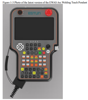
The new version of EWAS Arc Welding Teach Pendant is shown in figure below.
1.4.1 Key function
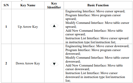
The keypad area of the new version of EWAS Arc Welding Teach Pendant comprises a total of 60 buttons. The specific functions of these 60 buttons are described as follows.
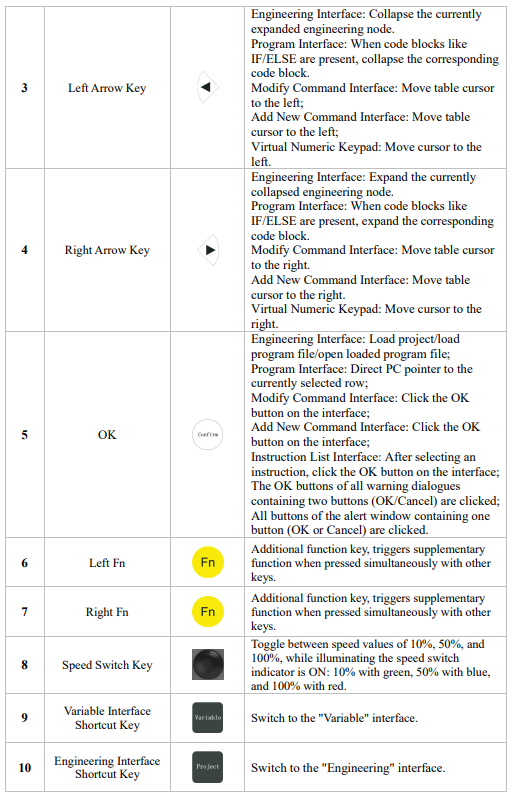
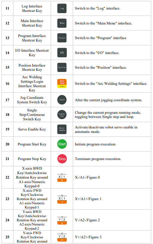
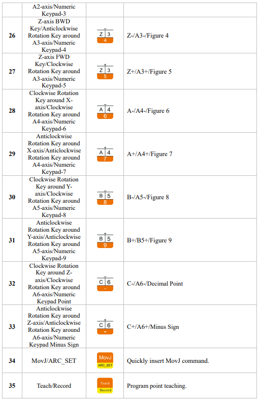
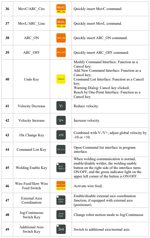
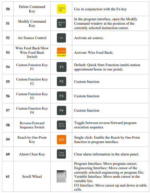
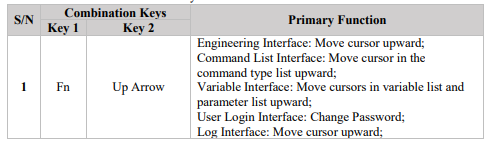
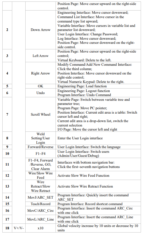
Here is the combination shortcut key function table:
1.4.2 Introduction to mode switches
Rotate the knob to switch between the three modes. Three modes are available for system running:
Teach Mode
You can do followings under teach mode:
⚫ Edit and teach the programs
⚫ Revise the program that have already been logged in
⚫ Set program files and parameters.
Playback Mode
You can perform following operation under Playback Mode:
⚫ Playback of teaching program
⚫ Setting, modification or deletion of program files.
Remote Mode
⚫ System may call out the programs stored in the memory at any time for editing and execution.
⚫ The program to be edited is called "Editor Program", which is the program displayed when the program content is displayed in the teaching mode.
⚫ The program to be executed is called "Executive Program", which is the program displayed when the program content is displayed in Playback mode.
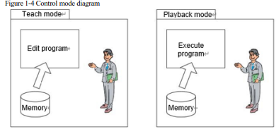
When switching the motion mode on the programming pendant, there will be no conversion between the editing program and the executive program. To run an editing program in Playback mode, you need to change the mode to Playback mode, and then read the program.
1.4.4 Servo enable switch
During teaching and jog operation, it's necessary to press the servo enable switch to activate the servo drive (energize). This switch has its first contact point in the pressed position for enabling the
signal, and when fully pressed, it releases the enabling signal. This switch is located at the righthand grip position of the teach pendant, functioning to establish or interrupt the enabling signal.
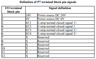
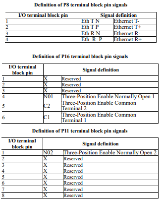
1.4.5 Signal definition of internal wiring terminal of programming pendant
Definition of I/O terminal block pin signals
1.4.6 Programming pendant cables
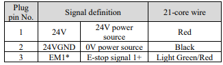
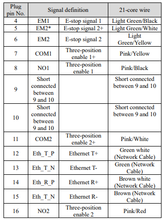
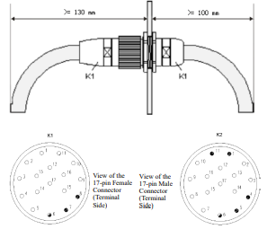
Definition of aviation plug interface signal
Connection between cable and control cabinet
Figure 1-5 The pin signal definitions for K1 and K2 are the same as the signal definitions provided in the Aviation Plug Interface Signal Definitions for the corresponding pins
1.5Basic Use
This section provides fundamental usage guidelines for the new EWAS arc welding teach pendant, including proper wiring, standardized procedures for startup, shutdown, correct rebooting, and system upgrades.
1.5.1 Wiring
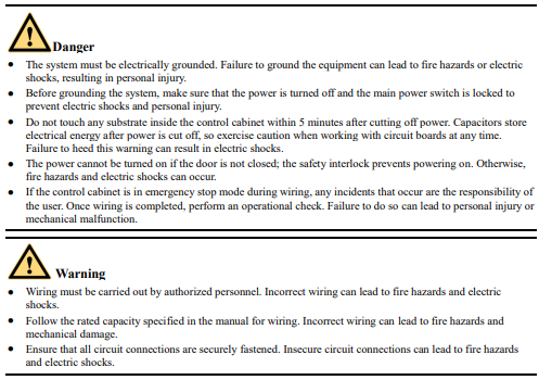
Precautions for cable connection
⚫ Cables connecting the control cabinet and peripheral devices are low-voltage cables. Signal cables from the control cabinet should be kept at a distance from the main power source circuit. High-voltage power lines should not run parallel to the control cabinet's signal cables. If this cannot be avoided, use metal conduits or trays to prevent interference with electrical signals. If cables must be arranged in a crossing pattern, position power cables and signal cables vertically perpendicular to each other.
⚫ Verify socket and cable labels to prevent incorrect connections that could damage equipment. One connection links the robot and the control cabinet; another connects the control cabinet to peripheral devices. Incorrect connections can result in damage to electronic equipment.
⚫ During cable connections, ensure that all non-involved personnel are evacuated from the site. Place all cables in covered cable trenches underground.
Power source
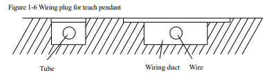
The three-phase power source consists of AC 380V at 50Hz. In cases of temporary power frequency interruptions or voltage drops, the power-off circuit and servo power cutoff mechanisms will be activated. Connect the control cabinet power source to a stable input power source with minimal voltage fluctuations (±10%) to ensure reliable operation.
Connect the power source cable
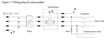
Please follow the provided instructions to connect the power source cable:
Step 1. Unpack the materials and take the power source cable out. Connect the cable to the socket located at the rear of the control cabinet.
Step 2. Connect the robot to the control cabinet.
Step 3. Ensure the shape and size of the cable connectors match and align with the sockets on the robot. Insert the cable into the appropriate socket and secure it firmly.
Connect the teach pendant
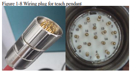
The new version of EWAS Arc Welding Teach Pendant is equipped with an aviation plug, as shown in Figure 1-8
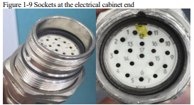
This plug is designed to be compatible with the socket located at the bottom of the control cabinet, as illustrated in Figure 1-9.
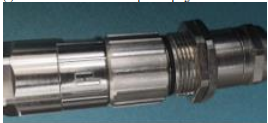
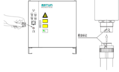
When connecting the wires, ensure that the protrusion and notch of the plug align with the corresponding features of the socket to prevent misalignment. This alignment is crucial to avoid bending the socket when inserting the plug. Once the plug is properly aligned and inserted into the socket, rotate the metal screw cap on the outer side of the plug counterclockwise to securely fasten the wires to the control cabinet, as shown in Figure 1-10.
Figure 1-10: Connection between the teach pendant and the control cabinet
(a) Connection between the teach pendant plug and the control cabinet socket
(b) Schematic diagram of the connection between the teach pendant and the control cabinet
1.5.2 Switching on the main power source
Switch on the main power source
After correctly wiring the teach pendant to the control cabinet and the control cabinet to the robot, users should proceed to power on the teach pendant.
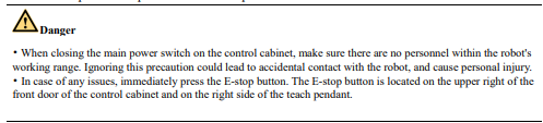
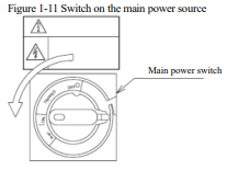
Rotate the red main power switch on the control cabinet to the "ON" position. At this point, the main power will be activated, initiating the initialization diagnostics and reading the current starting position values.
Initialization Diagnostics
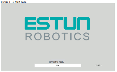
When the main power is turned on, the control cabinet undergoes an initialization diagnostics. On the screen of the teach pendant programmer, three startup screens are sequentially displayed.
Firstly, the progress bar reaches 10%, followed by a transition to 13%. Finally, it begins to increment from 20% to 100%, as illustrated in the figure below.
Status at completion of initialization diagnostics
⚫ Control Cabinet Initialization Completed State
After the control cabinet startup process is finished, the control area and drivers are in normal operational status.
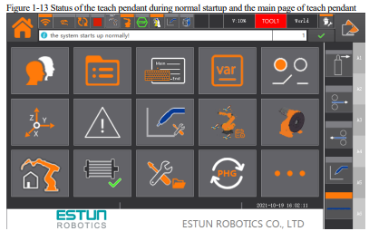
⚫ Teach Pendant Status
Upon completion of the teach pendant startup, the Run indicator light remains illuminated, the Err indicator light is not lit, and the Mot and Vset indicator lights maintain their states from the last usage, as shown in figure below.
1.5.3 Switching on the servo power source
Playback Mode
To enter the playback mode, follow the steps below:
⚫ Close the safety fence and switch the operating mode of the teach pendant to "Auto" mode. The mode indicator in the status bar will change to  .
⚫ Press the "Main Power" button on the control cabinet. Note that the location of the "Main Power" button may vary depending on the actual configuration of the cabinet.
⚫ Press the [Mot] button on the teach pendant to activate the servo power. When the "Mot" indicator light on the upper left corner of the teach pendant illuminates, it indicates that the servo system is in the ready state.
Teaching Mode
To enter the teaching mode, follow the steps below:
⚫ Close the safety fence and switch the operating mode of the teach pendant to "Manual" mode. The mode indicator in the status bar will change to  .
⚫ Press the "Main Power" button on the control cabinet. Note that the location of the "Main Power" button may vary depending on the actual configuration of the cabinet.
⚫ When the operator firmly holds the enable switch on the teach pendant, the servo power will be activated, and the "Mot" indicator light will illuminate.
1.5.4 Cutting off the power source
Cut off the servo power (emergency stop)
When the E-stop button is pressed, the servo power is cut off, and the robot cannot perform any further operations.
⚫ Press the E-stop button located on the front door of the control cabinet or on the teach pendant.
⚫ Once the servo power is cut off, the brake mechanism engages, immobilizing the robot and preventing any further actions.
⚫ The emergency stop can be initiated in any mode (teaching mode, playback mode, or remote mode) at any time
Cut off the main power
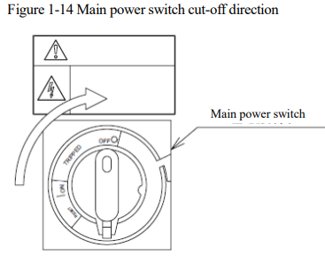
After disconnecting the servo power source, proceed to turn off the main power source. Rotate the main power switch on the front door of the motor control cabinet to the "OFF" position, and the main power source will be disconnected.
1.5.5 Restart
If the user needs to restart the teach pendant, there are three methods available:
⚫ Begin by turning off the main power source, then proceed to turn on the main power source. This method is suitable for situations requiring a rapid restart.
⚫ Gently rotate the screw cap of teach pendant plug in a counterclockwise direction to loosen it from the connector plug attached to the electrical cabinet. Allow a brief period of time before reinserting the connector plug and securing screw cap. It is not recommended to engage in frequent plugging and unplugging actions, as this method may result in wear and tear on the plug.
1.6 Confirmation of Motions
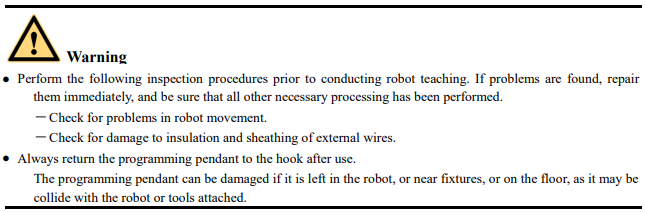
Ensure that you have completed all the necessary operations in "Teaching" mode, and that the system's overall status matches the described state, before proceeding with axis movements.
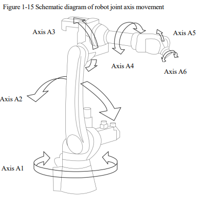
Execute the desired actions for each axis of the robot by pressing the respective "Axis Operation Key" on the teach pendant. The diagram below illustrates the movement of each axis in the joint coordinate system.

Schematic diagram of the movements of each axis in the joint coordinate system
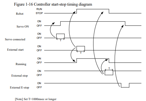
When confirming the motions, note the start and stop sequence of the controller.
1.7Other System Units
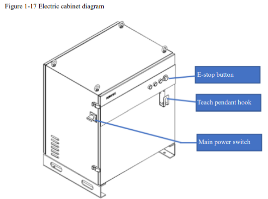
1.7.1 Control cabinet
Take the ERC-S-XXSX(ED3L) vertical control cabinet as an example. Its appearance and the external distribution of buttons are shown in the figure below.
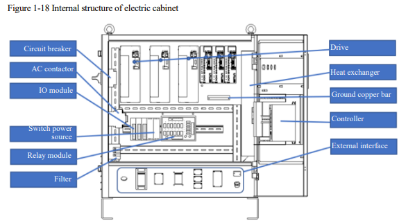
The internal layout of the electrical cabinet is shown (the layout of the electrical cabinet varies for different robots):
1.7.2 Power source unit
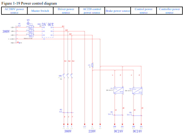
After the 3-phase AC power is filtered by the filter, the 3-phase AC 380V voltage is converted into 3-phase AC 200V through the transformer (for the electric control cabinet of the servo drive supplied by 200V, all electric control cabinets shall use the 400V servo drives, but no transformer is required). Where there’s a temporary power frequency interruption or voltage drop, or any alarm sent from the driver, the power will be cut off for circuit action processing circuit, and the servo power will also be disconnected.
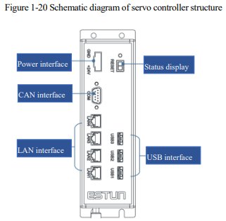
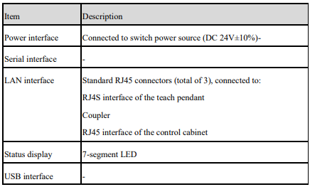
1.7.3 Control unit
Control unit is the motion control center of the robot system by allowing the motion control of the robot and the control of the components working in coordination with the robot in the application of the robot system. It is the core unit that receives commands from the programmer pendant and sends terminal control signals.
1.7.4 Servo drive unit
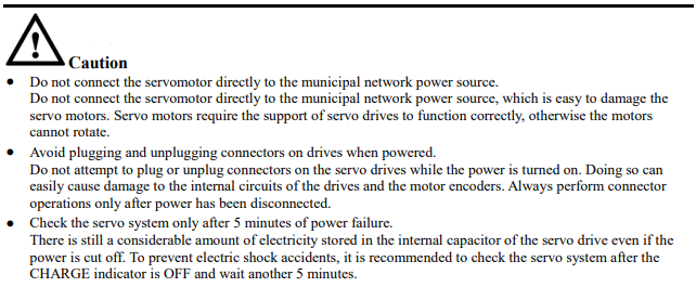
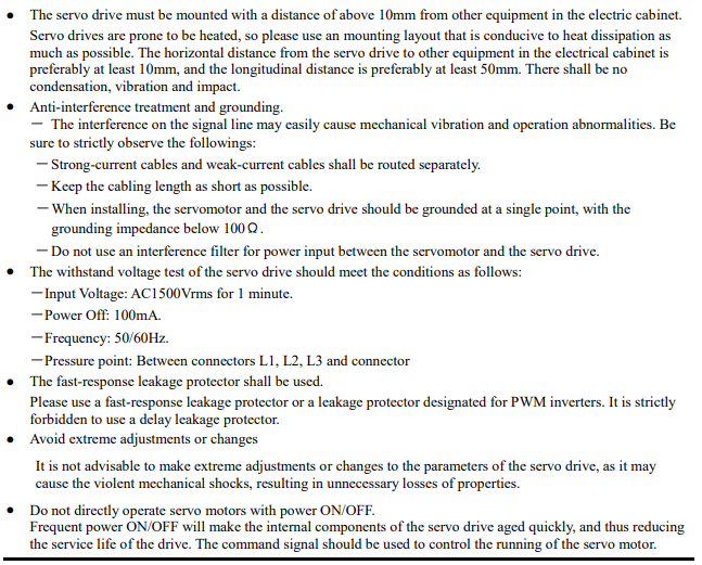
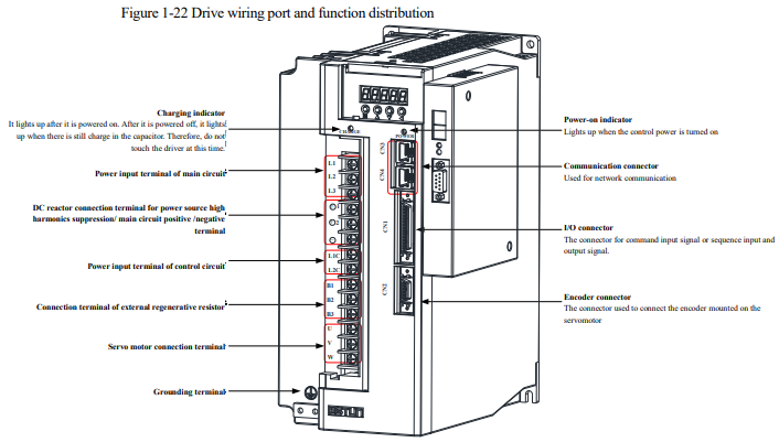
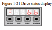
Upon starting, normal display status and wiring ports of the drive are shown in the figure below.
The drive wiring ports and function distribution are shown below.