3. Robot Control Functions
3.1Robot Control State Switching
3.1.1 Control mode
The control modes of the new EWAS Arc Welding Teach Pendant include three options: Teaching (Manual) mode, Playback (Automatic) mode, and Remote mode.
Switching between the control modes of the teach pendant can be accomplished by turning the knob, which has three positions:
⚫ Teaching (Manual) mode;
⚫ Playback (Automatic) mode;
⚫ Remote mode
3.1.2 Jog Coordinates
The robot's jog coordinate systems include Joint Coordinates, Cartesian Coordinates, Tool Coordinates, User Coordinates, External Axis Coordinates, and Positioner Coordinates:
⚫ Joint Coordinates
Each axis of the robot performs individual movements.
⚫ Cartesian Coordinates
The end effector point of the robot can move and rotate along the X, Y, and Z axes defined in the Cartesian coordinates.
⚫ Tool Coordinates
The tool coordinates are defined at the tip of the tool, assuming that the effective direction of the tool mounted on the robot wrist flange is the Z-axis.
Joint Coordinates
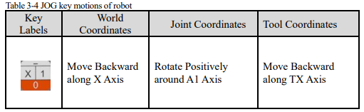
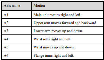
When setting the joint coordinates, the A1, A2, A3, A4, A5 and A6 axis of the robot moves independently. The motion direction of each axis under joint coordinates is shown in figure below.
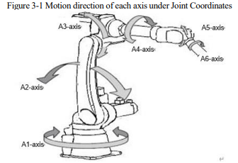
Table 3-1 Names and motion characteristics of each axis in Joint Coordinates

Cartesian Coordinates (World Coordinates)
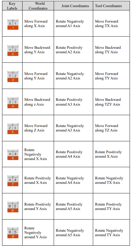
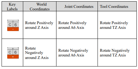
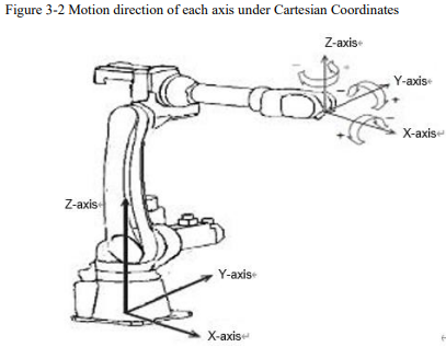
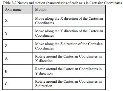
In the Cartesian Coordinates, the control point of robot moves parallel to the X-, Y-, or Z-axes. The motion direction of each axis is shown in figure below.
Tool Coordinates
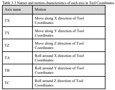
The tool coordinate system designates the effective direction of the tool held by the robot's wrist flange as the Z-axis, and defines the coordinates with respect to the tip of the tool.
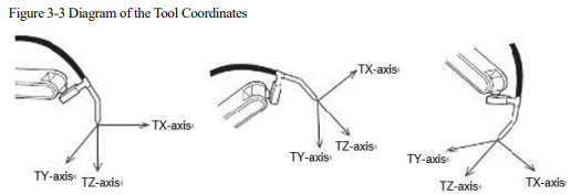
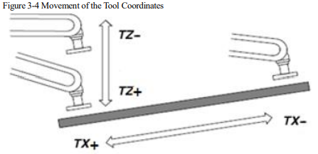
When it is set to Tool Coordinates, the robot control point moves in parallel along the X-, Y-, and Z-axes set at the tip point of the tool. When the Axis Operation Key is pressed, the motions of each axis are shown in table below.
The movement of tool coordinates is based on the effective direction of the tool, but has no connection with the position and posture of the robot. In this case, it would be most suitable for parallel movement operations without changing the posture of the tool relative to the workpiece.
3.1.3 Speed switching
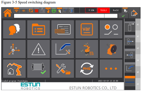
There are five primary methods for adjusting the speed:
⚫ Interface Adjustment: Click on the speed status area in the upper right corner of the teach pendant interface to open a drop-down menu, then select the desired target speed;
⚫ Speed Toggle Key Adjustment: Press the speed toggle key on the teach pendant to adjust between three speed levels: 10%, 50%, and 100%;
⚫ Speed Fine-Tuning: Speed fine-tuning involves incrementing or decrementing the current speed by 1 unit. To achieve this, click the speed+ or speed- key on the teach pendant;
⚫ Speed Adjustment in Increments of 5: Adjusting the speed in increments of 5 units entails increasing or decreasing the current speed by 5 units. To perform this operation, press and hold the speed+ or speed- key on the teach pendant;
⚫ Speed Adjustment in Increments of 10: Adjusting the speed in increments of 10 units involves increasing or decreasing the current speed by 10 units. To execute this action, press the "10x Change" key along with the speed+ key, or press the "10x Change" key along with the speed- key on the teach pendant.
3.2Robot JOG Control
The robot's jog control is accomplished through the teach pendant. If a user intends to manipulate the robot's motion, first adjust the control mode of the teach pendant to "Teach" (Manual) mode. Configure the current jog coordinates and jog mode. Next, lightly depress the hand pressure servo switch using the four fingers of your left hand. Then, use your left thumb or right hand to press a specific jog button interface on the teach pendant within the robot's jog control section.