
5. Programming and Control
5.1Common Programming Commands
This section presents the usage methods for various commonly used programming command on the teach pendant. It covers the meaning of parameters, data types, value ranges, the context of instruction usage, usage recommendations, and important considerations.
5.1.1 Basic motion commands
Basic motion commands are fundamental commands used to control the robot's main body in performing basic trajectory movements. These trajectories encompass point, line, circle, circular arc, curve, spiral, arch, and interpolation motions. The set of commands include: MovJ, MovL, MovC, MovJRel, MovLRel, MovJSearch, MovLSearch, MovLOffset, MovLW, MovCW, MovH, MovArch, OnDistance, OnParameter, and more.
The following section provides a detailed overview of these commands:
MovJ - Joint motion command
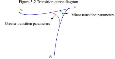
It indicates that each joint of the robot performs point-to-point motion. The end trajectory of the robot is an irregular curve, and the IO command can be operated when the command operates to an end, as shown in figure below.
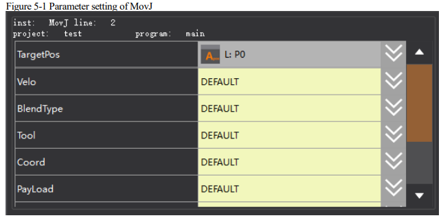
⚫ Target Position: The designated endpoint position for the command, , of which the type can be APOS.
Select an existing point in the drop-down list or create a new variable and teach it in the pop-up dialog box.
⚫ Target speed: The running speed of command.
When setting it to "DEFAULT", the default value V4000 will be used.
When it is set to SPEED variable, you can selected the system pre-defined one, or create it by yourself; the item per controls the MovJ command, which is the percentage of the global speed.
⚫ Transition type: The way of transition when the robot approaches the endpoint.
DEFAULT: Use of the defaulted transition way FINE, i.e. use of no-transition.
FINE: No transition.
RELATIVE: Relative transition.
ABSOLUTE: Absolute transition.
⚫ Transition Value: The transition value when the robot approaches the endpoint.
When setting it to "DEFAULT", the default value C100 will be used.
When it is set to ZONE variable, you can selected the system pre-defined one, or create it by yourself; it means no transition when the variable value is 0; the greater the transition value, the larger the transition radius.
⚫ Tool Parameters: The tool parameters used when the robot executes the path.
When setting it to “DEFAULT”, the tool parameters set last time will be continuously used.
When it is set to TOOL variable, you can selected the system pre-defined one, or create it by yourself. When using a coordinate system different from the current tool parameters, the system will switch the tool parameters to the set ones. If the tool parameters of the path of current segment and the preceding/next segments change, the transition will not be supported.
⚫ Coordinate System Parameters: The coordinate system parameters used by the robot when executing the path.
When setting it to “DEFAULT”, the tool coordinate system set last time will be continuously used.
When it is set to USERCOOR variable, you can selected the system pre-defined one, or create it by yourself.
When a coordinate system different from the current one is used, the system will switch the coordinate system to the set one.
⚫ Workpiece load: The workpiece load parameter used by the robot when executing the path.
It is set to “DEFAULT”, which means to continue to use the workpiece load parameters set last time.
−When it is set to PAYLOAD variable, you can selected the system pre-defined one, or create it by yourself; when a load parameter different from the current workpiece load parameter is used, the system will switch the workpiece load parameter to the set parameter. If the tool parameters of the path of current segment and the preceding/next segments change, the transition will not be supported.
⚫ AddDo: The robot can perform IO operation after executing this command.
NULL: No operation.
IO commands: Executing IO operation. The IO commands currently available are SetDo, SetAo, SetSimDo, SetSimAo, PulseOut, PulseSimOut, SetDO8421, SetSimDO8421, SetDIEdge, and SetSimDIEdge.
[Note]
⚫ The SPEED variables have the parameters detailed as below:
per: The percentage, which affects mainly the motion in the joint coordinates, e.g. MovJ, etc.
tcp: The linear speed of the end, which affects mainly the motion in Cartesian coordinates, e.g. MovL, MovC, etc.
ori: The end posture speed, which affects mainly the motion in the Cartesian coordinates, e.g. MovL, MovC, etc.
exj_l: The external axis linear speed (invalid if no external axis)
exj_r: The rotating speed of external axis (invalid if no external axis)
⚫ The ZONE variables have the following parameters:
per: The percentage, of which the relative transition type is the turning area
dis: The absolute distance, of which the absolute transition type is turning area
vConst: Low-speed constant transition enable state, indicating that the transition speed is constant if it is 1, and track the change of the transition parameters if it is 0.
Example 1:
MovJ (P1, V50, ”RELATIVE”, C100)
The robot travels to point P1 at the speed of V50, and there is a transition with the next path. The
transition value is 100%.
Example 2:
MovJ (P2, V50, ”RELATIVE”, C0)Do SetDo(DO0,0)
The robot travels to point P2 at the speed of V50 without transition. Set DO0 to 0 when it travels to
point P2.
MovL- Linear motion command
MovL is the linear motion command, through which the TCP point of the robot can be moved linearly to the target position at the set speed. If the start and end postures of the motion differ, then during operation the posture will synchronously rotate to the ending posture along with the position. It is the same as MovJ. An additional IO operation can be performed when the command is executed. The parameter setting of MovL is similar to MovJ, but its target speed is an absolute speed value, rather than the percentage.
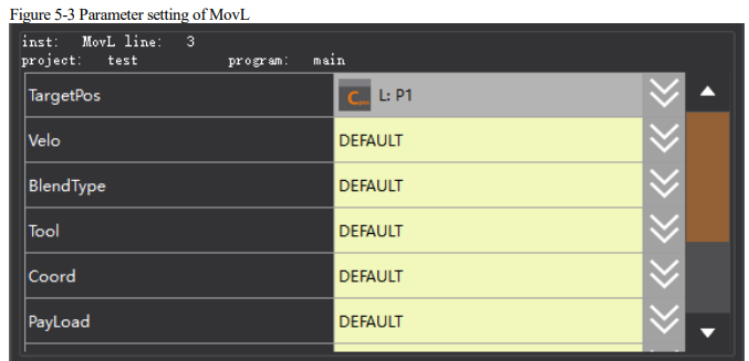
⚫ Target Position: The commanded ending position, which can be of type APOS or CPOS.
Select an existing point in the drop-down list or create a new variable and teach it in the pop-up dialog box.
When selecting a variable of type CPOS, the target position is influenced by the configuration of the confdata.
However, if the mode value is set to -1, the endpoint position is not constrained by the confdata values. Instead, the robot will arrive at the target position using the most optimal solution available.
⚫ Target speed: The running speed of command.
When setting it to "DEFAULT", the default value V4000 will be used.
When it is set to SPEED variable, you can selected the system pre-defined one, or create it by yourself; the item per controls the MovJ command, which is the percentage of the global speed.
⚫ Transition type: The way of transition when the robot approaches the endpoint.
DEFAULT: Use of the defaulted transition way FINE, i.e. use of no-transition.
FINE: No transition.
RELATIVE: Relative transition.
ABSOLUTE: Absolute transition.
⚫ Transition Value: The transition value when the robot approaches the endpoint.
When setting it to "DEFAULT", the default value C100 will be used.
When it is set to ZONE variable, you can selected the system pre-defined one, or create it by yourself; it means no transition when the variable value is 0; the greater the transition value, the larger the transition radius.
⚫ Tool Parameters: The tool parameters used when the robot executes the path.
When setting it to “DEFAULT”, the tool parameters set last time will be continuously used.
When it is set to TOOL variable, you can selected the system pre-defined one, or create it by yourself. When using a coordinate system different from the current tool parameters, the system will switch the tool parameters to the set ones. If the tool parameters of the path of current segment and the preceding/next segments change, the transition will not be supported.
⚫ Coordinate System Parameters: The coordinate system parameters used by the robot when executing the path.
When setting it to “DEFAULT”, the tool coordinate system set last time will be continuously used.
When it is set to USERCOOR variable, you can selected the system pre-defined one, or create it by yourself.
When a coordinate system different from the current one is used, the system will switch the coordinate system to the set one.
⚫ Workpiece load: The workpiece load parameter used by the robot when executing the path.
It is set to “DEFAULT”, which means to continue to use the workpiece load parameters set last time.
−When it is set to PAYLOAD variable, you can selected the system pre-defined one, or create it by yourself;
when a load parameter different from the current workpiece load parameter is used, the system will switch the workpiece load parameter to the set parameter. If the tool parameters of the path of current segment and the preceding/next segments change, the transition will not be supported.
⚫ AddDo: The robot can perform IO operation after executing this command.
NULL: No operation.
IO commands: Executing IO operation. The IO commands currently available are SetDo, SetAo, SetSimDo, SetSimAo, PulseOut, PulseSimOut, SetDO8421, SetSimDO8421, SetDIEdge, and SetSimDIEdge.
MovC - Arc motion command
Arc command refers to the circular motion made by the robot’s TCP point from the starting position to the target by passing through the middle position. If the start and end postures of the motion are different, the posture will rotate to the end posture synchronously with the position, but it may not necessarily pass through the middle position.
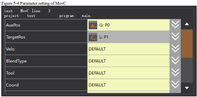
⚫ Middle position: The position of the auxiliary point in the middle of the arc.
⚫ Target position: The final position of the arc.
⚫ Target speed: The running speed of command.
When setting it to "DEFAULT", the default value V4000 will be used.
When it is set to SPEED variable, you can select the system pre-defined one, or create it by yourself.
⚫ Transition type: The way of transition when the robot approaches the endpoint.
DEFAULT: Use of the defaulted transition way FINE, i.e. use of no-transition.
FINE: No transition.
RELATIVE: Relative transition.
ABSOLUTE: Absolute transition.
⚫ Transition Value: The transition value when the robot approaches the endpoint.
When setting it to "DEFAULT", the default value C100 will be used.
When it is set to ZONE variable, you can selected the system pre-defined one, or create it by yourself; it means no transition when the variable value is 0; the greater the transition value, the larger the transition radius.
⚫ Tool Parameters: The tool parameters used when the robot executes the path.
When setting it to “DEFAULT”, the tool parameters set last time will be continuously used.
When it is set to TOOL variable, you can selected the system pre-defined one, or create it by yourself. When using a coordinate system different from the current tool parameters, the system will switch the tool parameters to the set ones. If the tool parameters of the path of current segment and the preceding/next segments change, the transition will not be supported.
⚫ Coordinate System Parameters: The coordinate system parameters used by the robot when executing the path.
When setting it to “DEFAULT”, the tool coordinate system set last time will be continuously used.
When it is set to USERCOOR variable, you can selected the system pre-defined one, or create it by yourself.
When a coordinate system different from the current one is used, the system will switch the coordinate system to the set one.
When it is set to external tool coordinates, the motion of robot is relative to the external tool coordinates, and the target speed of command is relative to the external tool coordinates. External TCP functions support only the transition between the reference coordinate system is the same external tool coordinates.
When setting it to the positioner coordinates, the robot’s motion is relative to the positioner coordinates, and the target speed of command is relative to the positioner flange. The POSITIONER function supports only the transition between the same positioner
⚫ Workpiece load: The workpiece load parameter used by the robot when executing the path.
It is set to “DEFAULT”, which means to continue to use the workpiece load parameters set last time.
−When it is set to PAYLOAD variable, you can selected the system pre-defined one, or create it by yourself;
when a load parameter different from the current workpiece load parameter is used, the system will switch the workpiece load parameter to the set parameter. If the tool parameters of the path of current segment and the preceding/next segments change, the transition will not be supported.
⚫ Rate type: Whether the robot's commanded speed is affected by the global multiplier of the teach pendant when executing this path.
DEFAULT: Same as GOVRON, i.e. the commanded speed is affected by the global multiplier of the teach pendant.
GOVRON: The commanded speed is affected by the global multiplier of the teach pendant.
GOVROFF: The commanded speed is not affected by the global multiplier of the teach pendant.
⚫ AddDo: The robot can perform IO operation after executing this command.
NULL: No operation.
IO Command: Executing IO operation.
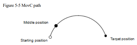
This command must satisfy following requirements: When the end of the robot TCP performs a full circular motion, two MovC commands must be executed or the MovCircle command must be used.
MovCircle - Circular motion command
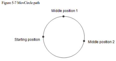
MovCircle command means that the robot TCP point moves in a full circle from the start position to the start position through the auxiliary point 1 and auxiliary point 2 positions, with the pose remaining constant during the movement.
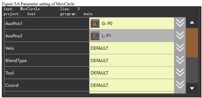
⚫ Middle Position 1: The position 1 of the middle auxiliary point of the full circle, which is used to determine the size and movement direction of the arc. The pose of this point will not affect the final trajectory.
⚫ Middle Position 2: The position 2 of the middle auxiliary point of the full circle, which is used to determine the size and movement direction of the arc. The pose of this point will not affect the final trajectory.
⚫ Target speed: The running speed of command.
When setting it to "DEFAULT", the default value V4000 will be used.
When it is set to SPEED variable, you can select the system pre-defined one, or create it by yourself.
⚫ Transition type: The way of transition when the robot approaches the endpoint.
DEFAULT: Use of the defaulted transition way FINE, i.e. use of no-transition.
FINE: No transition.
RELATIVE: Relative transition.
ABSOLUTE: Absolute transition.
⚫ Transition Value: The transition value when the robot approaches the endpoint.
When setting it to "DEFAULT", the default value C100 will be used.
When it is set to ZONE variable, you can selected the system pre-defined one, or create it by yourself; it means no transition when the variable value is 0; the greater the transition value, the larger the transition radius.
⚫ Tool Parameters: The tool parameters used when the robot executes the path.
When setting it to “DEFAULT”, the tool parameters set last time will be continuously used.
When it is set to TOOL variable, you can selected the system pre-defined one, or create it by yourself. When using a coordinate system different from the current tool parameters, the system will switch the tool parameters to the set ones. If the tool parameters of the path of current segment and the preceding/next segments change, the transition will not be supported.
⚫ Coordinate System Parameters: The coordinate system parameters used by the robot when executing the path.
When setting it to “DEFAULT”, the tool coordinate system set last time will be continuously used.
When it is set to USERCOOR variable, you can selected the system pre-defined one, or create it by yourself.
When a coordinate system different from the current one is used, the system will switch the coordinate system to the set one.
When it is set to external tool coordinates, the motion of robot is relative to the external tool coordinates, and the target speed of command is relative to the external tool coordinates. External TCP functions support only the transition between the reference coordinate system is the same external tool coordinates.
When setting it to the positioner coordinates, the robot’s motion is relative to the positioner coordinates, and the target speed of command is relative to the positioner flange. The POSITIONER function supports only the transition between the same positioner.
⚫ Workpiece load: The workpiece load parameter used by the robot when executing the path.
It is set to “DEFAULT”, which means to continue to use the workpiece load parameters set last time.
−When it is set to PAYLOAD variable, you can selected the system pre-defined one, or create it by yourself;
when a load parameter different from the current workpiece load parameter is used, the system will switch the workpiece load parameter to the set parameter. If the tool parameters of the path of current segment and the preceding/next segments change, the transition will not be supported.
⚫ Rate type: Whether the robot's commanded speed is affected by the global multiplier of the teach pendant when executing this path.
DEFAULT: Same as GOVRON, i.e. the commanded speed is affected by the global multiplier of the teach pendant.
GOVRON: The commanded speed is affected by the global multiplier of the teach pendant.
GOVROFF: The commanded speed is not affected by the global multiplier of the teach pendant.
⚫ AddDo: The robot can perform IO operation after executing this command.
NULL: No operation.
IO Command: Executing IO operation.
MovJRel - Joint space position offset command
The MovJ interpolation relative offset command. It works by taking the current robot position or the target position of the previous motion command as the starting point, and then perform the robot’s relative motion operation.
Unlike the commands such as MovJ, the target relative position value used by this command cannot be obtained through teaching. User needs to create a new joint relative position variable in the list of variables before, and then select it from the drop-down list.
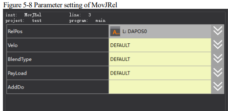
⚫ Target Relative Position: The position increment the robot will move when executing this command.
⚫ Target speed: The running speed of command.
When setting it to "DEFAULT", the default value V4000 will be used.
When it is set to SPEED variable, you can select the system pre-defined one, or create it by yourself.
⚫ Transition type: The way of transition when the robot approaches the endpoint.
DEFAULT: Use of the defaulted transition way FINE, i.e. use of no-transition.
FINE: No transition.
RELATIVE: Relative transition.
ABSOLUTE: Absolute transition.
⚫ Transition Value: The transition value when the robot approaches the endpoint.
When setting it to "DEFAULT", the default value C100 will be used.
When it is set to ZONE variable, you can selected the system pre-defined one, or create it by yourself; it means no transition when the variable value is 0; the greater the transition value, the larger the transition radius.
⚫ Workpiece load: The workpiece load parameter used by the robot when executing the path.
It is set to “DEFAULT”, which means to continue to use the workpiece load parameters set last time.
−When it is set to PAYLOAD variable, you can selected the system pre-defined one, or create it by yourself;
when a load parameter different from the current workpiece load parameter is used, the system will switch the workpiece load parameter to the set parameter. If the tool parameters of the path of current segment and the preceding/next segments change, the transition will not be supported.
⚫ AddDo: Robot will perform IO operation after executing this command.
MovLRel - Cartesian space position offset command
The MovJ interpolation relative offset command. It works by taking the current robot position or the target position of the previous motion command as the starting point, and then performs an offset motion relative to the coordinate system or tool.
Unlike the commands such as MovL, the target relative position value used by this command cannot be obtained through teaching. User needs to create a new joint relative position variable in the list of variables before, and then select it from the drop-down list.
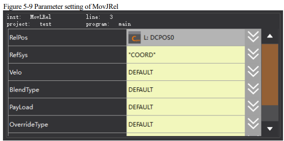
⚫ Target Relative Position: The position increment the robot will move when executing this command.
⚫ Reference Coordinates: coordinate system offset or tool offset selection;
Coord: offset relative to the current user coordinates;
Tool: offset relative to the tool coordinates, i.e. translation or rotation with reference to Tx, Ty, Tz.
⚫ Target speed: The running speed of command.
When setting it to "DEFAULT", the default value V4000 will be used.
When it is set to SPEED variable, you can select the system pre-defined one, or create it by yourself.
⚫ Transition type: The way of transition when the robot approaches the endpoint.
DEFAULT: Use of the defaulted transition way FINE, i.e. use of no-transition.
FINE: No transition.
RELATIVE: Relative transition.
ABSOLUTE: Absolute transition.
⚫ Transition Value: The transition value when the robot approaches the endpoint.
When setting it to "DEFAULT", the default value C100 will be used.
When it is set to ZONE variable, you can selected the system pre-defined one, or create it by yourself; it means no transition when the variable value is 0; the greater the transition value, the larger the transition radius.
⚫ Workpiece load: The workpiece load parameter used by the robot when executing the path.
It is set to “DEFAULT”, which means to continue to use the workpiece load parameters set last time.
−When it is set to PAYLOAD variable, you can selected the system pre-defined one, or create it by yourself;
when a load parameter different from the current workpiece load parameter is used, the system will switch the workpiece load parameter to the set parameter. If the tool parameters of the path of current segment and the preceding/next segments change, the transition will not be supported.
⚫ Rate type: Whether the robot’s commanded speed is affected by the global multiplier.
DEFAULT: Same as GOVRON, i.e. the commanded speed is affected by the global multiplier of the teach pendant.
GOVRON: The commanded speed is affected by the global multiplier.
GOVROFF: The commanded speed is not affected by the global multiplier.
⚫ Rate type: Whether the robot's commanded speed is affected by the global multiplier of the teach pendant when executing this path.
DEFAULT: Same as GOVRON, i.e. the commanded speed is affected by the global multiplier of the teach pendant.
GOVRON: The commanded speed is affected by the global multiplier of the teach pendant.
GOVROFF: The commanded speed is not affected by the global multiplier of the teach pendant.
⚫ AddDo: Robot will perform IO operation after executing this command.
MovJSearch - Joint searching command
A search command, which performs IO detection or torque detection when executing the MovJ
command.
When the search condition is IO detection and the value of index IO reaches the triggered value, stop running the command and continue to execute the next command.
When the search condition is torque detection and the value of the index axis torque reaches the triggered value, stop running the command and continue to execute the next command.
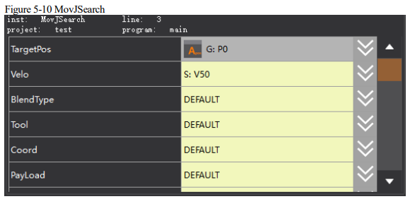
⚫ Target Position, Target Speed, Tool Parameters, Coordinate System Parameters, Workpiece Load, and AddDo: These parameters carry the same meanings as in the MovJ command.
⚫ Transition type: The way of transition when the robot approaches the endpoint.
DEFAULT: Use of the defaulted transition way FINE, i.e. use of no-transition.
FINE: No transition.
Note: In the current version, MovJSearch does not support transitional planning with the subsequent motion command.
⚫ Type of detection:
DITrig: Physical digital IO input detection.
AITrig: Physical analogue IO input detection.
SIMDITrig: Virtual digital IO input detection.
SIMAITrig: Virtual analogue IO input detection.
TorqTrig: Torque detection.
⚫ Trigger index:
−For InputTrig, this parameter indicates the IO port number to be detected.
−For TorqTirg, this parameter indicates the axis number to be detected.
⚫ Trigger value:
−For InputTrig, the threshold for IO detection.
−For TorqTirg the threshold for torque detection, which is expressed in thousandths of the rated torque.
⚫ STOP type: The way to stop when a signal is detected.
DEFAULT: Stops immediately;
HARDSTOP: Stops immediately;
SOFTSTOP: Stop at reduced speed.
⚫ Decel Factor: The value is valid when "SOFTSTOP" is selected as "Stop Type". It is used to adjust the Decel/Accel factor, the greater the value, the faster the deceleration.
⚫ Return Value: A return value of 1 indicates successful signal detection during searching, while a return value of 0 signifies the absence of signal detection.
[Note]
In the current version, MovJSearch does not support transitional planning with the subsequent motion command.
MovLSearch - Linear search command
The Search Command refers to IO detection or torque detection while executing this MovL command, which is similar to MovJSearch.
[Note]
In the current version, MovLSearch does not support transitional planning with the subsequent motion command.
MovLOffset - Linear offset motion command
MovL Interpolation Relative Offset command. This command specifies a reference position as the starting position for an offset movement relative to the coordinates or tool.
It differs from MovLRel only in that it specifies the starting point of the offset movement, not necessarily the current position or the endpoint of the previous command, and all other functions are the same.
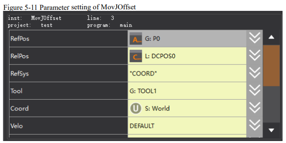
The new command parameters compared to MovLRel are as follows:
⚫ Reference position: The starting point of the offset movement (APos or CPos).
⚫ Tool parameters: Information on the tool to which the reference position belongs.
⚫ Coordinate system parameters: Information on the coordinate system to which the reference position belongs.
MovLW - Linear weave command
Weave command, which performs the arc swinging motion in the forward direction based on the set swing frequency and amplitude.
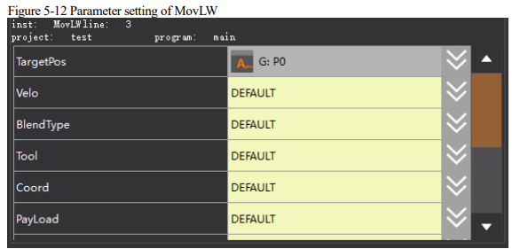
⚫ Target position: The final position of the command (the position point of APOS or CPOS).
Select an existing point in the drop-down list or create a new variable and teach it in the pop-up dialog box.
⚫ Target speed: The running speed of command.
When setting it to "DEFAULT", the default value V4000 will be used.
When it is set to SPEED variable, you can select the system pre-defined one, or create it by yourself.
⚫ Transition type: The way of transition when the robot approaches the endpoint.
DEFAULT: Use of the defaulted transition way FINE, i.e. use of no-transition.
FINE: No transition.
RELATIVE: Relative transition.
ABSOLUTE: Absolute transition.
⚫ Transition Value: The transition value when the robot approaches the endpoint.
When setting it to "DEFAULT", the default value C100 will be used.
When it is set to ZONE variable, you can selected the system pre-defined one, or create it by yourself; it means no transition when the variable value is 0; the greater the transition value, the larger the transition radius.
⚫ Tool Parameters: The tool parameters used when the robot executes the path.
When setting it to “DEFAULT”, the tool parameters set last time will be continuously used.
When it is set to TOOL variable, you can selected the system pre-defined one, or create it by yourself. When using a coordinate system different from the current tool parameters, the system will switch the tool parameters to the set ones. If the tool parameters of the path of current segment and the preceding/next segments change, the transition will not be supported.
⚫ Coordinate System Parameters: The coordinate system parameters used by the robot when executing the path.
When setting it to “DEFAULT”, the tool coordinate system set last time will be continuously used.
When it is set to USERCOOR variable, you can selected the system pre-defined one, or create it by yourself.
When a coordinate system different from the current one is used, the system will switch the coordinate system to the set one.
When setting it to the positioner coordinates, the robot’s motion is relative to the positioner coordinates, and the target speed of command is relative to the positioner flange. The POSITIONER function supports only the transition between the same positioner.
⚫ Workpiece load: The workpiece load parameter used by the robot when executing the path.
It is set to “DEFAULT”, which means to continue to use the workpiece load parameters set last time.
−When it is set to PAYLOAD variable, you can selected the system pre-defined one, or create it by yourself;
when a load parameter different from the current workpiece load parameter is used, the system will switch the workpiece load parameter to the set parameter. If the tool parameters of the path of current segment and the preceding/next segments change, the transition will not be supported.
⚫ Swinging arc variable: The weaving parameter.
The swing frequency, amplitude, stop time, rotation, etc. can be set.
⚫ Rate type: Whether the robot's commanded speed is affected by the global multiplier of the teach pendant when executing this path.
DEFAULT: Same as GOVRON, i.e. the commanded speed is affected by the global multiplier of the teach pendant.
GOVRON: The commanded speed is affected by the global multiplier of the teach pendant.
GOVROFF: The commanded speed is not affected by the global multiplier of the teach pendant.
⚫ AddDo: The robot can perform IO operation after executing this command.
NULL: No operation.
IO Command: Executing IO operation.
[Note]
The WEAVE variable has the following parameters:
⚫ Type: Weave type of robot. It is a sine Weave when the value is 1, and is a triangular Weave when the value is 2.
⚫ Freq: The frequency when the robot weaves, in Hz.
⚫ Amp_L: The left amplitude when the robot weaves, in mm.
⚫ Amp_R: The right amplitude when the robot weaves, in mm.
⚫ StopTime_L: The time when robot stops at wave peak. It refers to the time in ms at which the weaving stops when it reaches the left amplitude.
⚫ StopTime_C: The time when robot stops at the middle. It refers to the time in ms at which the weaving stops when it reaches the middle position.
⚫ StopTime_R: The time when robot stops at wave trough. It refers to the time in ms at which the weaving stops when it reaches the right amplitude.
⚫ RotAngle_X: The rotating angle of the weaving reference plane around the weaving direction. This parameter is used to determine the final weaving plane, in deg.
⚫ RotAngle_Z: The rotating angle around the normal vector of the weaving plane, which determines the shape of the sine weave, in deg.
[Caution]
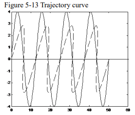
⚫ The normal vector of the plane determined by the motion path and the Tz direction of tool coordinates, and the plane formed by the motion path is the reference plane for weaving.
⚫ The function of RotAngle_Z is in the figure below: it is indicated by a solid line if RotAngle_Z=0 is a solid line, and a dotted line if it is not 0.
MovCW - Arc weave motion command
Similar to MovLW.
MovCircleW - Circular weave motion command
Similar to MovLW.
MovH - Helical motion command
The helical motion command, through which the TCP point of the robot can perform Helical motion to the target position. If the start and end postures of the motion are different, the posture will rotate to the ending posture synchronously with the position.
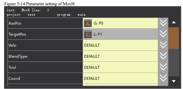
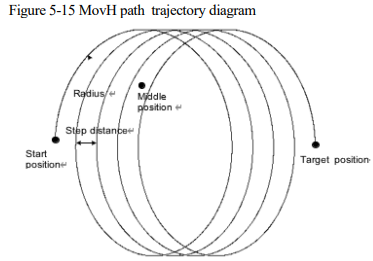
⚫ Middle position: The position of the helical middle auxiliary point. The auxiliary point is used to determine the helical plane and the helical direction (precession in clockwise and counterclockwise). The helical movement may not pass through the auxiliary point
⚫ Target position: Helical end position
⚫ Target speed: the speed at which the command position is run, where the parameter tcp is valid for the linear speed of the command and ori is valid for the posture speed. The maximum path linear speed of the helical line is 0.25 times the maximum system speed
⚫ Transition type: Transition not supported
⚫ Tool Parameters: The tool parameters used when the robot executes the path.
When setting it to “DEFAULT”, the tool parameters set last time will be continuously used.
When it is set to TOOL variable, you can selected the system pre-defined one, or create it by yourself. When using a coordinate system different from the current tool parameters, the system will switch the tool parameters to the set ones. If the tool parameters of the path of current segment and the preceding/next segments change, the transition will not be supported.
⚫ Coordinate System Parameters: The coordinate system parameters used by the robot when executing the path.
When setting it to “DEFAULT”, the tool coordinate system set last time will be continuously used.
When it is set to USERCOOR variable, you can selected the system pre-defined one, or create it by yourself.
When a coordinate system different from the current one is used, the system will switch the coordinate system to the set one.
When setting it to the positioner coordinates, the robot’s motion is relative to the positioner coordinates, and the target speed of command is relative to the positioner flange. The POSITIONER function supports only the transition between the same positioner.
⚫ Workpiece load: The workpiece load parameter used by the robot when executing the path.
It is set to “DEFAULT”, which means to continue to use the workpiece load parameters set last time.
When it is set to PAYLOAD variable, you can selected the system pre-defined one, or create it by yourself;
when a load parameter different from the current workpiece load parameter is used, the system will switch the workpiece load parameter to the set parameter. If the workpiece load of the path of current segment and the preceding/next segments change, the transition will not be supported.
⚫ Radius: Helical line radius, in mm
⚫ Stepping distance: The stepping distance when the helical line makes one revolution, in mm
⚫ AddDo: The robot can perform IO operations after executing this command
[Note]
For Helical motion, the transition and WaitFinish are not supported.
Example:
MovL (P1, V50, ”RELATIVE”, C50)
MovH (P2,P3, V100, ”FINE”,nullTool,World,PayLoad0,10,5)
The robot will move to point P1 at the speed of V50, and then when executing the Helical command
by taking point P1 as the starting point of the motion, and determining the Helical motion plane
using the three points P1, P2, and P3, while determining the precession direction using point P2.
Then, perform the precession to the endpoint P3 at a helical radius of 10mm and the step distance of
5mm. The entire helical motion is finished by this moment.
MovArch - Arch-shaped motion command
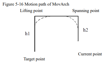
MovArch is an arch-shaped motion command, through which the TCP point of the robot will be elevated to a certain height from the current point or the end point of the previous path at a set speed, then move linearly to the point of the same height of the target position, and descend to such height to reach the target point. Same as the normal motion commands, additional IO operation can be performed when the command is executed. The target speed of the command denoted as the
percentage.
The figure below illustrates the full motion path. The robot raises the height h1 from the current point to reach the lifting point, then pans to the span point, and finally lowers to the target point with a height of h2. The full motion path becomes a “door-shaped”. If the turning parameters are required, it will turn according to the dotted line shown in the figure. For the Scara model, only the joint 3 move in the lifting and lowering process, and only the joint 1, 2 and 4 move in the translation process. The entire motion process is a point-to-point joint motion.
[Note]
This command is only for scara model currently.
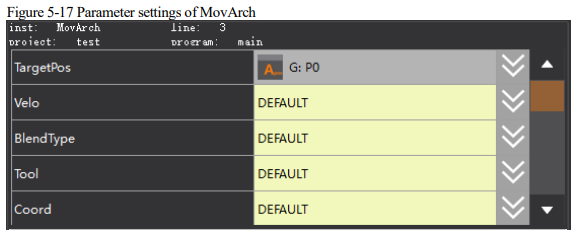
⚫ Target position: The final position of the command (the position point of APOS or CPOS).
Select an existing point in the drop-down list or create a new variable and teach it in the pop-up dialog box.
⚫ Target speed: The running speed of the command (see MovJ notes for details).
⚫ Transition type: The way of transition when the robot approaches the endpoint.
DEFAULT: Use of the defaulted transition way FINE, i.e. use of no-transition.
FINE: No transition.
RELATIVE: Relative transition.
ABSOLUTE: Absolute transition.
⚫ Transition Value: The transition value when the robot approaches the endpoint.
When setting it to "DEFAULT", the default value C100 will be used.
When it is set to ZONE variable, you can selected the system pre-defined one, or create it by yourself; it means no transition when the variable value is 0; the greater the transition value, the larger the transition radius.
⚫ Tool Parameters: The tool parameters used when the robot executes the path.
When setting it to “DEFAULT”, the tool parameters set last time will be continuously used.
When it is set to TOOL variable, you can selected the system pre-defined one, or create it by yourself. When using a coordinate system different from the current tool parameters, the system will switch the tool parameters to the set ones. If the tool parameters of the path of current segment and the preceding/next segments change, the transition will not be supported.
⚫ Coordinate System Parameters: The coordinate system parameters used by the robot when executing the path.
When setting it to “DEFAULT”, the tool coordinate system set last time will be continuously used.
When it is set to USERCOOR variable, you can selected the system pre-defined one, or create it by yourself.
When a coordinate system different from the current one is used, the system will switch the coordinate system to the set one.
⚫ Workpiece load: The workpiece load parameter used by the robot when executing the path.
It is set to “DEFAULT”, which means to continue to use the workpiece load parameters set last time.
−When it is set to PAYLOAD variable, you can selected the system pre-defined one, or create it by yourself;
when a load parameter different from the current workpiece load parameter is used, the system will switch the workpiece load parameter to the set parameter. If the tool parameters of the path of current segment and the preceding/next segments change, the transition will not be supported.
⚫ Lifting height: The height that the robot needs to elevate when performing arching motion.
⚫ Rotating angle value: The value (variable) that the robot needs to rotate when performing arching motion.
⚫ AddDo: The robot can perform IO operation after executing this command.
NULL: No operation.
IO Command: Executing IO operation.
OnDistance - Distance trigger command
The distance trigger command. The controller can trigger some operations when moving a certain distance from the starting point or to the end point by not interrupting the transition, e.g. assigning values, setting IO and so on.
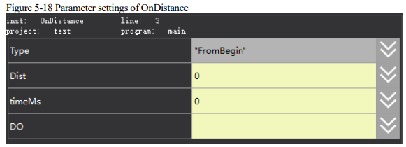
When the trigger type is set to judge from the starting point, the controller will enter the trigger waiting after the robot moves to the set distance, and after delaying the trigger time, it will start to perform the related trigger operations.
When the trigger type is set to judge from the endpoint, the controller will enter the trigger waiting after the robot moves to the set distance, and after delaying the trigger time, it will start to perform the related trigger operations.
⚫ Trigger type: Specify whether the current trigger is made at a certain distance from the start point or at a distance to the endpoint.
⚫ Trigger distance: The distance parameter for the trigger.
⚫ Trigger time: The time delayed for trigger after the trigger condition is met.
It means to trigger earlier when being set to negative number.
⚫ Trigger operation: The robot needs to perform the trigger operations after the trigger condition is met.
Example 1: The Do operation is executed at a distance of 200ms from the starting point of the path from P1 to P2, with a delay of 100ms.

Example 2: The Do operation is executed at a distance of 200ms from the end point of the path from P1 to P2, with a delay of 100ms.

[Caution]
⚫ When the distance trigger is met and the time trigger is still delayed, if the robot has completed the current path, the trigger will be executed later after the conditions for triggering is satisfied.
⚫ When the set trigger distance exceeds the path length, there will be two cases: when it is the start point trigger, the trigger judgment will be executed when the robot moves to the endpoint. When it is the endpoint trigger, the trigger judgment will be executed at the starting point. Trigger immediately when the relevant conditions are met.
⚫ There’re multiple trigger commands between the two paths. The respective detections will be made before the trigger execution. They works in a way not interfering with each other.
⚫ Execute the motion commands in Cartesian coordinates before executing OnDistance, otherwise OnDistance will not work, and the status bar will prompt that the operation is invalid, but the system operation will not be affected.
⚫ Only waiting commands can be inserted between OnDistance and the next motion command in Cartesian coordinate system, otherwise an error will be reported. The waiting commands can be Wait, Waitcondition WaitFinish and so on.
OnParameter - Distance percentage trigger command
The distance percentage trigger command. It is used to trigger some operations (e.g. assignment, setting IO and other shortcut operations) at a certain point of the linear path without interrupting the transition.
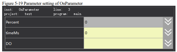
When the robot moves to the set path of trigger percentage, the controller enters the trigger waiting, and it starts to execute the related trigger operation after the trigger time is delayed.
⚫ Path percentage: The percentage of the path that needs to be triggered.
⚫ Trigger time: The time delayed for trigger after the trigger condition is met.
It means to trigger earlier when being set to negative number.
⚫ Trigger operation: The robot needs to perform the trigger operations after the trigger condition is met.
Example: When traveling to a distance of 60% from P1 to P2, the DO operation will be executed with a delay of 500ms.

5.1.2 Basic commands of arc welding
This section provides an introduction to fundamental arc welding commands. These commands are frequently used by users in arc welding scenarios and are designed specifically for the EWAS Arc
Welding Teach Pendant.
These commands include as follows:
ARC_ON,ARC_OFF,ARC_SET,ARC_WireFeed,ARC_WireFeedBack,ARC_WireSpeed,ARC_Ga sFeed,ARC_Line,ARC_Circ,SetWeaveCFG,ARC_StichL,ARC_SegmentL,ARC_StichC,ARC_LW ,ARC_CW,ARC_Fast,WaitArcOn,SetBlendParam,SetBurnTime,ARC_Count,SetCloosJOB.
These commands are described in detail below:
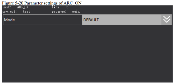
ARC_ON
Arc striking command, as shown in figure below.
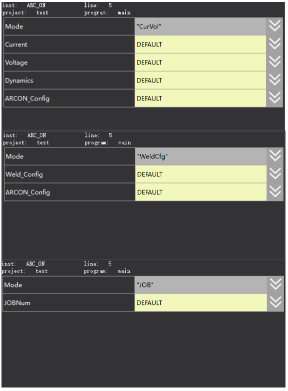
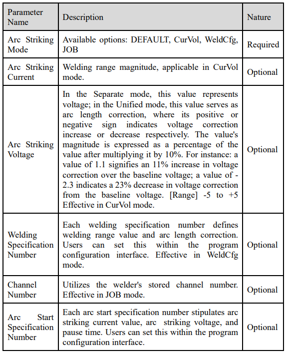
ARC_OFF
Arc stopping command, as shown in figure below
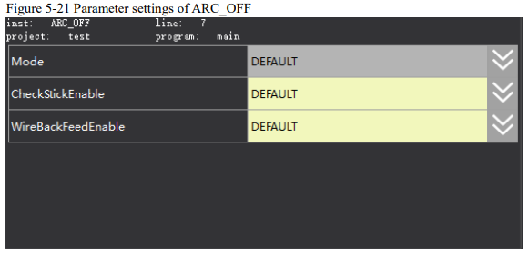
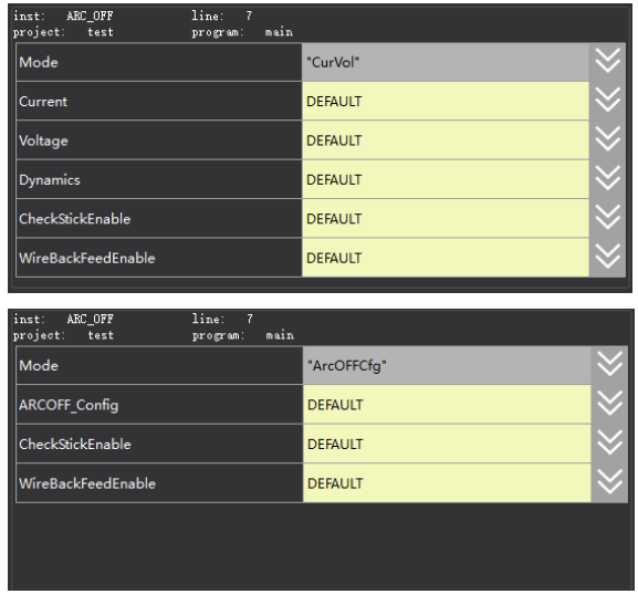
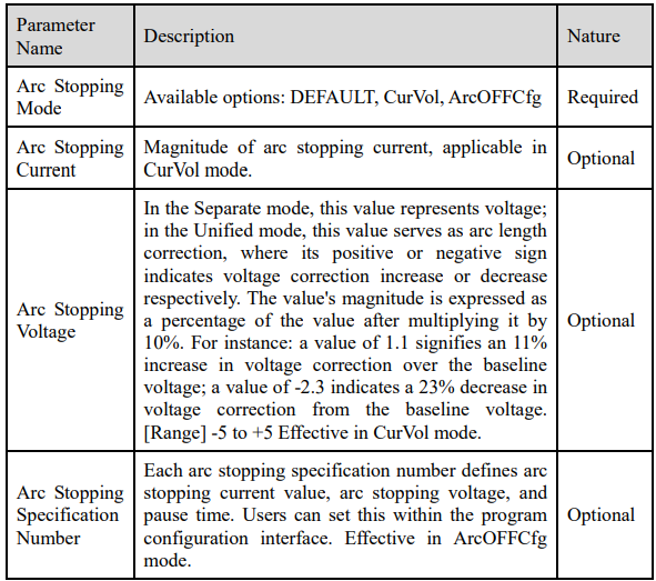
ARC_SET - Welding arc striking and arc stopping current and voltage settings
The command for setting welding arc striking and arc stopping current and voltage, as shown in figure below.
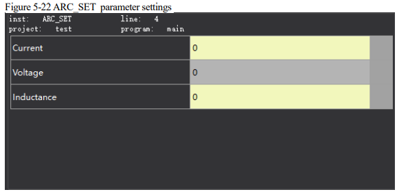
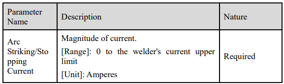
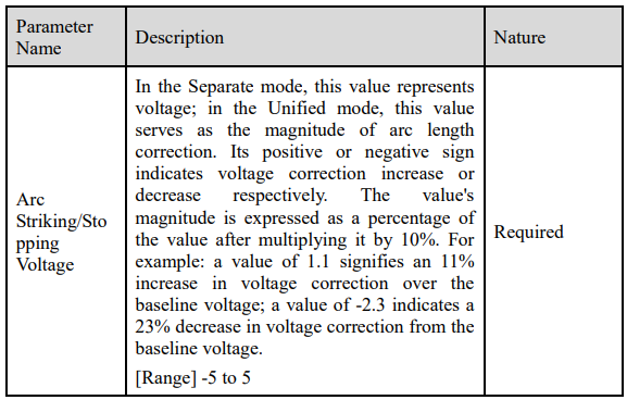
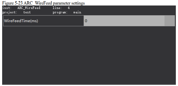
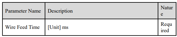
ARC_WireFeed
The wire feed command, as shown in figure below.
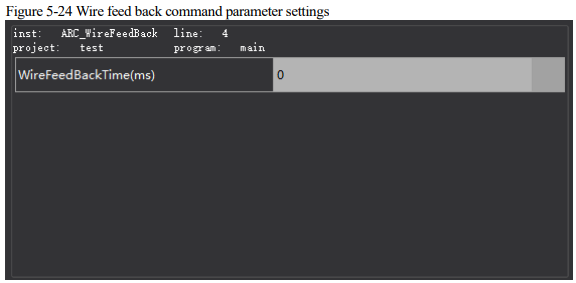
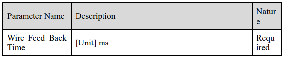
ARC_WireFeedBack
The wire feed back command, as shown in figure below
ARC_SlowWireSpeed
The slow wire feed command, as shown in figure below.
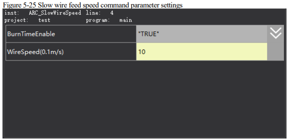
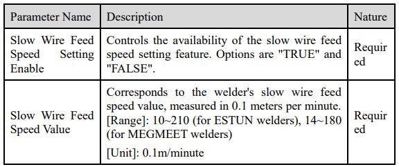
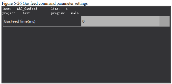
ARC_GasFeed
The gas feed command, as shown in figure below.

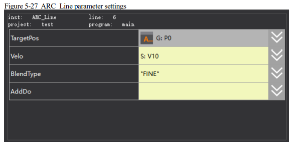
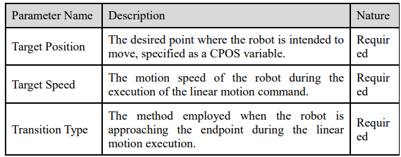
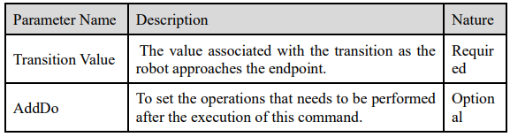
ARC_Line
The linear motion command, which enables the robot's Tool Center Point (TCP) end-effector to
move linearly to a target position at a constant speed. In the scenario where the TCP's orientation at
the starting point differs from that at the target point, the TCP's orientation will transition smoothly
from the starting orientation to the target orientation through continuous interpolation of
orientations during the linear motion from the starting position to the target position.
Unlike the MovL system command, the ARC_Line command specifies a target speed that remains
unaffected by the global speed percentage.
ARC_Circ
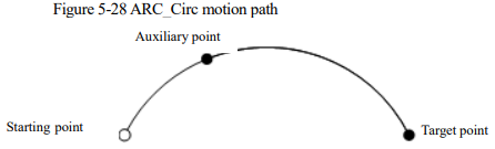
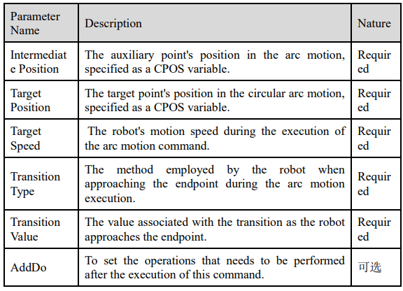
The circular motion command, which enables the robot's TCP end-effector to execute an arc motion, moving from the starting point through an auxiliary point to the target point, as shown in figure below.
The following rules must be observed when using this command:
⚫ For the robot's TCP end-effector to perform a complete circular motion, two arc motion commands must be executed.
⚫ In the arc motion command, the starting position, auxiliary position, and target position must be clearly distinguishable.
[Caution]
The starting position corresponds to either the target position of the previous motion command or the current TCP position of the robot.
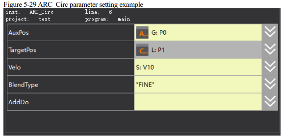
Differing from the system's native arc command, MovC, the ARC_Circ command allows specifying the target velocity value independent of the global speed setting. Refer to the diagram below, where P0 represents the auxiliary point in the robot's arc motion, and P1 signifies the target point of the arc motion.
ARC_SegmentC
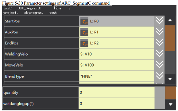
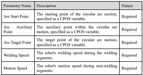
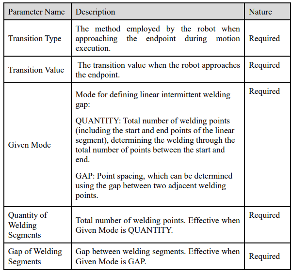
The command to invoke arc intermittent welding, as shown in figure below.
SetWeaveCFG
The command to invoke arc weave specification number, as shown in figure below.
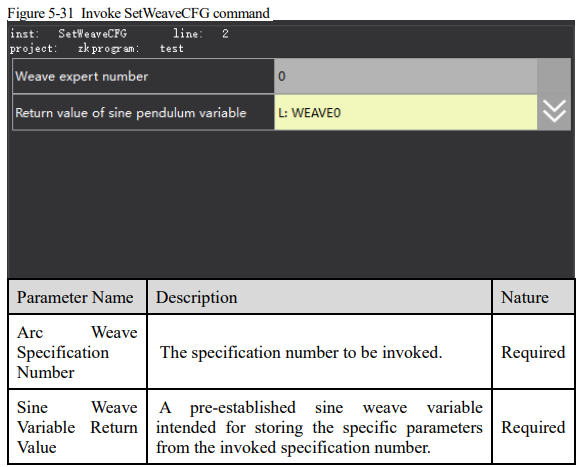
ARC_StichL
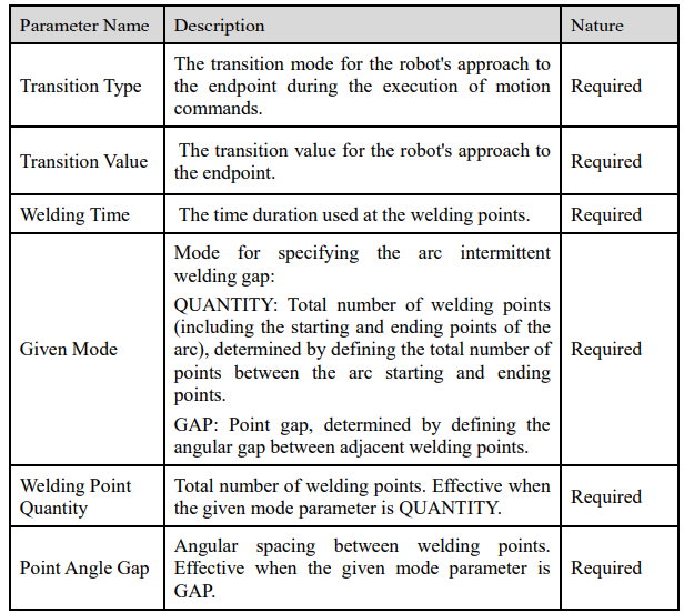
The linear intermittent spot welding command, which incorporates the arc striking and stopping commands, and does not need to add additional arc striking commands. To use this command, first teach the starting and ending points of the straight-line path. Next, select the welding mode between (QUANTITY and GAP, based on your requirements. Set the corresponding parameters depending on the chosen welding mode, including the number of welding points or the gap between points, along with the welding time. As shown in figure below.
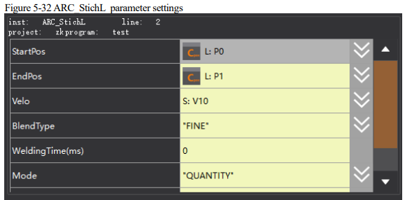
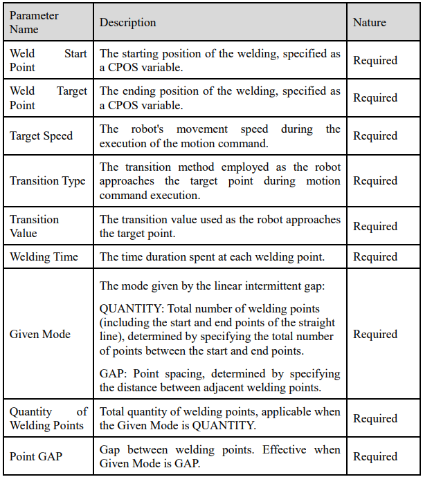
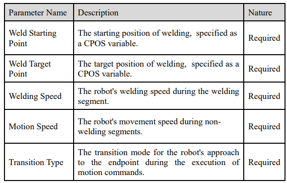
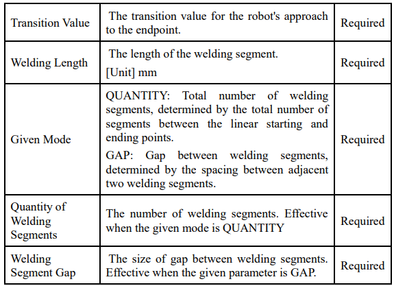
ARC_SegmentL
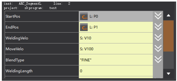
The linear segmented welding command. The proper use of this command requires the setup of
welding start and end points, the length of welding segments, the gap between welding segments, as well as the robotic welding and normal motion speed. The command is illustrated in Figure 3-14.
Segmented linear welding is applied in cases where there are gaps between welding segments along a straight bead welding path between the starting and target points. In practical applications, there are two variations: one involves specifying the number of welding segments, and the other involves specifying the welding gap.
When specifying the number of welding segments, the controller automatically calculates intermediate point information based on the linear length, welding length, and the desired number of welding segments. In this scenario, both ends of the line must be welded. When specifying the welding gap, the controller calculates intermediate point information based on the linear length, welding length, and welding gap, where the starting end of the straight path must be welded.
Whether the end is welded depends on the calculated results. This is illustrated in the figure below:

ARC_StichC
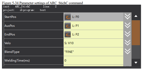
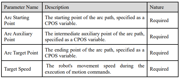
The arc intermittent spot welding command, which integrates the arc ON and arc OFF commands, and does not need to add additional striking and stopping commands. When using this command, first teach the transition point and endpoint of the arc; then, choose between the "QUANTITY" mode and the "Point GAP" mode. Set the corresponding parameters: the number of welding points or the angular spacing between welding points, along with the welding time. As shown in figure below.
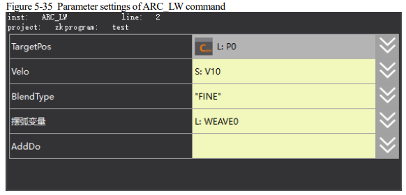
ARC_LW
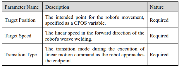
The linear welding weave command. Calling this command enables the welding path to follow a linear weave path.
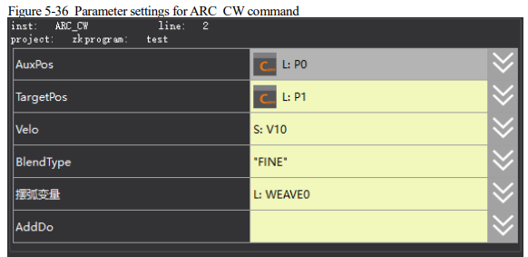
ARC_CW
The welding arc weave command. Calling this command enables the welding path to follow a arc weaving path, as shown in figure below.
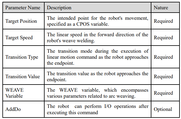
ARC_Fast
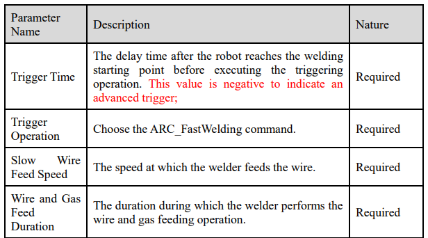
The fast arc striking command. When this command is invoked, the robot moves to the welding starting point within a certain time period. The welder initiates gas feeding, full wire feeding, and arc striking in advance, aimed at accelerating production takt. As shown in figure below.
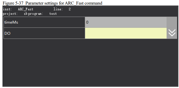
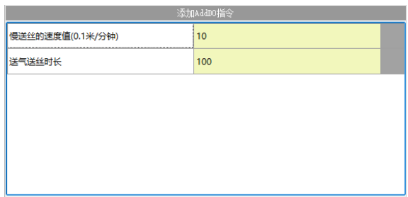
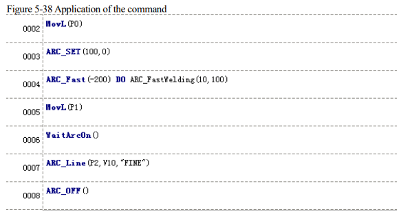
For instance, in the following program sequence, where P0 represents a safety point, P1 is the welding starting point, and P2 is the welding endpoint, the ARC_Fast command is inserted before the welding starting point P1. The robot moves to P1 200ms before reaching it, and the welder initiates gas feeding, full wire feeding, and arc striking.
WaitArcOn
The command used to wait for successful arc striking.
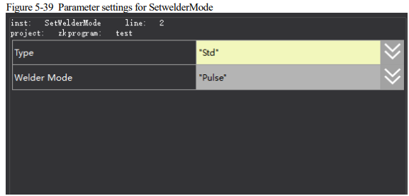
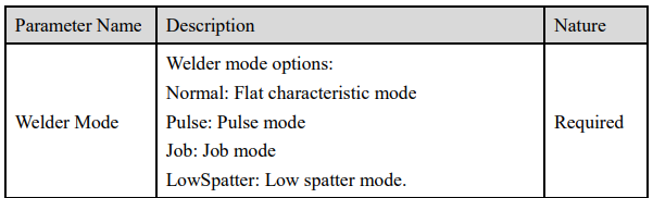
SetwelderMode
This command is used to set the welder working mode.
SetBlendParam
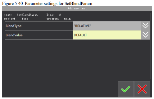
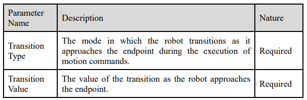
This command is used to set the transition parameters. The set transition parameters for this command take effect only when the default transition type for Arc_line and Arc_Circ commands is set to "FINE."
SetBurnTime
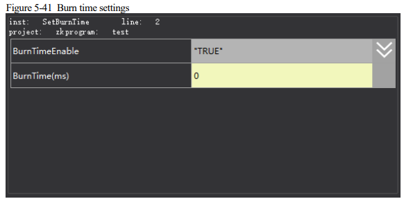
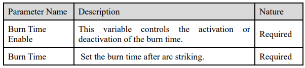
To set the burning parameters. This command allows enabling and setting the burn time.
ARC_Count
The command for welded workpiece counting. This command is used to tally completed welding workpiece information.
This command must be effective in automatic or remote mode, and with welding enabled.
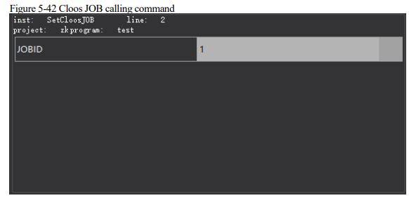
Cloos JOB Calling Command: SetCloosJOB
The command for calling a Cloos JOB.

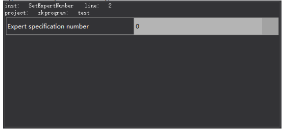
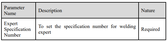
SetExpertNumber
5.1.3 Origin detection command
The origin detection functionality is a reserved feature and is not available in this version.
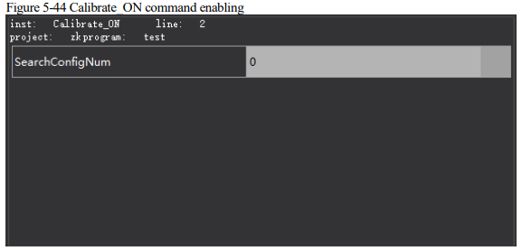
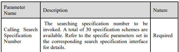
Calibrate_ON
The origin detection functionality calibration command, as shown in figure below.
Calibrate_OFF
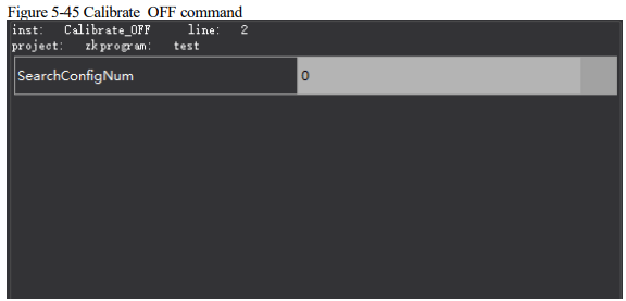
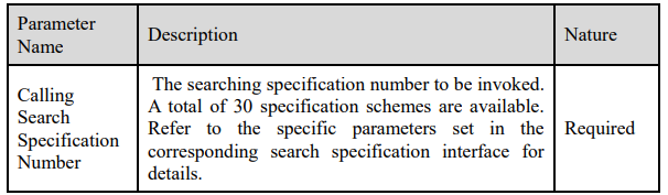
The origin detection functionality calibration OFF enable command, as shown in figure below.
Search_ON
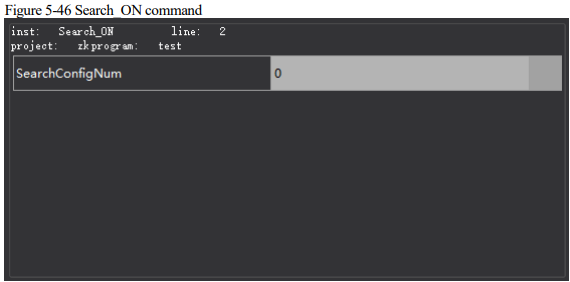
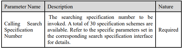
The origin detection searching enable command, as shown in figure below.
Search_OFF
The origin detection searching OFF enabling command, as shown in figure below
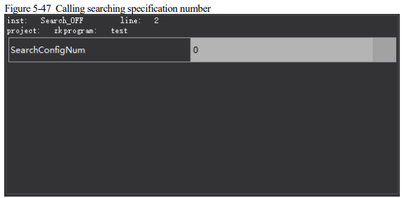
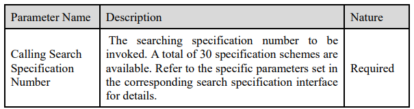
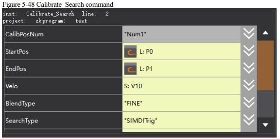
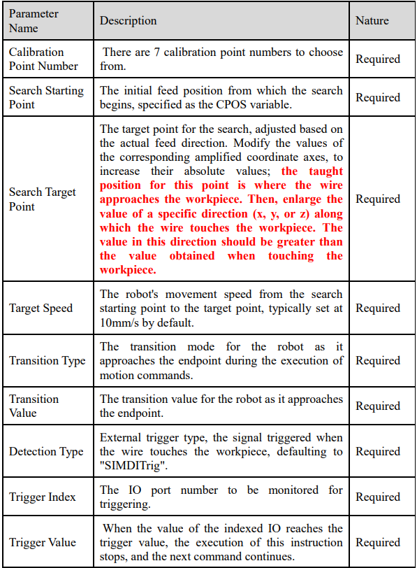
Calibrate_Search
The origin detection functionality calibration command, as shown in figure below.
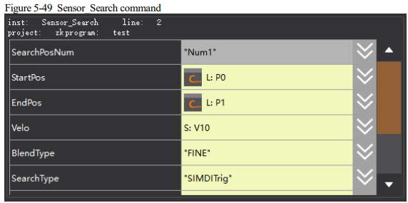
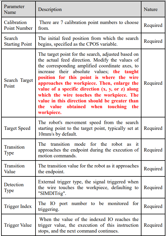
Sensor_Search
The origin detection search command, as shown in figure below.
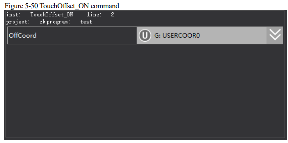
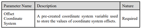
TouchOffset_ON
The command to enable coordinate system offset, as shown in figure below.
TouchOffset_OFF
The command to enable coordinate system offset OFF. This command has no parameters.
5.1.4 Line laser commands
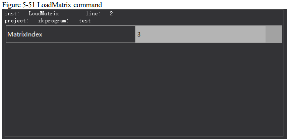
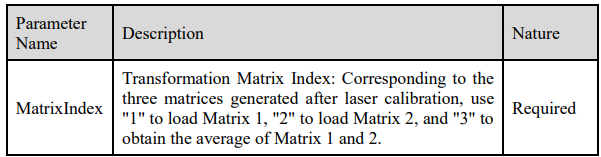
LoadMatrix
The command to load transformation matrix, as shown in figure below.
ConnectLaser
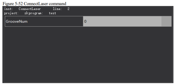
The command to connect to the laser, and to set bevel type, as shown in figure below.

DisConnectLaser
This command is used to disconnect from the laser. There’re no parameters for this command.
OpenLaser
Activate the laser beam.
CloseLaser
Deactivate the laser beam.
MuteLaser
Turn off the laser.
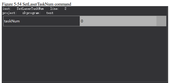
SetLaserTaskNum
Set the laser task number, as shown in the figure below.

Laser_Search
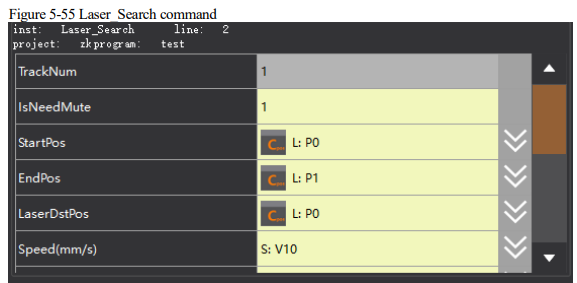
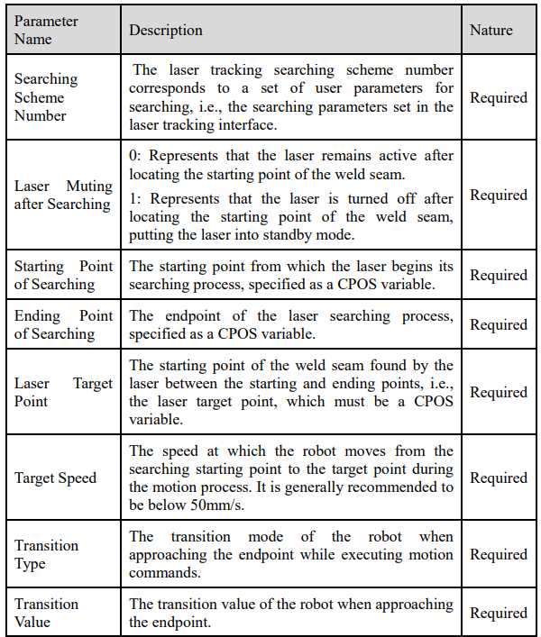
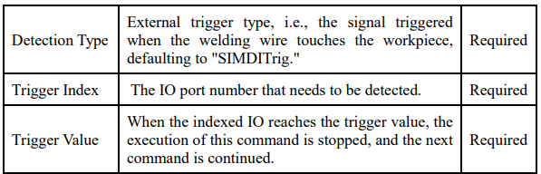
The laser search command, which is used to search the starting position of the weld seam using a laser, as shown in figure below
MovLTrack
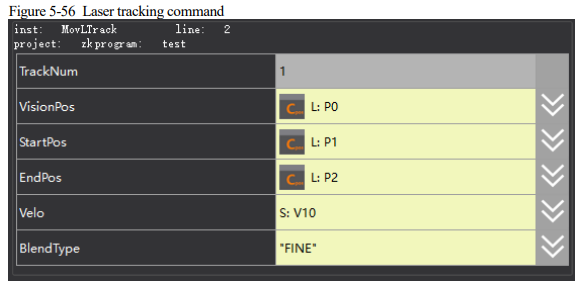
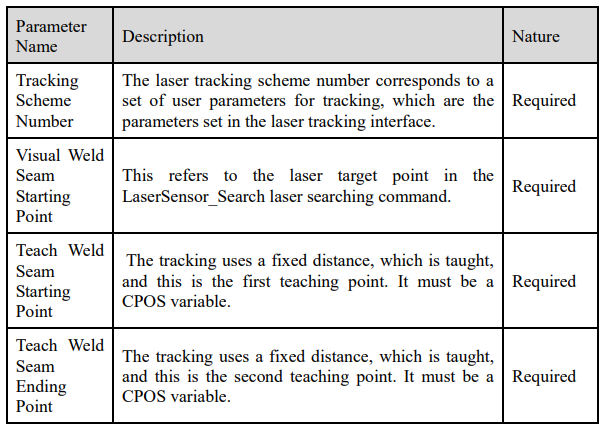
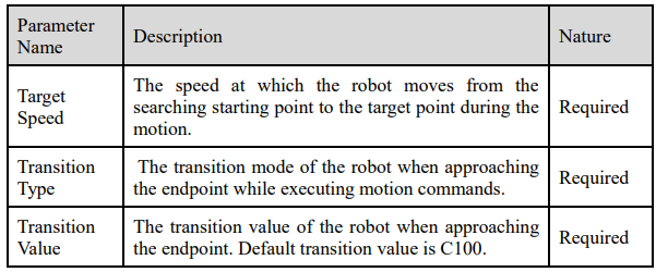
The laser tracking command. This command is used for laser scanning of the weld seam and transmitting the scanned points to the robot, enabling the robot to follow the weld seam's movement. It should be used in conjunction with the Laser_Search command. Additionally, this command integrates arc striking and arc stopping commands. If welding enablement is turned on, arc striking occurs at the starting point of the tracking command, and arc stopping occurs at the endpoint of tracking. Parameter descriptions are as shown in the figure below..
GetLaserPos
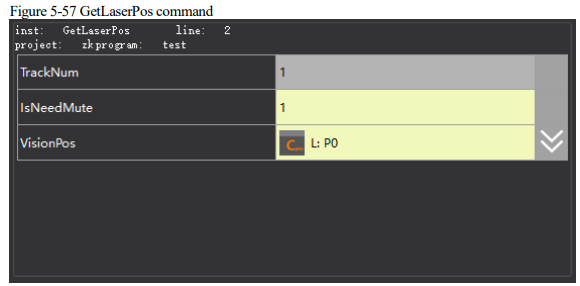
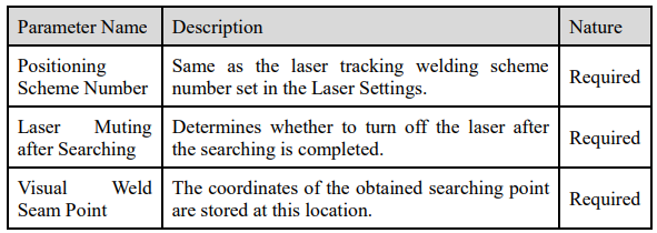
The command to get laser point position, as shown in the figure below.
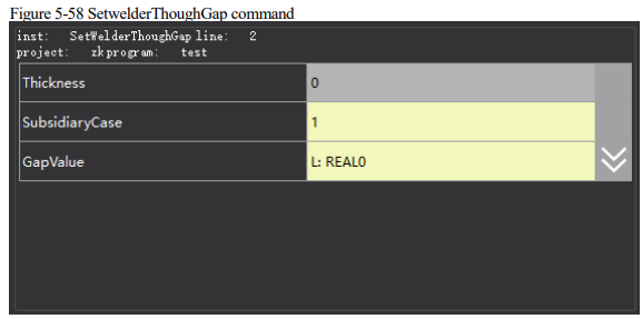
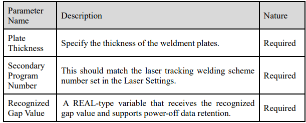
SetwelderThoughGap
The command to set welder through gap.
5.1.5 Control commands
Control commands are used to manage the path and execution of a program. They include commands that control program routes and states. Some of these commands are used in pairs to form code blocks. Here is a detailed explanation of several common control commands:
LABEL,GOTO,IF,ELSE,WHILE,CALL,RUN,KILL,RETURN,…=…,/*…*/. The following provides a detailed description:
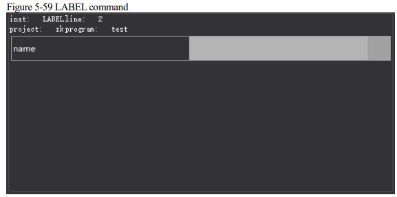
LABEL
Label command is used to define the jump target of GOTO.
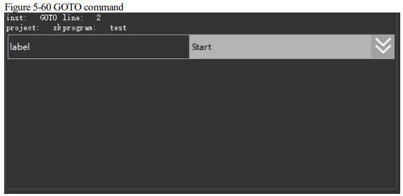
GOTO
GOTO command is used to jump to different parts of the program. The jump target is defined by the LABEL. It is not allowed to jump from the external into the internal program blocks. The internal block may be a WHILE cycle block or an IF block.
IF
IF command is used for jump control of the conditional judgment expression. When the result of the conditional judgment expression is TRUE, the program executes the block content under IF.
Similar to the IF statement in c++. The result of the IF condition judgment expression must be of BOOL type. For every IF command, any conditional judgment block must be ended with the
keyword ENDIF.
After selecting "Control Commands→ IF", you will enter the setting interface of IF statements, as shown in figure below.
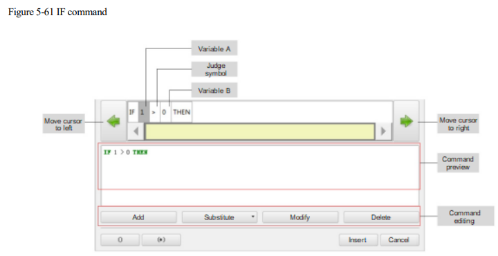
⚫ Variable A and Variable B can be set as constants or parameters: Click "Replace", and choose the constant, variable or function for replacement. To modify the value of a variable, you can move the cursor to the variable that needs to be modified, then click "Modify", and set the value in the pop-up dialog box.
⚫ The judgment symbol is used to judge the relationship between Variable A and Variable B. If it is TRUE, the command behind THEN is executed; if it is FALSE, the command behind THEN is skipped. To modify the judgement symbol, you can move the cursor to the judgement symbol, then click "Modify", and select the required symbol in the pop-up dialogue box.
⚫ Click "Add" to add a new "+" at the current position of the cursor, of which "+" denotes an operator, and "" denotes an operand.
◼ Click "+", then click "Modify" and select the desired operator in the pop-up soft keyboard, as shown in figure below.
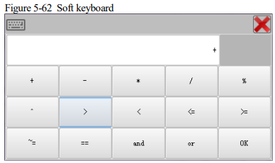 Click "", and then click "Replace" or "Modify" to change the operand to the desired constant, variable or function.
⚫ Click the operator or operand you would like to delete, and then click "Delete" to delete such operator and the subsequent operands.
⚫ Click an operator, and then click "()" to add a bracket to the operand in front of and behind the current operator. Click an operand and then click "()" to add a bracket to the current operand.
⚫ To delete the bracket, click the operator or operand, and then click "(*)" to delete the selected operator or operand response bracket.

[Note]
⚫ To delete an IF command, you need to click "Select Multi-line" in the program editing interface, then click the control statement between IF and END_IF, and then click "Edit → Delete" on the right menu.
⚫ When making replacement, you can select "mathematical function" or "character function". The functions are detailed in the Mathematical Operation Function and Character String Commands.
ELSEIF
⚫ ELSIF relies upon the IF command. It follows closely the IF command block. When the IF logic is not established, the ELSIF logic judgment is performed.
⚫ The way to set the ELSIF expression is the same as that of the IF expression.
⚫ Followings shall be noted when using this command:
⚫ ELSIF can be added behind the IF command block, but cannot be added separately.
⚫ ELSIF can also be added behind the ELSIF command block, of which one IF command block is followed by multiple ELSIF blocks.
⚫ ELSIF can be added in a nested way, which means that IF and ELSIF commands can be added in IF or ELSIF block.
⚫ After the IF logic is TRUE, the subsequent ELSIF commands will not be executed, but executing ENDIF directly.
⚫ After the IF logic is FALSE, the subsequent ELSIF commands will be executed; and if the ELSIF logic is FALSE, the subsequent ELSIF commands will then be executed.
⚫ After the IF logic is FALSE, the subsequent ELSIF command will be executed, and the ELSIF logic will be TRUE. The subsequent ELSIF commands will not, after execution, be executed, but executing ENDIF directly.
ELSE
ELSE command relies on the IF or ELSIF command. It is registered behind the IF or ELSIF block.
The statement will be executed when the IF or ELSIF condition judgment is not established.
WHILE
WHILE command executes sub-statements in loops when the conditions are met. The loop control expression must be of BOOL type. This command must end with the keyword ENDWHILE as the loop control.
The way to set WHILE expression is the same as that of IF expression.
For example:

This command executes the cyclic motion of 100 times between two points.
CALL
The CALL command. The current program jumps to another sub program in the same project, and jump back to the current program after the subroutine is executed. If the program to be called is program1, the command produced in the program is:

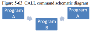
RUN
The program parallel running command. It enables the robot to run other programs while running the current program (the current program continues to run while starting another program without jumping) and the running program must be in the same project. If the program to be run is

[Note]
Currently, the controller supports 8 parallel running programs.
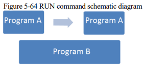
KILL
The command to stop parallel running. It enables the robot to stop running other programs while running the current program. The program stopped must be in the same project and in the running state. If the program that needs to be stopped is program1, the command produced in the program is:

RETURN
The RETURN command. In general, the program will jump to the end of the program after executing this command. If the RETURN is used in the CALL command, it will then return to the upper level program of the CALL command.
…=…
Establish an expression to assign a value to a variable, as shown in figure below.
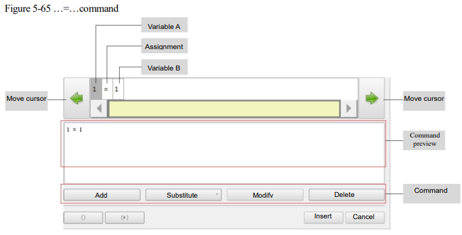
⚫ Variable A and Variable B can be set as constants or parameters: Click "Replace", and choose the constant, variable or function for replacement.
To modify the value of a variable, you can move the cursor to the variable that needs to be modified, then click "Modify", and set the value in the pop-up dialog box.
⚫ To add an assignment, move the cursor to "Variable B", and then click "Add", the expression will automatically add a new empty value, and the operator is "+" in default.
⚫ Click the operator "+", and then click "Modify" to select the desired operator.
⚫ Choose a new operator or subsequent variables, and then click "Delete" to delete the new operator and subsequent variables.
[Note]
When making replacement, you can select "mathematical function" or "character function". The functions are detailed in the Mathematical Operation Function and Character String Commands.
/*…*/
COMMENT command, to add definitions or remarks to the program.
This command will not affect the operation of the program, but only for reading and understanding the program.
5.1.6 SET commands
SetTool
Select the command of Tool Coordinates. Refer to the description in 2.6 Tool Coordinates for the way of tool coordinates settings. For example:

SetCoord
Select the command of User Coordinates. Refer to the description in the User Coordinates for the
way of user coordinates settings. For example:

SetExternalTCP
It is used to set the reference coordinates of the system to external tool coordinates. After command
execution, the system will switch the reference coordinates to the external tool coordinates. The robot will then move relative to the external tool coordinates. For example:

SetPositioner
It is used to set the reference coordinates of the system to POSITIONER coordinates. After command execution, the system will switch the reference coordinates to the POSITIONER coordinates. The robot will then move relative to the POSITIONER coordinates. For example:

[Note]
POSITIONER0 is of a positioner variable. The content in "POSITIONER data type" gives a detailed description.
SetJointDyn
It is used to set dynamic joint parameters, including Acceleration, Deceleration, Jerk, and Torque.
After running the command, the subsequent motion commands will all run using such dynamic parameters.
⚫ Acceleration: The percentage of the maximum acceleration of the joint.
⚫ Deceleration: The percentage of joint maximum deceleration.
⚫ Jerk: The percentage of the maximum jerk of the joint.
⚫ Torque: The percentage of the maximum torque of the joint.

SetCartDyn
Set the dynamic parameters in Cartesian space. After running this command, the subsequent motion commands will run using this dynamic parameter.
⚫ Acceleration: The percentage of the maximum acceleration in linear motion.
⚫ Deceleration: The percentage of the maximum deceleration in linear motion.
⚫ Jerk: The percentage of the maximum jerk in linear motion.
⚫ Posture Acceleration: The percentage of the maximum rotating acceleration of the posture.
⚫ Posture Deceleration: The percentage of the maximum rotating deceleration of the posture.
⚫ Posture Jerk: The percentage of the maximum rotating jerk of the posture.
⚫ Torque: The percentage of the maximum torque of the joint

SetBlendParam
It is used to set the transition parameters. After running this command, subsequent motion commands are run with this transition parameter. The command parameters are detailed below:
⚫ BlendType
Data type: enum (FINE/RELATIVE/DEFAULT)
Parameter meaning: The transition mode of the robot when approaching the endpoint
FINE: No transition.
RELATIVE: Relative transition.
ABSOLUTE: Absolute transition.
⚫ BlendValue
Data type: ZONE
Parameter meaning: The transition value when the robot is approaching the end point.
