9. 3D
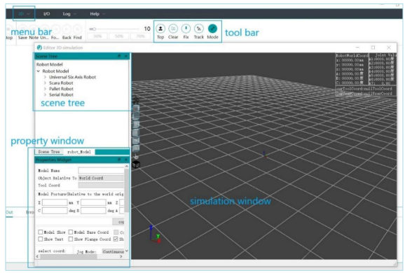
The 3D simulation includes the 3D menu, toolbar, property window, scene tree, and simulation window.
Left-click to rotate the scene, middle-click to pan the scene, and scroll the mouse wheel to zoom in or out.
9.1.Open the 3D Simulation Window
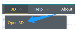
Click on "Open 3D Window" to load the 3D simulation window.
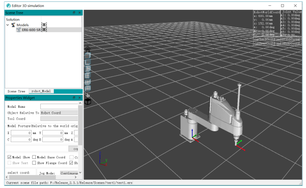
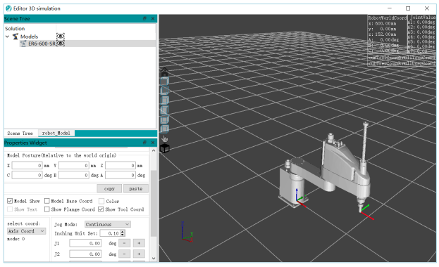
Note: The window data in the top right corner shows the robot's world coordinate system, which is the data relative to the center point of the robot's base surface.
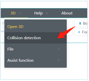
Click on "Collision Detection" to open the collision detection point list window. Further details on the collision detection module will be explained later.
9.2.1.New Scene
(1) Prerequisite: If you only want to view the motion of a single robot without any scene, there is no need to create a new scene. However, if you want to include other models, you need to create a new scene. You can use the shortcut key CTRL+O.
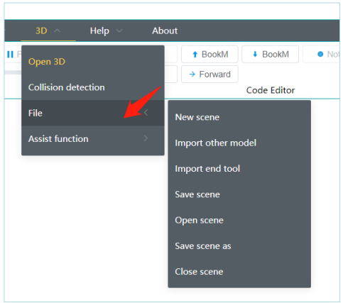
(2) Click on the 3D menu -> Click on File -> Click on Create Scene to create a new scene, which includes creating a scene space and a scene file (or use shortcut key Crtl+N).
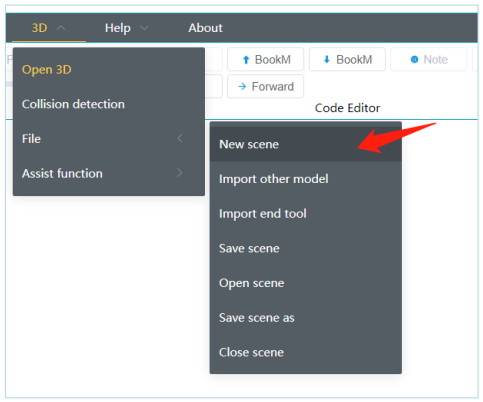
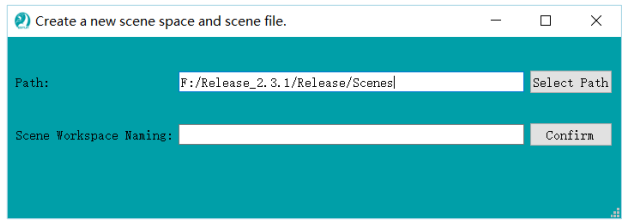
(3) Right-click on an empty space in the 3D simulation page and choose "Create Scene".
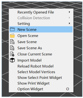
9.2.2.Import Other Models
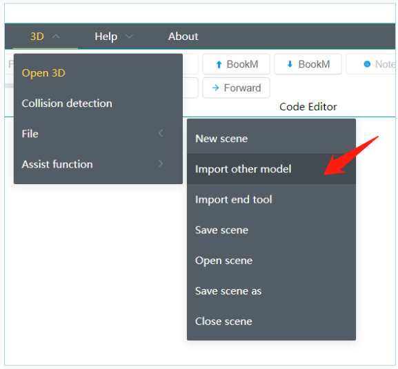
(1) Click on the 3D menu -> Click on File -> Click on Import Other Models to import models other than the robot model and robot tool model.
(2) Right-click on an empty space in the 3D simulation page and choose "Import Other Models".
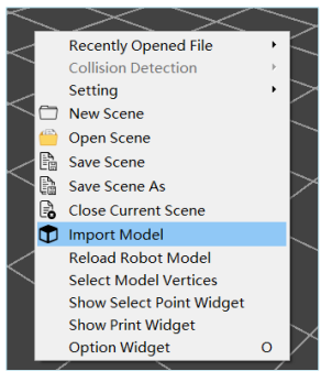
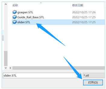
Note: Currently, the supported model format is .stl format. Please ensure that the size does not exceed 150MB. If the size exceeds 150MB, it may affect the smoothness of the display.
9.2.3.Import End Effector Tool Model
(1) Click on the 3D menu -> Click on File -> Click on End Effector Tool Model to import the model of the robot's tool.
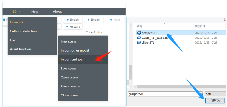
Note: Currently, the supported model format is .stl format. Please ensure that the size does not exceed 150MB. If the size exceeds 150MB, it may affect the smoothness of the display.
9.2.4.Save Scene
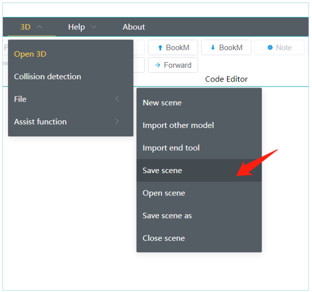
(1) Click on the 3D menu -> Click on File -> Click on Save Scene to save the current scene (Shortcut key (CTRL+S)) .
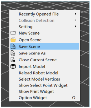
(2) Right-click on an empty space in the 3D simulation page and choose "Save Scene".
9.2.5.Open Scene
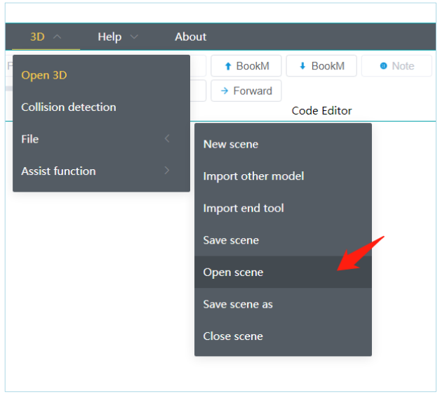
(1) Click on the 3D menu -> Click on File -> Click on Open Scene to open a 3D scene file (Shortcut key (CTRL+O)).
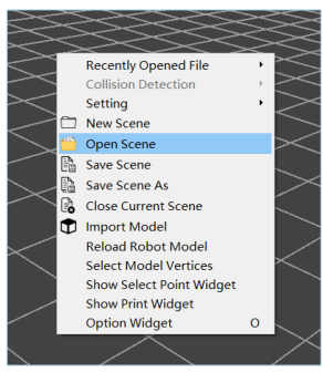
(2) Right-click on an empty space in the 3D simulation page and choose "Open Scene".
9.2.6.Save Scene As
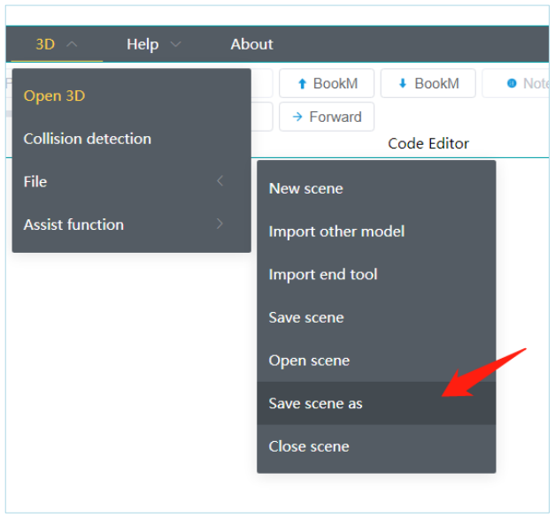
(1) Click on the 3D menu -> Click on File -> Click on Save Scene As to save the scene workspace files to a different folder
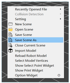
(2) Right-click on an empty space in the 3D simulation page and choose "Save Scene As".
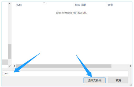
9.2.7.Close Scene
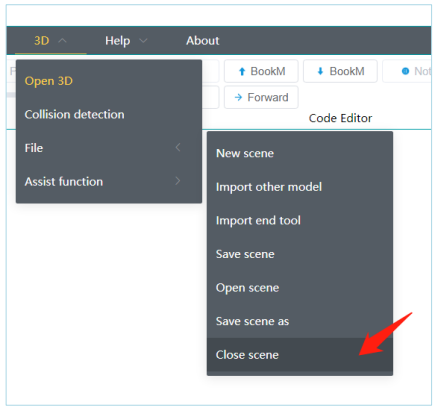
(1) Click on the 3D menu -> Click on File -> Click on Close Scene to close the currently opened scene.
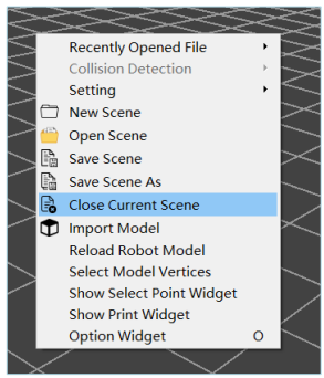
(2) Right-click on an empty space in the 3D simulation page and choose "Close Current Scene".
9.3. "Accessibility" Menu
9.3.1. Capture Screen
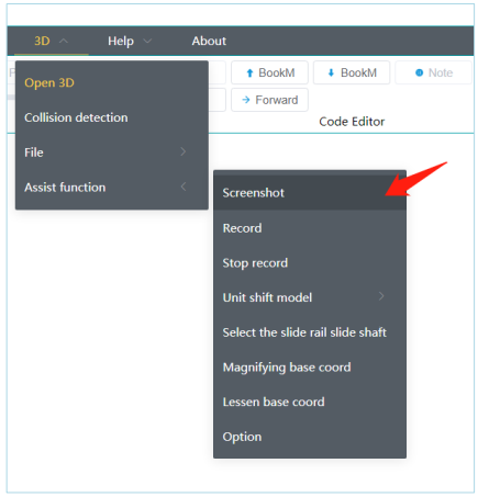
Click on the 3D menu -> Click on Accessibility -> Click on Capture Screen to save a screenshot of the current simulation page.
9.3.2.Record Screen
Click on the 3D menu -> Click on Accessibility -> Click on Record Screen to record a video of the current simulation page.
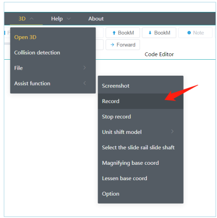
9.3.3.Stop Recording
Click on the 3D menu -> Click on Accessibility -> Click on Stop Recording to stop the current screen recording of the simulation page.
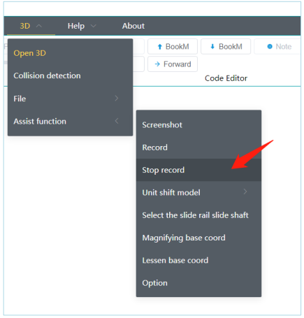
9.3.4.Unit Model Movement (ALT+1,2,3,4,5,6,7)
Click on the 3D menu -> Click on Accessibility -> Click on Unit Model Movement -> Choose XYZABC axis to move the model.
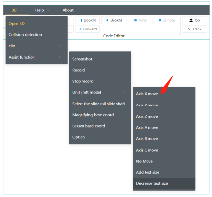
(1) Select X-axis: Corresponds to the translation axis X of the model. After selection, there will be text prompts in the scene. Press the UP arrow key on the keyboard to increase the value of the X-axis, and press the DOWN arrow key to decrease the value of the X-axis.(Shortcut key :ALT+1).
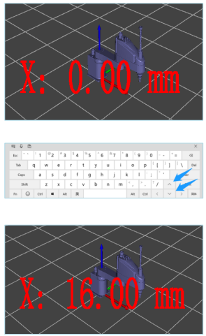
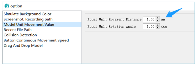
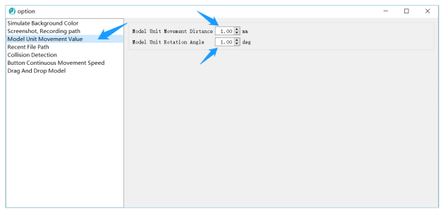
The default unit value added is 1, and you can set the unit movement length in the options.
(2) Select Y-axis: Corresponds to the translation axis Y of the model. After selection, there will be text prompts in the scene. Press UP arrow key on the keyboard to increase the value of the Y-axis ,and press the DOWN arrow key to decrease the value of the Y-axis(Shortcut key : ALT+2).
(3) Select Z-axis: Corresponds to the translation axis Z of the model. After selection, there will be text prompts in the scene. Press UP arrow key on the keyboard to increase the value of the Z-axis ,and press the DOWN arrow key to decrease the value of the Z-axis(Shortcut key : ALT+3).
(4) Select A-axis: Corresponds to the rotation axis A of the model. After selection, there will be text prompts in the scene. Press UP arrow key on the keyboard to increase the value of the A-axis, and press the DOWN arrow key to decrease the value of the A-axis(Shortcut key : ALT+4).
(5) Select B-axis: Corresponds to the rotation axis B of the model. After selection, there will be text prompts in the scene. Press up arrow key on the keyboard to increase the value of the B-axis, and press the DOWN arrow key to decrease the value of the B-axis (Shortcut key : ALT+5).
(6) Select C-axis: Corresponds to the rotation axis C of the model. After selection, there will be text prompts in the scene. Press UP arrow key on the keyboard to increase the value of the C-axis, and press the DOWN arrow key to decrease the value of the C-axis (Shortcut key: ALT+6).
(7) Select "No Movement" axis: Cancel the movement axis of the model (Shortcut key: ALT+7).
(8) Click on "Increase Text Size": Enlarges the text of the model's movement axis (Shortcut key: ALT+E).
(9) Select "Decrease Text Size": Reduces the text size of the model's movement axis (Shortcut key: ALT+R).
9.3.5.Select Slider Axis
Click on the 3D menu -> Click on Accessibility -> Click on Slider Axis
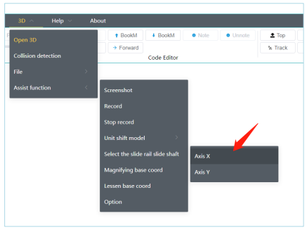
(1) Selecting the X-axis means that both the slider and the slider robot will move in the X-axis direction of the simulation world coordinate system.
(2) Selecting the Y-axis means that both the slider and the slider robot will move in the Y-axis direction of the simulation world coordinate system.
9.3.6.Zoom In Base Coordinates
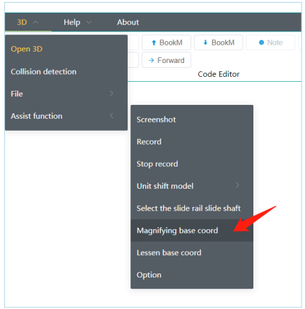
Click on the 3D menu -> Click on Accessibility -> Click on Zoom In Base Coordinates to zoom in on the base coordinates of the current model (Shortcut key: Page Up).
9.3.7.Zoom Out Base Coordinates
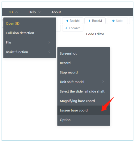
Click on the 3D menu -> Click on Accessibility -> Click on Zoom Out Base Coordinates to zoom out of the base coordinates of the current model (Shortcut key: Page Down).
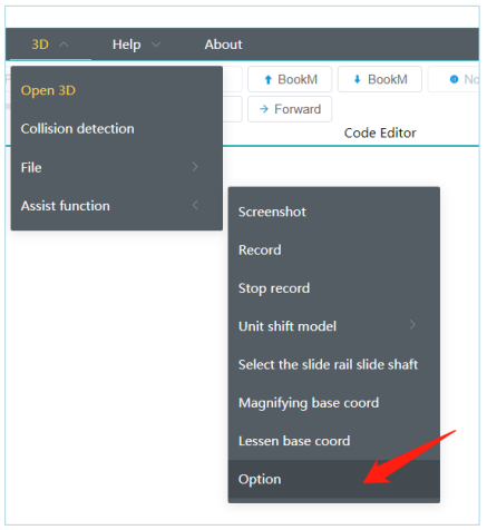
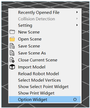
9.3.8.Options
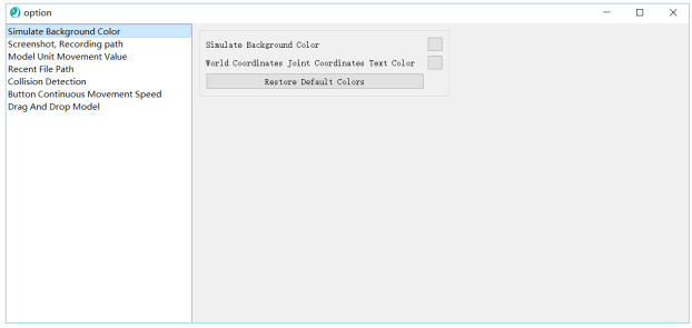
(1) Set simulation background color and text color in the data window.
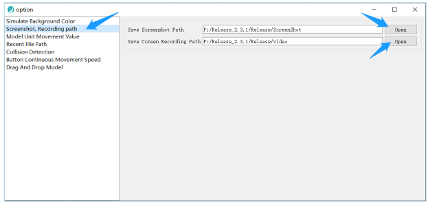
(2) Open the folder for saving screenshots and recorded screens.
(3) Set the value for unit movement of the model
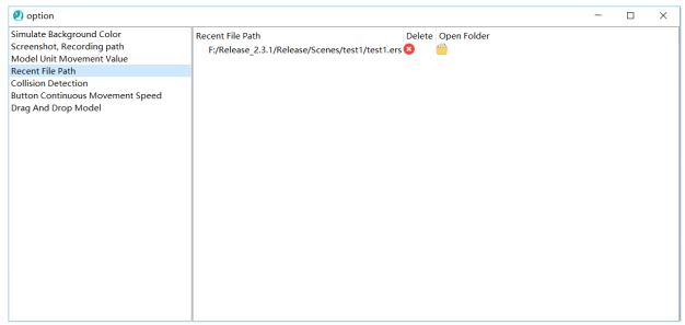
(4) Recent file paths, Manage the recently opened file paths. Click  to delete a file path record, and click
 to open the folder of this path.
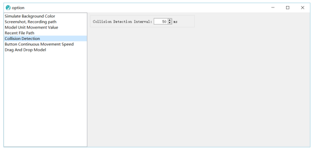
(5) Collision Detection,Set this parameter to adjust the time interval for collecting collision points in collision detection.
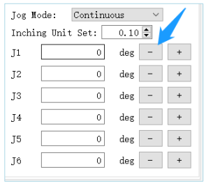
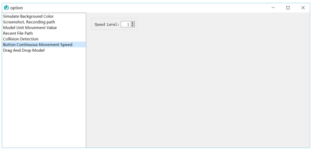
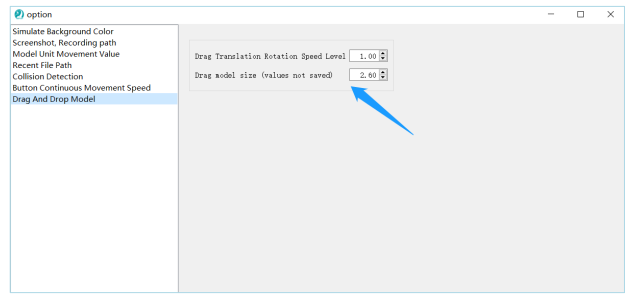
(7) Dragging Model,Set the speed of dragging the model and the size of the coordinate system for dragging the model.
9.4.Toolbar
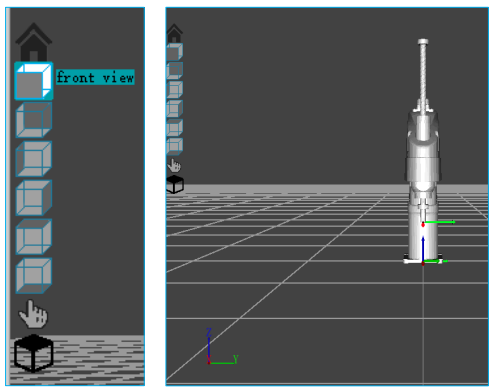
9.4.1.Front View
To set the front view of simulation window.
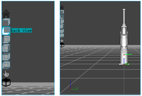
9.4.2.Back View
To set the rear view of simulation window.
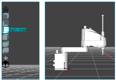
9.4.3.Left View
To set the left view of simulation window
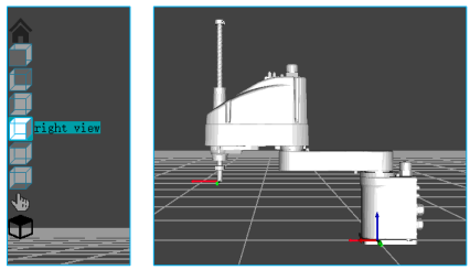
9.4.4.Right View
To set the right view of simulation window.
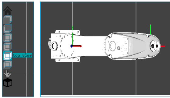
9.4.5.Top View
To set the top view of simulation window
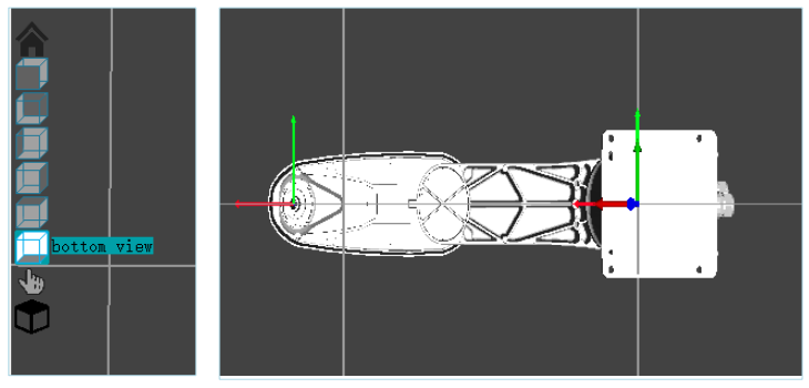
9.4.6.Bottom View
To set the bottom view of simulation window.
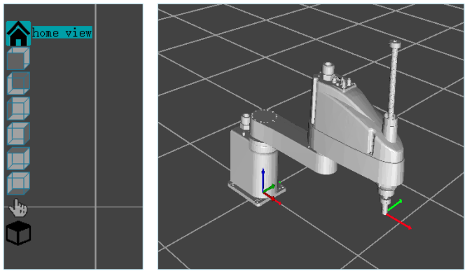
9.4.7.Restore View
To set the restore view of simulation window.
9.4.8.Path
To set the path of simulation window
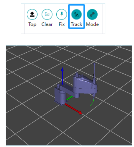
Note: This path is relative to the center point of the robot base. Therefore, in the case of a 7th-axis slider simulation, the displayed path is only for the robot and does not include the path of the slider.
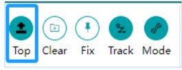
9.4.9.Always On Top
To set the simulation window to be always on top
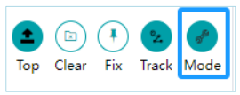
9.4.10.Modes
Opens or closes the scene tree and property window in the simulation window.