3. EtherCAT communication
3.1 CANopen over EtherCAT model
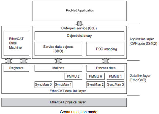
EtherCAT (CoE) network model is composed of two parts: data link layer and application layer. Data link layer is mainly in charge of EtherCAT communication protocol. Application layer is mainly oriented to CANOpen drive profiles (DS402) communication protocol. Object dictionary in CoE includes parameters, application data and PDO mapping information.
Process data object (PDO) is composed of objects in the object dictionary that could operate PDO mapping. The content of PDO data is defined by PDO mapping. PDO data’s read and write are periodical without checking OD. However, mail communication (SDO) is not periodic. When they are read or written, it is necessary to check OD.
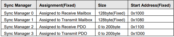
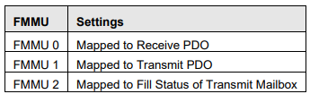
Note: To decode SDO data and PDO data on EtherCAT data link layer correctly, FMMU and Sync Manager have to configure as follows
Sync Manager Configuration
FMMU Settings
3.2 EtherCAT slave information
EtherCAT slave information (XML document) could be read by the master to build the master-slave configuration. ESTUN ProNet servo drive offers document as below
ESTUN_ProNet_V***.xml
*** is version number. The latest version is ESTUN_ProNet_V206.xml.
3.3 EtherCAT network state machine
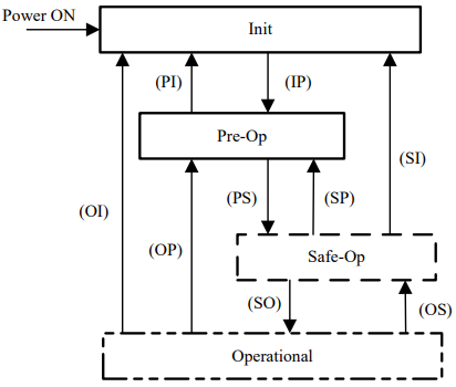
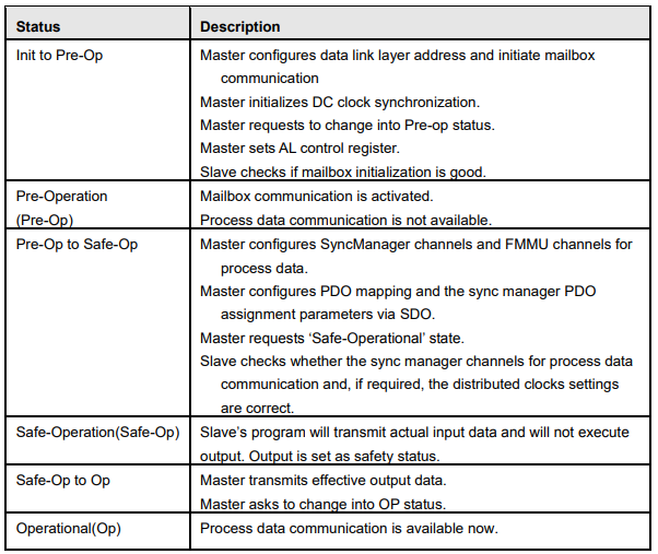
EtherCAT state machine is used to describe the states that one slave applies and the state change. State change request is normally launched by the master and answered by the slave. The graph below describes the slave’s state machine.

3.4 PDO mapping
Process data of EtherCAT slaves is composed by SyncMangaer channels. Each SyncMangaer channel describes the consistent area of process data. EtherCAT slaves with application control function should support PDO mapping and SM-PDO-Assign object reading.
PDO mapping
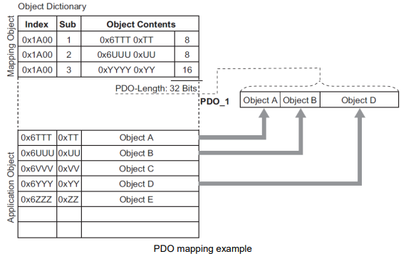
PDO mapping is related to the mapping from object dictionary to PDO’s application objects (real time process data). The index 0x1600 and 0x1A00 in object dictionary are separately reserved for the mapping tables of RXPDO and TxPDOs. The graph as below is one example. Each PDO mapping can add 10 objects at most, and total number of the bytes is 32 at most.
PDO configuration
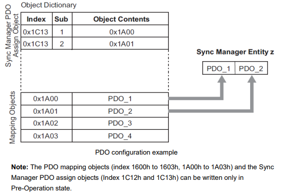
Sync manager object (SMCO) is composed of multiple PDOs. SM-PDO-Assign object (0x1C12 and 0x1C13) describes the relationship between PDOs and Sync Manager as below
PDO mapping process
Stop PDO allocating function (set the sub-index 0 of 0x1c12 and 0x1c13 into 0).
Stop PDO mapping function (set sub-index 0 of 0x1600~0x1603 and 0x1A00~0x1A03 into 0).
Set the number of mapping entries in PDO mapping objects (Set sub-index 0 of object 0x1600h to 0x1603h/0x1A00h to 0x1A03h).
Set the assignment of the Sync manager and PDO (Set sub index 1 of object 0x1C12h and 0x1C13h)
Enable the assignment of the Sync manager and PDO (Set sub index 0 of object 0x1C12h and 0x1C13h to 1).
Over again open PDO assignment function (set the sub-index 0 of 0x1c12 and 0x1c13 into 1)
3.5 Emergency message
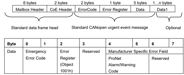
When the servo drive generates an alarm, Coe will activate an emergency message and inform consumers the current servo drive model number and error code.
Emergency message structure: