
5. CiA402 device protocol
ProNet’s device control is used mainly to achieve the motion control in different control modes. The master controls the servo drive through control word and knows the status of the servo drive by reading the servo drive’s status word.
5.1 CANopen over EtherCAT(CoE) state machine
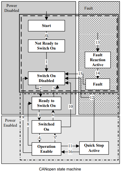
As above, the state machines could be divided into 3 parts: “power disabled”, “power enabled” and “fault”. All the states will be into “Fault” status after alarm. After power enabled, servo drive will finish initiating and then enter SWITECH_ON_DISA status. Now we could configure the servo drive, for example, set the working mode of the servo drive as profile position mode.
At this time, the main power supply is still shut down and the servo motor is now excitated. After the state transition 2, 3 and 4, the servo drive will be in OPERATION ENABLE mode. At this time, the main power will be switched on and servo drive starts to control the servo motor according to the configured working mode. So, before this state, we must ensure the servo drive’s parameters are correct. State Transition 9 will be used to shut down the main power supply. Once alarm happens to the servo drive, the servo drive’s state will be in FAULT state.
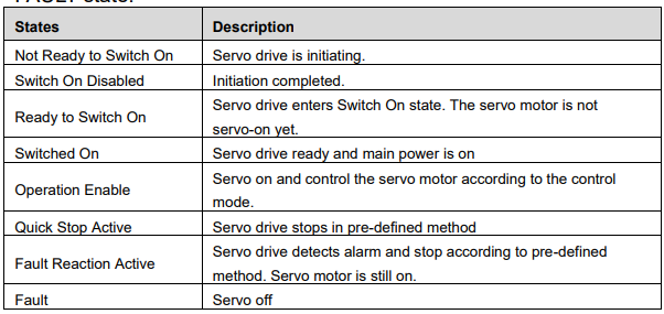
5.2 Parameters for device control
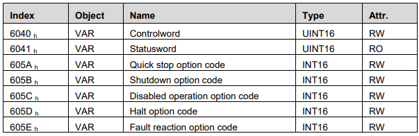
5.2.1 controlword
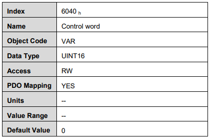
Control word bit description:

Bit0 ~ 3 and Bit7:
The transmission of state machine will be triggered by the command composed by these 5 bits.
Device control command list
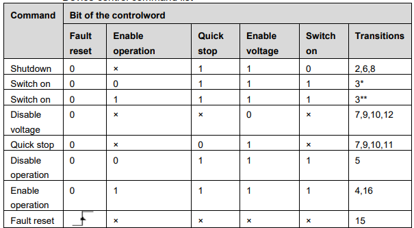
Note: X means this bit could be ignored.
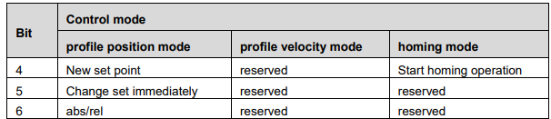
Bit4, 5, 6,:
In different control mode, these 3 bits’ definition will be different.
Bit8:
Halt. Set to 1 means servo motor stops according to the value of 605D.
The other bits: All reserved.
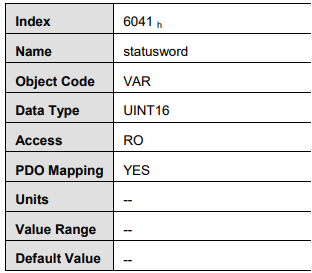
5.2.2 statusword
Statusword bit introduction is as below
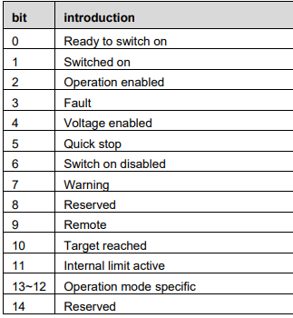
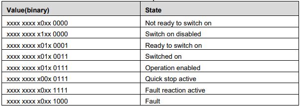
Bit0 ~ 3 , Bit5 and Bit6:
The combination of these bits represents the status of the servo drive
Bit4: Voltage enabled
When this bit is 1, it means the main power is on.
Bit5: Quick stop
When this bit is 0, it means the servo drive will stop the servo motor according to the configuration(605A h: quick_stop_option_code)
Bit7: Warning
When the bit is 1, it means the servo drive detects alarm.
Bit9: Remote
The bit always is 1 , it means Controlword can be deal with.
Bit10: Target reached
In different control mode, this bit has different meanings.
In PP/PV/PT/CSP/CSV/CST mode, when the set value is reached, this bit will be set as 1. When Halt is activated and speed decreases to zero, this bit will be set as 1. In HM mode, when homing is completed, this bit will be set as 1. When Halt is activated and speed decreases to zero, this bit will be set as 1.
Bit11: Internal limit active
When this bit is 1, it means that the internal torque has surpassed the set value, or machine has run into external positive /negative limit switch.
Bit12, 13:
These two bits in different control mode have different meaning.

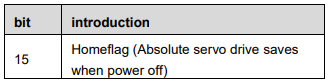
Bit15:Homeflag
When absolute servo drive Pn002.2 is 0,this bit is effective. When this bit is 1,it means homing is completed and save when power off.
The other bits: All reserved
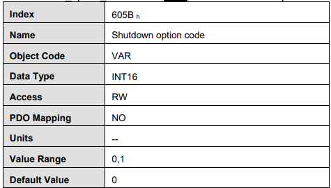
5.2.3 shutdown_option_code
When Operation Enable mode is transit to Ready to Switch On status,
Shutdown_option_code will be used to define how to stop the servo motor.

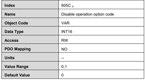
5.2.4 disable_operation_option_code
When the status of Operation Enable transits to Switched On status, disable_operation_option_code will decide how to halt.

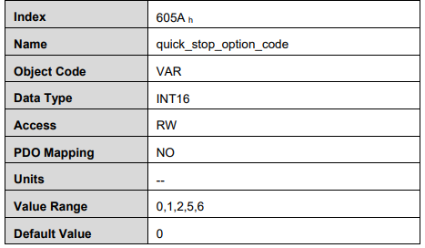
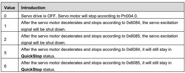
5.2.5 quick_stop_option_code
When the Operation Enable status transits to Quick Reaction Active status, quick_stop_option_code will define how to stop.
5.2.6 halt_option_code
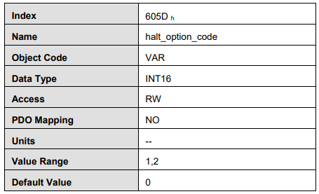
When bit8 of Controlword is 1, halt option code will define how to halt. .

5.2.7 fault_reaction_option_code
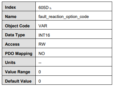
When it alarms, fault_reaction_option_code will decide how to halt. .

5.3 Control mode
ProNet servo drive supports 8 control modes:
Homing mode
Profile position mode
Profile velocity mode
Profile torque mode
Interpolated position mode
Cyclic synchronous position mode
Cyclic synchronous velocity mode (ProNet-□□□EG-EC only)
Cyclic synchronous torque mode
Touch probe function
Torque limit function
This chapter will mainly describe these 8 control methods as above.
5.4 Control mode parameters

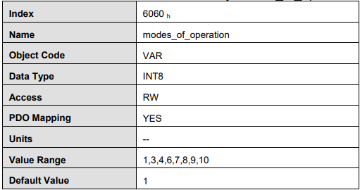
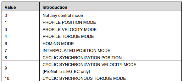
modes_of_operation
Servo drive’s control mode is defined by modes_of_operation.
modes_of_operation_display
Servo drive’s current control mode could be read from the modes_of_operation_display.
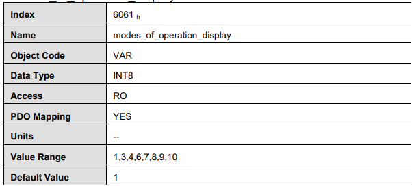
Note: Only through the parameters of modes_of_operation_display, we could get the control mode of the servo drive.
5.5 Homing mode
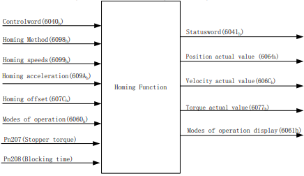
ProNet servo drive now supports multiple homing methods. Clients could choose the homing method that suits the motor type and application.
Clients can set homing method, homing speed and acceleration. After the servo drive finds the reference point, we could also set the distance between homing position and reference point as much as the value defined by home_offset (607C h).
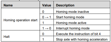
5.5.1 Control word

*: please refer to previous chapters
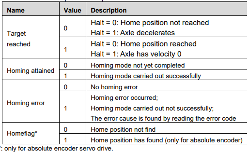
5.5.2 State word

*: Please refer to the previous chapters
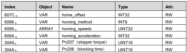
5.5.3 Parameters related to homing mode
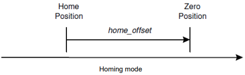
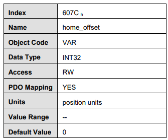
home_offset
Home_offset defines the distance between home position and zero position. If 607C is set to 0, the home position coincides in zero position. If 607C is not set to 0, the home position is mechanical home= mechanical zero +607Ch . When homing has completed, the value of actual position 0x6064 is the value of 607Ch(home_offset).
homing_method
There are 4 signals as homing signals: positive limit switch, neg