
5. CiA402 device protocol
ProNet’s device control is used mainly to achieve the motion control in different control modes. The master controls the servo drive through control word and knows the status of the servo drive by reading the servo drive’s status word.
5.1 CANopen over EtherCAT(CoE) state machine
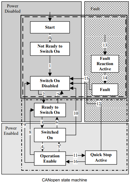
As above, the state machines could be divided into 3 parts: “power disabled”, “power enabled” and “fault”. All the states will be into “Fault” status after alarm. After power enabled, servo drive will finish initiating and then enter SWITECH_ON_DISA status. Now we could configure the servo drive, for example, set the working mode of the servo drive as profile position mode.
At this time, the main power supply is still shut down and the servo motor is now excitated. After the state transition 2, 3 and 4, the servo drive will be in OPERATION ENABLE mode. At this time, the main power will be switched on and servo drive starts to control the servo motor according to the configured working mode. So, before this state, we must ensure the servo drive’s parameters are correct. State Transition 9 will be used to shut down the main power supply. Once alarm happens to the servo drive, the servo drive’s state will be in FAULT state.
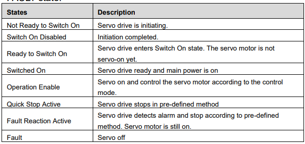
5.2 Parameters for device control
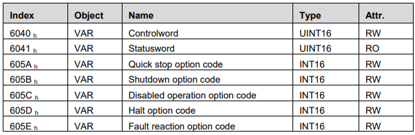
5.2.1 controlword
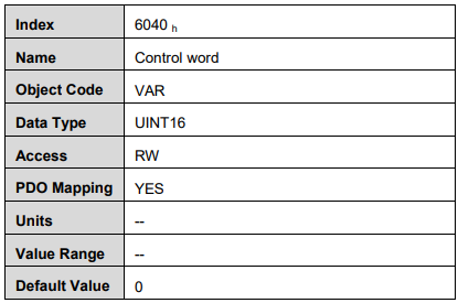
Control word bit description:

Bit0 ~ 3 and Bit7:
The transmission of state machine will be triggered by the command composed by these 5 bits.
Device control command list
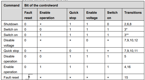
Note: X means this bit could be ignored.
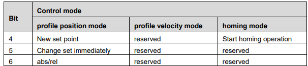
Bit4, 5, 6,:
In different control mode, these 3 bits’ definition will be different.
Bit8:
Halt. Set to 1 means servo motor stops according to the value of 605D.
The other bits: All reserved.
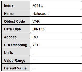
5.2.2 statusword
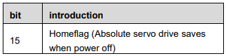
Statusword bit introduction is as below
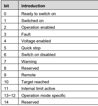
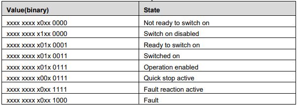
Bit0 ~ 3 , Bit5 and Bit6:
The combination of these bits represents the status of the servo drive
Bit4: Voltage enabled
When this bit is 1, it means the main power is on.
Bit5: Quick stop
When this bit is 0, it means the servo drive will stop the servo motor according to the configuration(605A h: quick_stop_option_code)
Bit7: Warning
When the bit is 1, it means the servo drive detects alarm.
Bit9: Remote
The bit always is 1 , it means Controlword can be deal with.
Bit10: Target reached
In different control mode, this bit has different meanings.
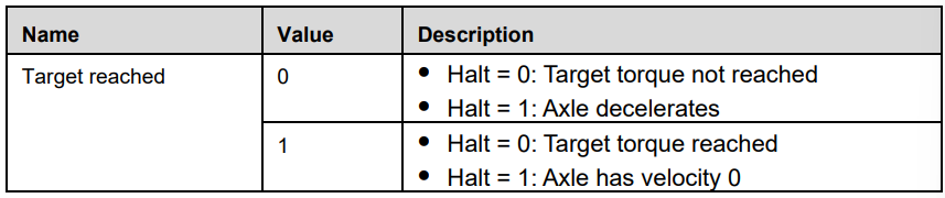
In PP/PV/PT/CSP/CSV/CST mode, when the set value is reached, this bit will be set as 1. When Halt is activated and speed decreases to zero, this bit will be set as 1. In HM mode, when homing is completed, this bit will be set as 1. When Halt is activated and speed decreases to zero, this bit will be set as 1.
Bit11: Internal limit active
When this bit is 1, it means that the internal torque has surpassed the set value, or machine has run into external positive /negative limit switch.
Bit12, 13:
These two bits in different control mode have different meaning.

Bit15:Homeflag
When absolute servo drive Pn002.2 is 0,this bit is effective. When this bit is 1,it means homing is completed and save when power off.
The other bits: All reserved
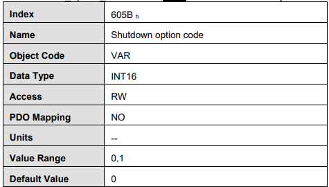
5.2.3 shutdown_option_code
When Operation Enable mode is transit to Ready to Switch On status,
Shutdown_option_code will be used to define how to stop the servo motor.

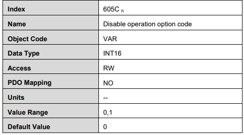
5.2.4 disable_operation_option_code
When the status of Operation Enable transits to Switched On status, disable_operation_option_code will decide how to halt.

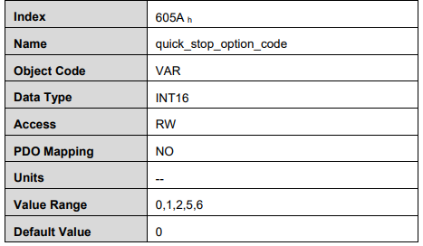
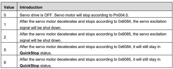
5.2.5 quick_stop_option_code
When the Operation Enable status transits to Quick Reaction Active status, quick_stop_option_code will define how to stop.
5.2.6 halt_option_code
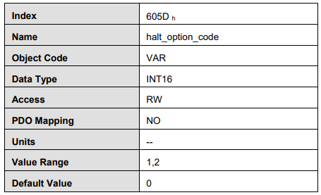
When bit8 of Controlword is 1, halt option code will define how to halt. .

5.2.7 fault_reaction_option_code
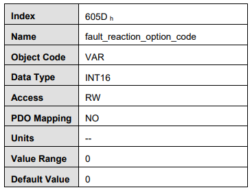
When it alarms, fault_reaction_option_code will decide how to halt. .

5.3 Control mode
ProNet servo drive supports 8 control modes:
Homing mode
Profile position mode
Profile velocity mode
Profile torque mode
Interpolated position mode
Cyclic synchronous position mode
Cyclic synchronous velocity mode (ProNet-□□□EG-EC only)
Cyclic synchronous torque mode
Touch probe function
Torque limit function
This chapter will mainly describe these 8 control methods as above.
5.4 Control mode parameters

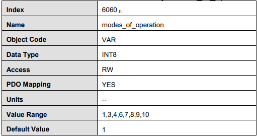
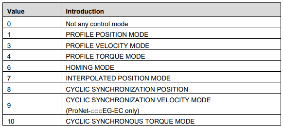
modes_of_operation
Servo drive’s control mode is defined by modes_of_operation.
modes_of_operation_display
Servo drive’s current control mode could be read from the modes_of_operation_display.
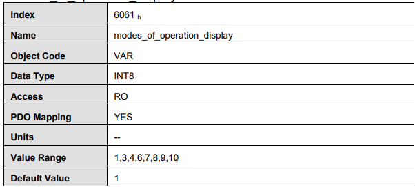
Note: Only through the parameters of modes_of_operation_display, we could get the control mode of the servo drive.
5.5 Homing mode
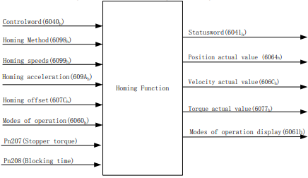
ProNet servo drive now supports multiple homing methods. Clients could choose the homing method that suits the motor type and application.
Clients can set homing method, homing speed and acceleration. After the servo drive finds the reference point, we could also set the distance between homing position and reference point as much as the value defined by home_offset (607C h).
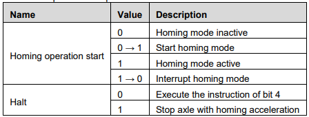
5.5.1 Control word

*: please refer to previous chapters
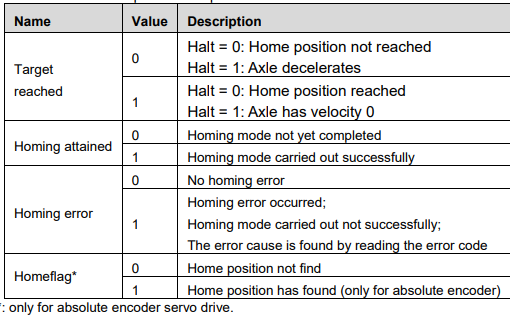
5.5.2 State word

*: Please refer to the previous chapters
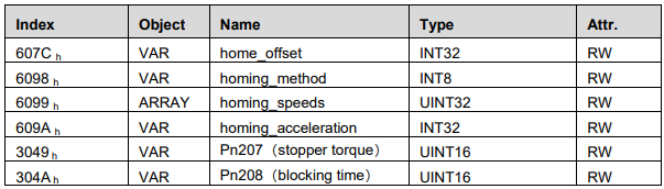
5.5.3 Parameters related to homing mode
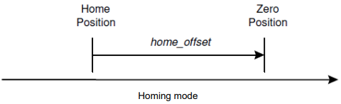
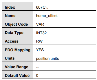
home_offset
Home_offset defines the distance between home position and zero position. If 607C is set to 0, the home position coincides in zero position. If 607C is not set to 0, the home position is mechanical home= mechanical zero +607Ch . When homing has completed, the value of actual position 0x6064 is the value of 607Ch(home_offset).
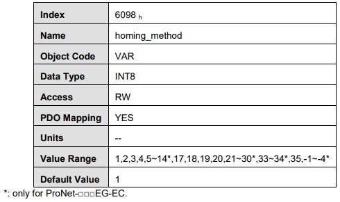
homing_method
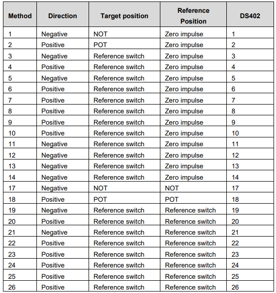
There are 4 signals as homing signals: positive limit switch, negnegative limit switch, reference switch and Zero impulse (C pulse).
homing method table
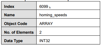
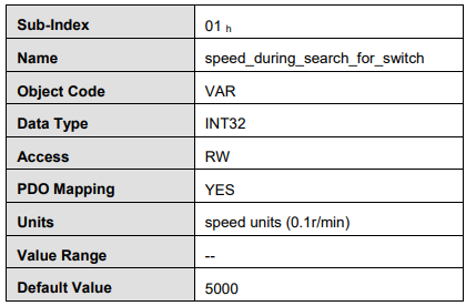
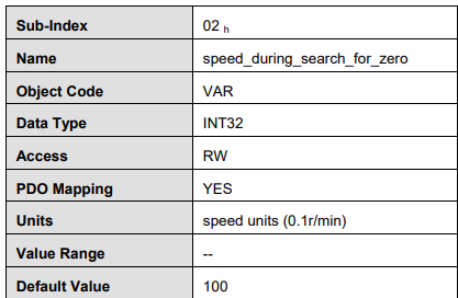
homing_speeds
Two kinds of speed are used in finding the reference position: The speed to find reference position and the speed to find zero position.
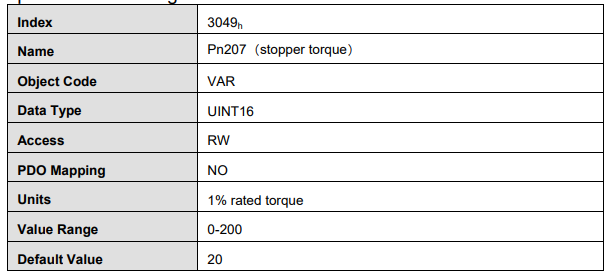
Pn207(stopper torque)
It is used for homing method -4、-3、-2、-1.When the drive hits an end so that the torque set in Pn207 is reached for the blocking time set in Pn208,movement in the opposite direction or makes the current position for the origin.
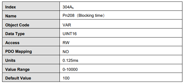
Pn208(blocking time)
It is used for homing method -4、-3、-2、-1.When the drive hits an end so that the torque set in Pn207 is reached for the blocking time set in Pn208,movement in the opposite direction or makes the current position for the origin.
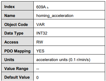
homing_acceleration
Acceleration and deceleration in homing are all defined by homing_acceleration.
5.5.4 Homing method
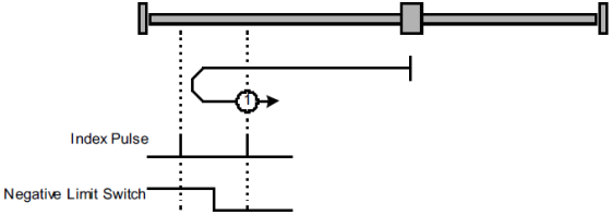
Homing method 1: Use C pulse and negative limit switch Servo drive needs to move at first toward negative direction fast till reaching the negative limit switch and then decelerate till stop. And then, servo motor will be bounced back slowly and find the target homing position. Under this homing method, the target homing position is the first C pulse away from the limit switch.
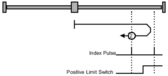
Homing method 2: Use C pulse and positive limit switch At first servo motor will move fast toward positive direction and decelerate to stop after reaching the positive limit switch. And then servo motor will be bounced back slowly to find homing position. Under this homing method, the target homing position is the first C pulse away from the limit switch.
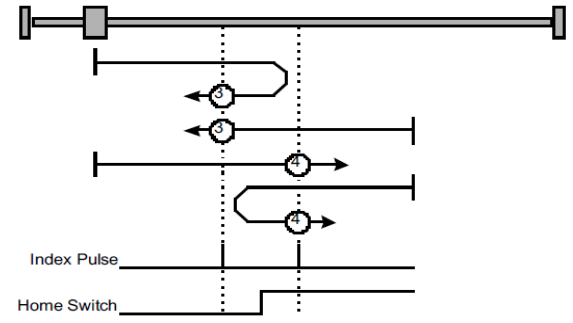
Homing method 3 and 4: Use C pulse and positive reference point limit switch
It is used that reference point limit switch is on positive direction and negative direction is zero. That is on the end of movement positive direction. Servo drive’s initial moving direction is relied on the status of reference point limit switch. The target homing position is on the left side or right side of the reference limit switch. The distance between the reference position switch and homing position is one C pulse.
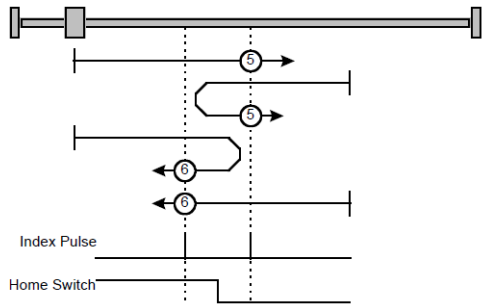
Homing method 5 and 6: Use C pulse and negative reference point limit switch
It is used that reference point limit switch is on negative direction and positive direction is zero. That is on the edge of movement negative direction. Servo drive’s initial moving direction is relied on the status of reference point limit switch. The target homing position is on the left side or right side of the reference limit switch. The distance between the reference position switch and homing position is one C pulse.
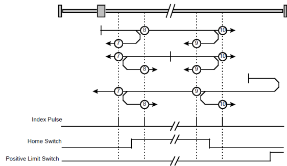
Homing method 7~10: Use C pulse,reference point limit switch and positive limit switch
It is used that reference point limit switch is in the middle. And homing is according to C pulse,reference point limit switch and positive limit switch. The final mechanical point is the position of C pulse.
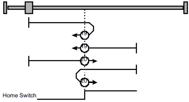
Homing method 17 ~ 30:Not use C pulse
Homing methods 17~30 are similar to method 1~14, but the target homing position is
not relied on C pulse any more but on the change of limit switch or reference point.
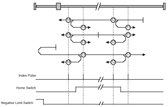
For example, as below, method 19 and method 20 are just similar to method 3 and
method 4. : Use C pulse,reference point limit switch and negative limit switch
It is used that reference point limit switch is in the middle. And homing is according to C pulse,reference point limit switch and negative limit switch. The final mechanical point is the position of C pulse.
Homing method 17 ~ 30:Not use C pulse
Homing methods 17~30 are similar to method 1~14, but the target homing position is not relied on C pulse any more but on the change of limit switch or reference point. For example, as below, method 19 and method 20 are just similar to method 3 and method 4.
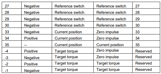
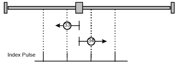
Homing method 33 and 34:Homing on the position on reaching C pulse from current position
Homing method 33:The drive moves slowly into the negative direction,stops until reaches C pulse. Homing method 34 is similar to method 34.
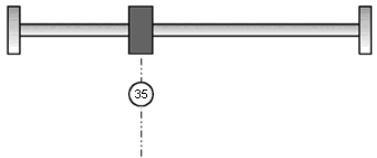
Homing method 35: Homing on the current position
In this method, the current position shall be taken to be the home position
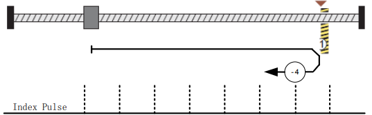
Homing method -4 Movement in positive direction, hitting an end and reversing to travel,the target homing position is the first C pulse
In this method, the motor moves in positive direction. When it hits an end so that the torque set in Pn207 is reached for the blocking time set in Pn208,movement in the opposite direction, and the target homing position is the first C pulse.
Homing method -3 Movement in negative direction, hitting an end and reversing to travel,the target homing position is the first C pulse
In this method, the motor moves in negative direction. When it hits an end so that the torque set in Pn207 is reached for the blocking time set in Pn208,movement in the opposite direction, and the target homing position is the first C pulse.
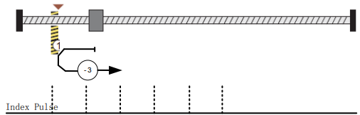
Homing method -2:Movement in positive direction, hitting an end, makes the current position for the origin.
In this method, the motor moves in positive direction. When the drive hits an end so that the torque set in Pn207 is reached for the blocking time set in Pn208,and makes the current position for the origin.

Homing method -1:Movement in negative direction, hitting an end, makes the current position for the origin.
In this method, the motor moves in negative direction. When the drive hits an end so that the torque set in Pn207 is reached for the blocking time set in Pn208,and makes the current position for the origin.

5.6 Profile velocity mode
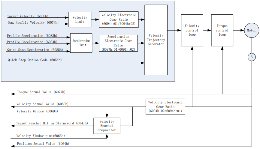
In the profile velocity mode, the speed is output in accordance with the acceleration and deceleration, until it reaches the target velocity.
The following figure shows the block diagram of the profile velocity mode.
5.6.1 Control word


5.6.2 State word


5.6.3 Parameters related to velocity mode
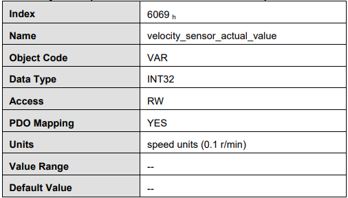
velocity_sensor_actual_value
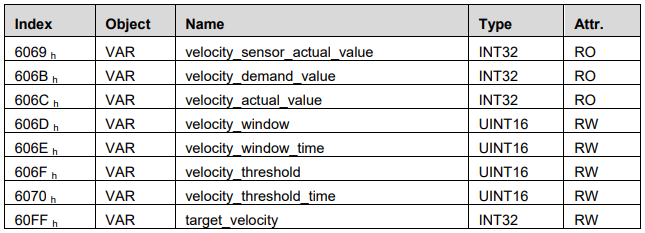
The master could read velocity_sensor_actual_value to know the current velocity. The parameter’s unit is internal speed unit.
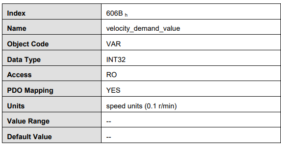
velocity_demand_value
Master can read velocity_demand_value to know the current reference speed value of the servo drive. The unit of this parameter is user’s velocity unit.
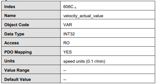
velocity_actual_value
The master can read velocity_ actual _value to know the current velocity of the servo motor. The unit of this parameter is user’s velocity unit.
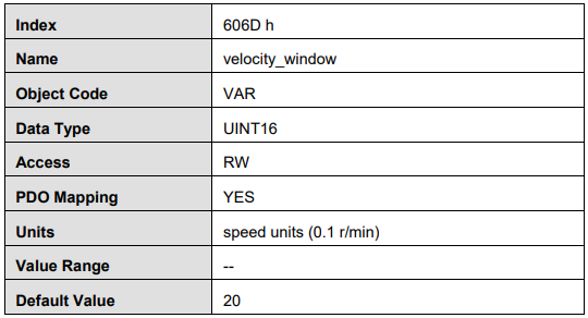
velocity_window
The difference between velocity_actual_value (606C h) and target_velocity (60FF h) is defined as actual velocity error window. If the actual velocity error window is always smaller than velocity_window(606D h) within the time set by velocity_window_time(606E h ), then bit 10 of status word (target_reached) will be set as 1 to indicate that the set velocity has been reached.
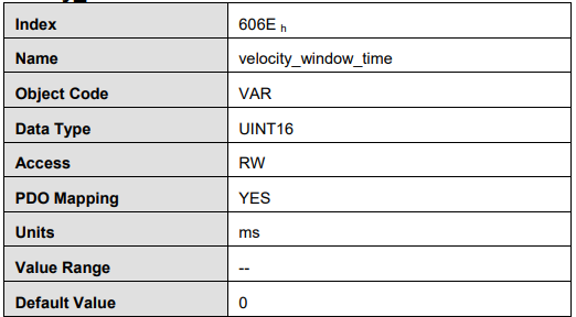
velocity_window_time
Velocity window comparator is composed of velocity_window_time and velocity_window.
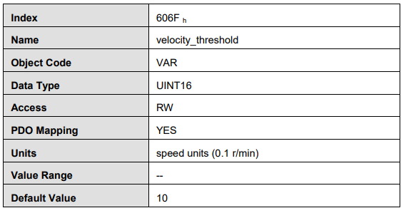
velocity_threshold
Velocity_threshold indicates a range close to zero speed in order to define if the servo motor has already stopped.
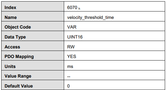
velocity_threshold_time
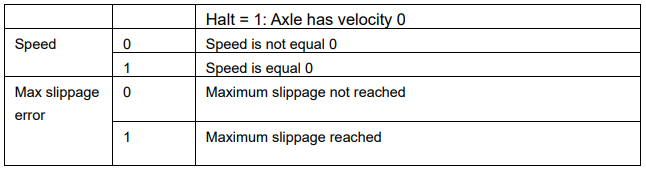
Velocity_threshold_time is used to set the shortest time when servo motor’s speed is under velocity threshold. The unit is: ms. When the time that servo motor’s speed is lower than the threshold is more than velocity_threshold_time, status word bit 12(speed is zero) will be set as 1.
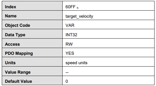
target_velocity
Target_velocity is reference speed.
5.7 Profile position mode
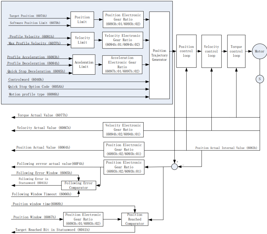
In the profile position mode, the motor position is controlled in accordance with the target position, target velocity , acceleration and deceleration, until it reaches the target position.
The following figure shows the block diagram of the profile position mode.
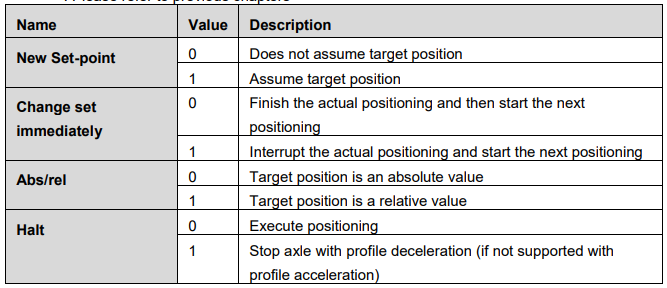
5.7.1 Control word

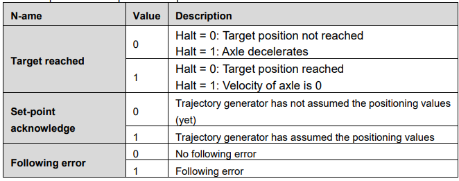
5.7.2 State word

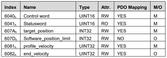
5.7.3 Parameters related to position control
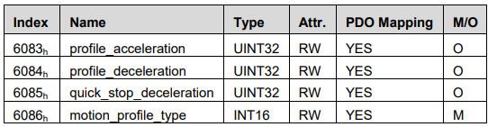
target_position
Target_position is reference position and this position could be an incremental value or an absolute value. It is up to bit6 of control word.
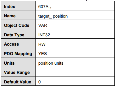
profile_velocity
Profile_velocity is the speed that the servo motor could finally reach after acceleration.
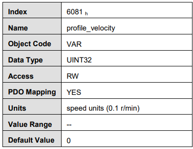
end_velocity
End_velocity is the speed when servo motor reaches the target_position. Normally we set this value as 0 in order to stop the servo motor when the servo motor reaches the requested position. But in continuous multiple position, this value could be set as a non-zero value.
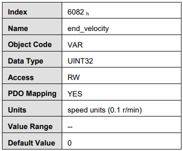
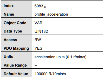
profile_acceleration
Profile_acceleration is the acceleration speed before reaching the target position.
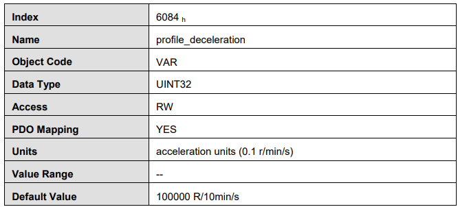
profile_deceleration
Profile_deceleration is the deceleration speed before reaching the target position.
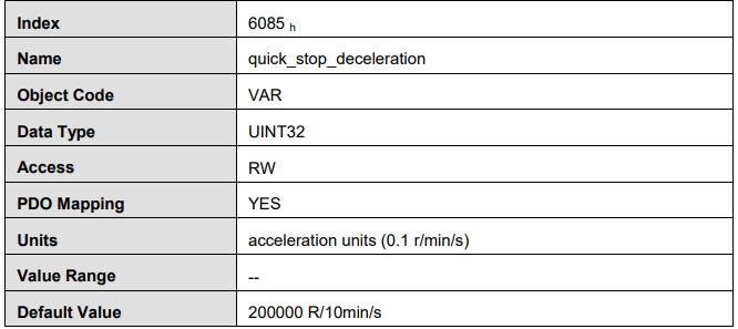
quick_stop_deceleration
Quick_stop_deceleration is the deceleration speed in Quick Stop
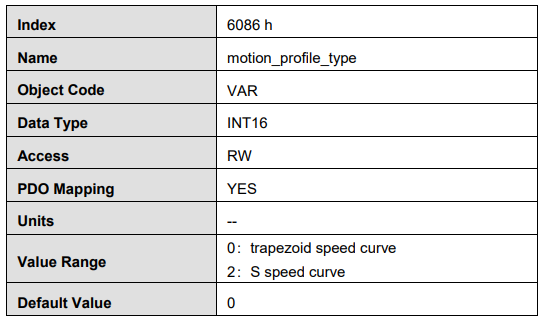
motion_profile_type
Motion_profile_type is used to select the motion curve. Now we only support trapezoid speed curve and S speed curve.
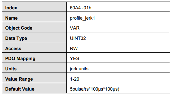
profile_jerk1
Profile_jerk1 is used to set the jerk of speed profile. The value is more smaller,the speed changing is more smooth.
5.7.4 Function description
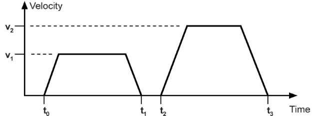
There are two methods to allocate a reference position.
Single step setting:
After reaching the target position, servo drive will inform the master that Reach the target position. And the servo drive will start new motion after getting new target position. Before getting the new reference position, the velocity of the servo motor is zero.
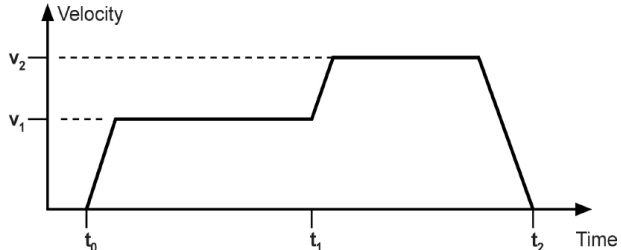
Continuous setting:
After reaching the target position, the servo motor will keep moving toward next target position which is set in advance. In this way, the servo motor could move continuously without pause. Between two reference positions, the servo motor doesn’t need to decelerate to zero.
Above two methods could be switched to each other by using control word bit 4, bit 5 and statues word bit 12 (set_point_acknowledge) in real time. Through handshaking mechanism, we could pause the position control in the process and use these bits above to reset the target position and then re-active and operate.
Single step setting procedure:
At first, set the NMT status into Operational and set the control mode parameter (6060 h) as 1.
According to the actual demand, we could set the target position (target_positon: 607A h) and so on.
We need set bit4 (new_set_point) of the control word as 1, bit 5 (change_set_immediately) as 0, bit 6 (absolute/comparative) should be determined by whether the reference target position is an absolute value or a comparative value.
We use bit12 (set_point_acknowledge) of the status word to configure the servo drive acknowledge mechanism. And then we start to operate position control.
After reaching the target position, servo drive will need to respond through bit 10 (target_reached) of the status word. And then servo drive will follow the program to keep moving or accept new target position.
Continuous step setting procedure:
1 At first, we need to set NMT status into operational and set control mode (6060 h) as 1. According to actual demand, we need to set the first target position (target_position: 607A h), target speed, acceleration/deceleration and other relevant parameters.
Set bit 4 (new_set_point) of control word as 1. Set bit 5 (change_set_immediately) as 0. Set bit6 (absolute/comparative) according to the type of object position.
Set bit 12 (set_point_acknowledge) of the status word and then start to operate position control.
Set the second target position (target_position: 607A h), target speed, acceleration/deceleration speed.
Set bit4 (new_set_point) as 1, bit 5 (change_set_immediately) as 0. Set Bit6 (absolute/comparative) according to the target position type.
After reaching the first target position, the servo drive will not stop and keep moving toward the second target position. After reaching the second target position, the servo drive will respond through status word bit 10 (target_reached). And then the servo motor will follow the program to keep moving or accept new target position.
5.8 Interpolation position mode
5.8.1 Control word

*: please refer to previous chapters
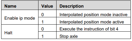
5.8.2 State word

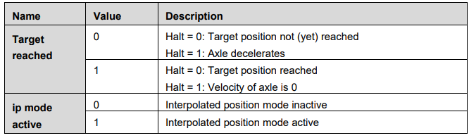
5.8.3 Parameters related to interpolation position control

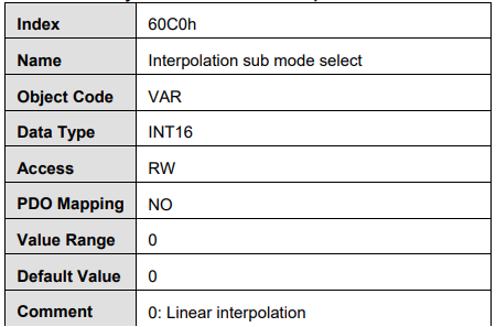
Interpolation sub mode select
Interpolation sub mode select is used to select the method of interpolation under IP control. ProNet servo drive only offers linear interpolation.
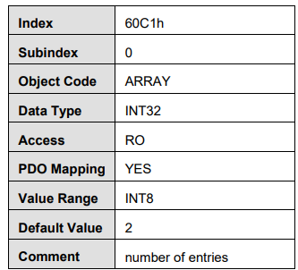
Interpolation data record
Interpolation data record is used to reserve interpolation potion data. Our servo drive’s interpolation command only uses the first data whose subindex is 1.
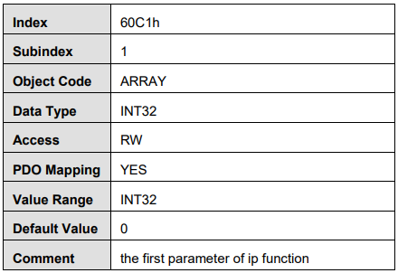
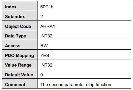
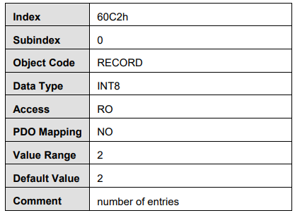
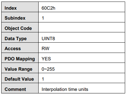
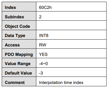
Interpolation time period
Interpolation time period is used to reserve the time data of interpolation position.
5.9 Profile torque mode
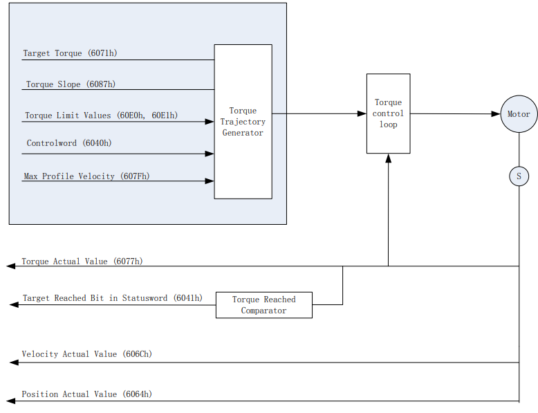
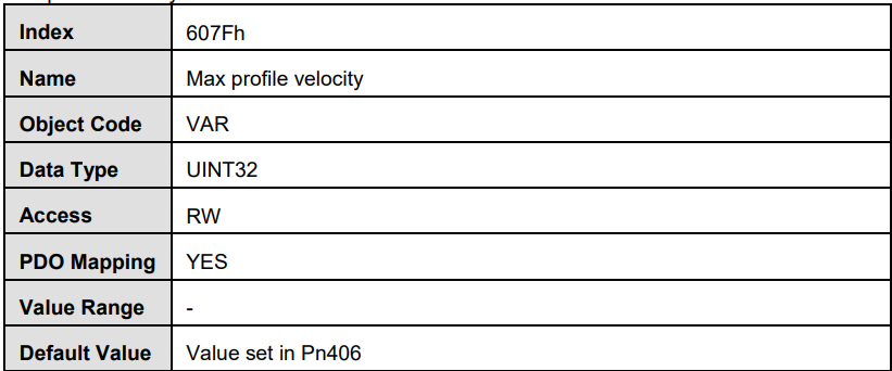
Profile torque mode operates the controller outputs a target torque. Servo drive outputs signal to control the motor according to the target torque and acceleration. Speed limit is 607Fh.
The following figure shows the block diagram of the profile torque mode.
5.9.1 Control word of profile torque mode

*: refer to previous chapters

5.9.2 Status word of profile torque mode

*: refer to previous chapters
5.9.3 Relevant parameters of profile torque mode
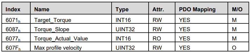
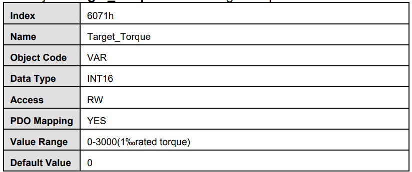
Target_Torque
The object Target_Torque is store target torque set value.
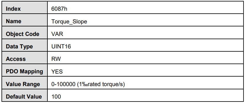
Torque_Slope
The object Torque_Slope determines the destination torque acceleration to store.
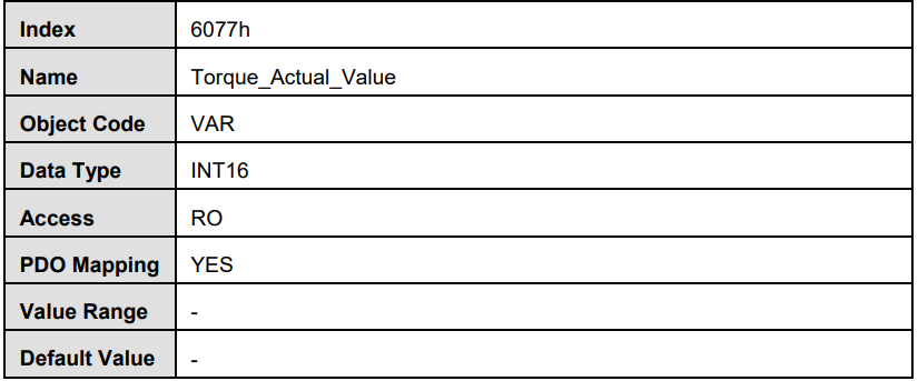
Torque_Actual_Value
Max profile velocity
5.10 Cyclic synchronous position mode
Cyclic synchronous position mode is similar to position interpolation mode. In this control mode, the master could offer extra speed and torque to achieve speed and torque feed forward control. The interpolation cycle time defines the time for target position updating. In this case, interpolation cycle time is the same as sync time.
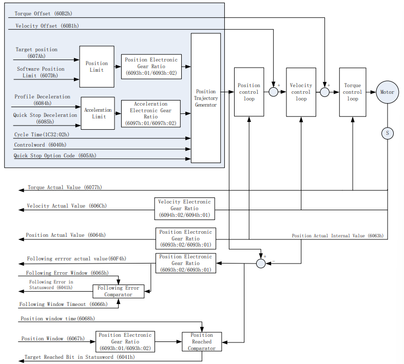
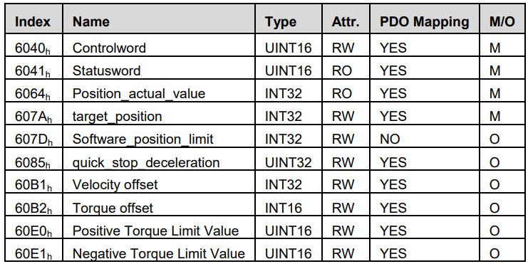
Refer to the objects are as follows:
5.11 Cyclic synchronous velocity mode (ProNet-□□□EG-EC only)
In cyclic synchronous velocity mode,the host controller give a target speed value to the servo drive periodically. And the servo drive control the motor according to the target velocity value. The following figure shows the control mode:
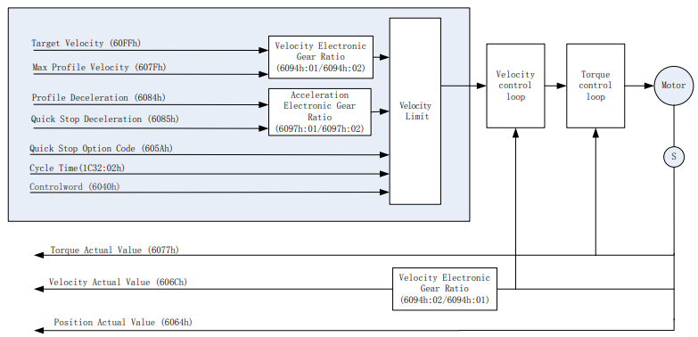
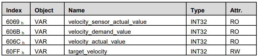
Refer to the objects are as follows:
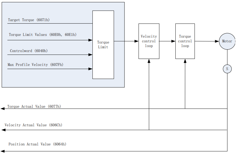
5.12 Cyclic synchronous torque mode
In cyclic synchronous torque mode,the host controller give a target torque value to the servo drive periodically. And the servo drive control the motor according to the target torque value. The following figure shows the control mode:
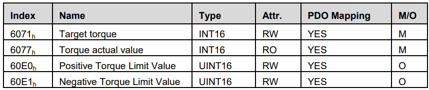
Refer to the objects as follows:
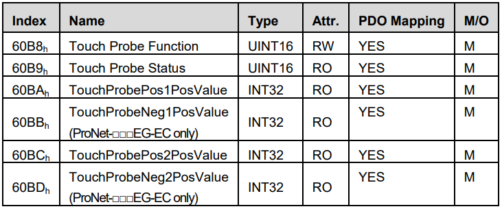
5.13 Touch Probe function
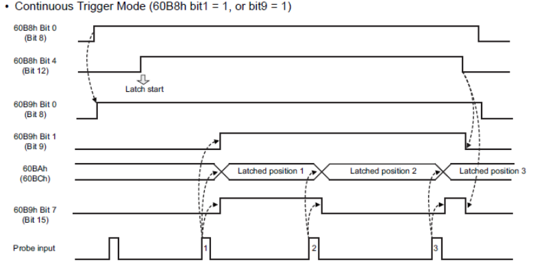
Touch probe function can store the location of the motor when the trigger condition occurs. So controller can use the location to calculate. Refer to the objects as follows:
The application principle are as follows:
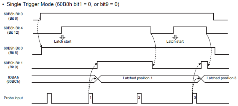
Touch Probe Function(0x60B8)
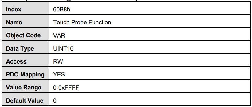
The object is configured to the touch probe function.
Touch Probe Function(60B8h)
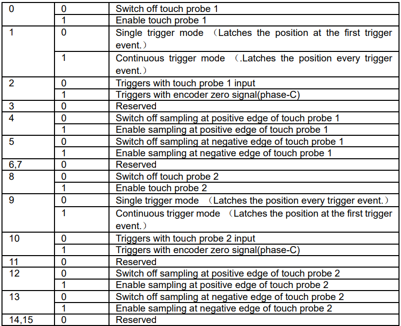
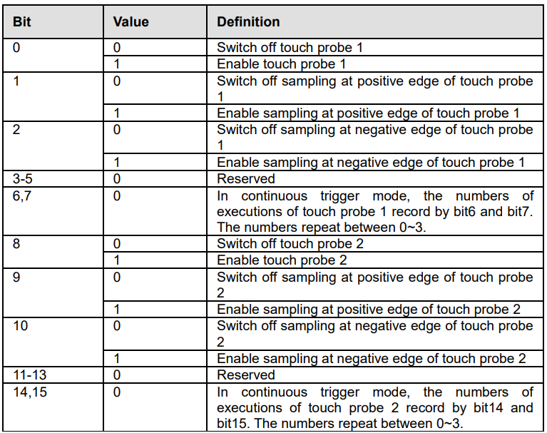
The definition of each bit is as follows:

The terminals of probe1 input and probe2 input are allocated to CN1* by Pn509 and Pn510. Specific content refers to appendix B.
* The terminals of probe1 input and probe2 input are allocated to CN1_3 and CN1_4 by Pn209.(ProNet-□□□EG-EC only)
Touch Probe Status(60B9h)
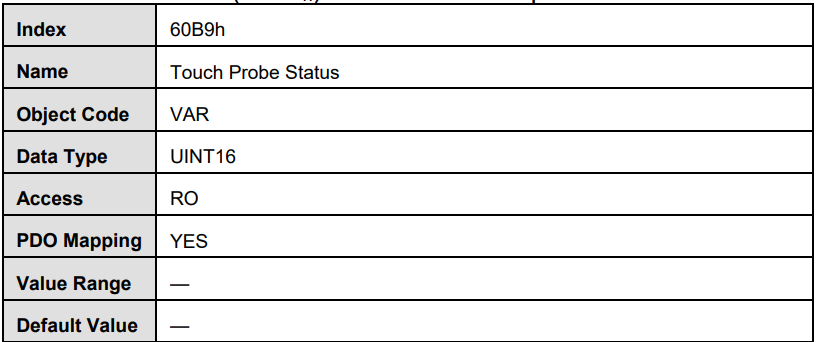
Touch Probe Status(60B9h) shows the touch probe status.
Touch Probe Status(60B9h)
The definition of each bit is as follows:
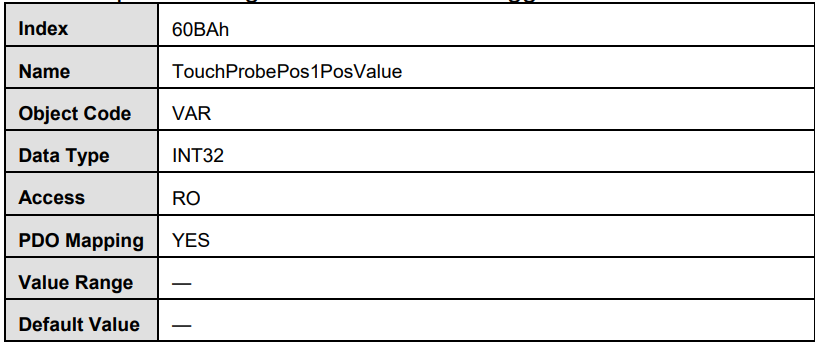
TouchProbePos1PosValue(60BAh)
TouchProbePos1PosValue(60BAh)shows the location of the motor when the positive edge of Touch Probe1 trigger condition occurs.
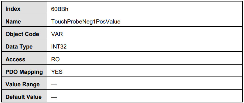
TouchProbeNeg1PosValue(60BBh)(ProNet-□□□EG-EC only)
TouchProbeNeg1PosValue(60BBh)shows the location of the motor when the negative edge of Touch Probe1 trigger condition occurs.
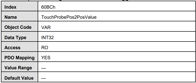
TouchProbePos2PosValue(60BCh)
TouchProbePos2PosValue(60BCh)shows the location of the motor when the positive edge of Touch Probe2 trigger condition occurs.
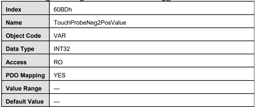
TouchProbeNeg2PosValue(60BDh)(ProNet-□□□EG-EC only)
TouchProbeNeg2PosValue(60BDh)shows the location of the motor when the negative edge of Touch Probe2 trigger condition occurs.
Pn209、Pn210 (ProNet-□□□EG-EC only)
Pn209 is Touch Probe input channel signal selection.
Pn210 is Touch Probe input signal filtering time.
5.14 Torque limit Function
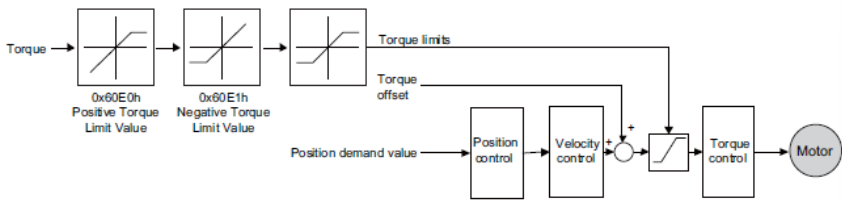
The torque is limited by 0x60E0,0x60E1. The following figure shows the block diagram of the torque limit function.
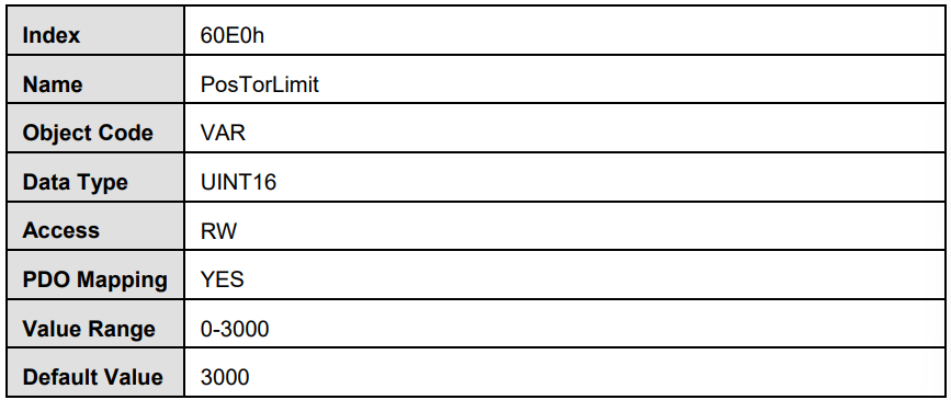
PosTorLimit(0x60E0)
PosTorLimitL:positive torque limit,unit:0.1% rated torque
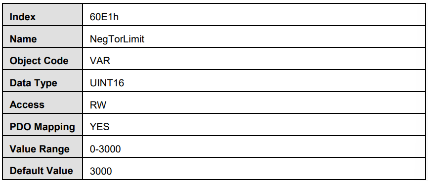
NegTorLimit(0x60E1)
NegTorLimit: negative torque limit,unit: 0.1% rated torque
5.15 Digital Input /Output
In some situations, some switches (such as the origin signal and limit signal) are not sent to the servo drive directly, but sent by the host. You need to use the object 60FE-01h (Physical outputs) to transfer the relevant signals.

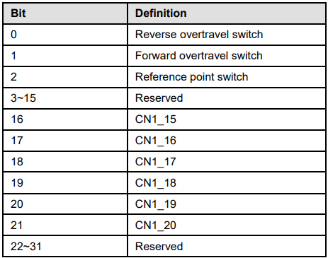
Bit16-bit19 correspond to CN1 interfaces. And only the bit of bitmask(60FE:02h) is set to 1, the corresponding bit is effective. For the bus transfer need, also need to enable bus transmission by Pn512/Pn513.
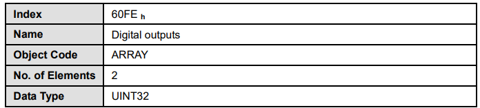
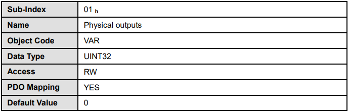
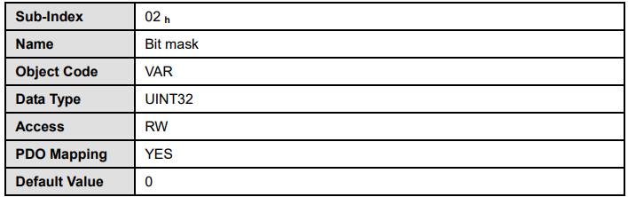
If the host needs to monitor switch input signals of the servo drive, the host can read the object 60FDh (Inputs Digital) to obtain. The definition is as follows:
5.16 Absolute Encoder Setup(Fn010、Fn011)
Setting up the absolute encoder in the following cases.
·When starting the machine for the first time,set Pn002.2 to 0.
·When an encoder error alarm (A.45~A.48, A.51) is generated.
Please use the panel operator or bus in the servo drive for setup. Use
SDO to reset absolute encoder multiturn data and alarm as follows:
1. Writing 1 into 321B by SDO can enabled Fn010.
2. Writing 1 into 321C by SDO can enabled Fn011.
Note:
1. Encoder setup operation is only possible when the servo is OFF.
2. If the absolute encoder alarms(A.45~A.48,A.51 ) are displayed, cancel the alarm by using the same method as the setup. They cannot be cancelled with the servo drive alarm reset input signal(/ALM-RST).
3. Any other alarms that monitor the inside of the encoder should be cancelled by turning OFF the power.
5.17 Conversion factors (factor group)
Servo controllers will be used in a huge number of applications: As direct drive, with gear or for linear drives. To allow an easy parameterization for all kinds of applications, the servo controller can be parameterized in such a way that all values like the demand velocity refer to the driven side of the plant. The necessary calculation is done by the servo controller.
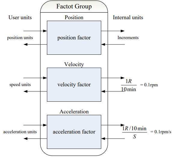
The default setting of the Factor Group is as follows:
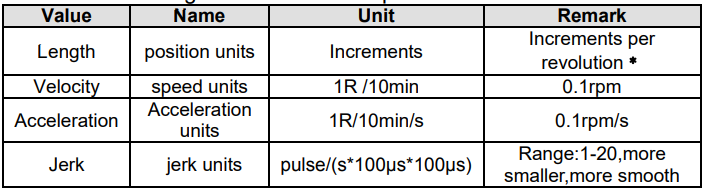
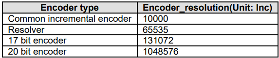
﹡: Common incremental encoder: 10000P/R
Resolver: 65536P/R
17bit incremental encoder: 131072P/R
17bit absolute encoder: 131072P/R
20bit absolute encoder: 1048576P/R

5.17.2 Position factor
The object position factor converts all values of length of the application from Position units into the internal unit increments (encoder resolution equals 1 Revolution). It consists of numerator and divisor:

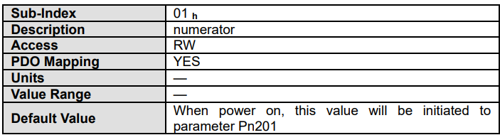
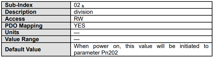
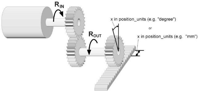
To calculate the position factor the following values are necessary: gear_ratio Ratio between revolutions on the driving side (RIN) and revolutions on the driven side (ROUT). feed_constant Ratio between revolutions on the driven side (ROUT) and equivalent motion in position_units (e.g. 1 rev = 360°)
The calculation of the position_factor is done with the following equation:

Note:
5.17.3 Velocity factor
The object velocity factor converts all speed values of the application from speed_units into the internal unit revolutions 0.1rpm. It consists of numerator and divisor

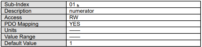
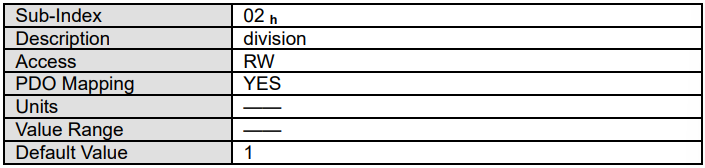
In principle the calculation of the velocity factor is composed of two parts: A conversion factor from internal units of length into position_units and a conversion factor from internal time units into user defined time units (e.g. from seconds to minutes). The first part equals the calculation of the position_factor. For the second part another factor is necessary for the calculation:
time_factor_v
Ratio between internal and user defined time units (z.B. 1 min = 1/10 10 min)
gear_ratio
Ratio between revolutions on the driving side (RIN) and revolutions on the driven side (ROUT).
feed_constant
Ratio between revolutions on the driven side (ROUT) and equivalent motion in position_units (e.g. 1 R = 360°
The calculation of the velocity factor is done with the following equation:

5.17.4 Acceleration factor
The object acceleration_factor converts all acceleration values of the application from acceleration_units into the internal unit (0.1rpm)。It consists of numerator and divisor:

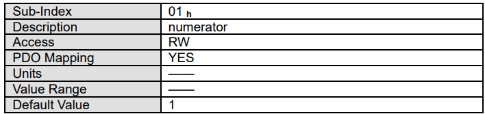
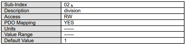
The calculation of the acceleration_factor is also composed of two parts: A conversion factor from internal units of length into position_units and a conversion factor from internal time units squared into user defined time units squared (e.g. from seconds2 to minutes2). The first part equals the calculation of the position_factor.
For the second part another factor is necessary for the calculation
time_factor_a
Ratio between internal time units squared and user defined time units squared (z.B.:1min2 = 1min*min = 60s*1min =60/10 10min/s)
gear_ratio
Ratio between revolutions on the driving side (RIN) and revolutions on the driven side (ROUT).
feed_constant
Ratio between revolutions on the driven side (ROUT) and equivalent motion in position_units (e.g. 1 R = 360°
The calculation of the acceleration_factor is done with the following equation:
