
4. Operation
4.1 Trial Operation
Make sure that all wiring has been completed prior to trial operation.
Perform the following three types of trial operation in order. Instructions are given for speed control mode (standard setting) and position control mode. Unless otherwise specified, the standard parameters for speed control mode (factory settings) are used.
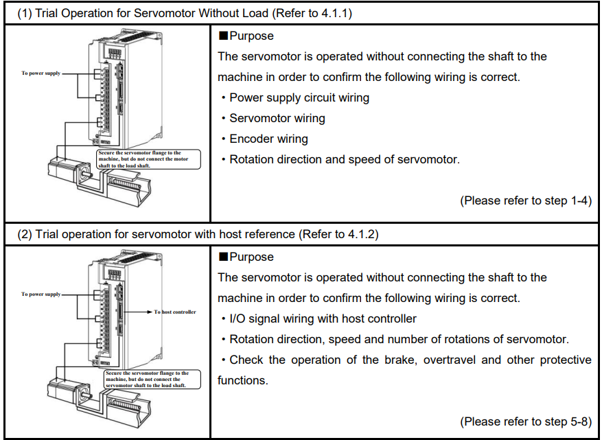
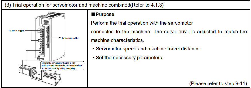
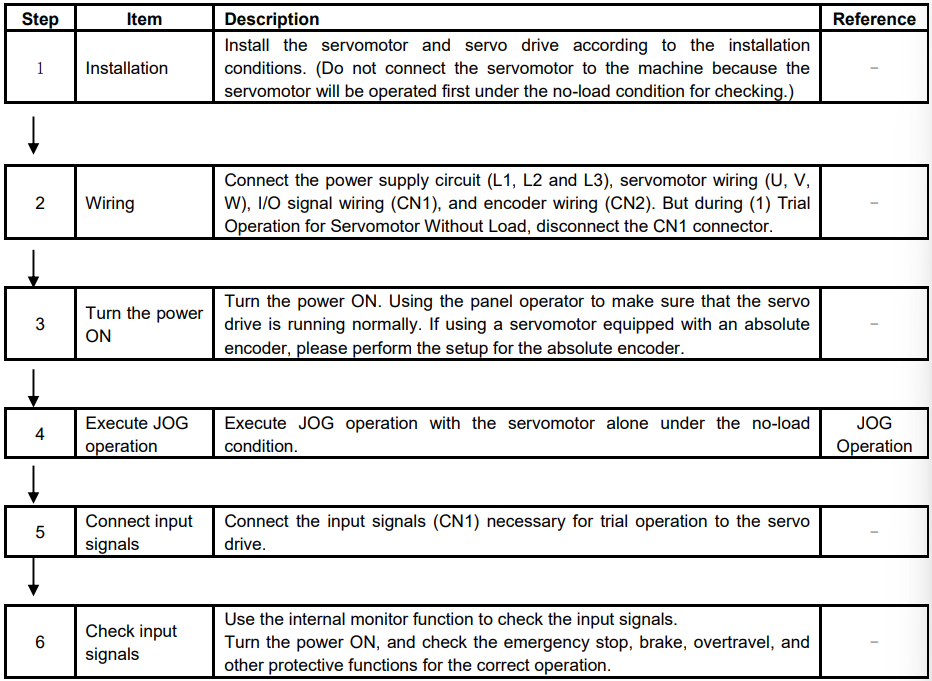
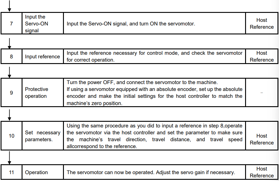
4.1.1 Trial Operation for Servomotor Without Load

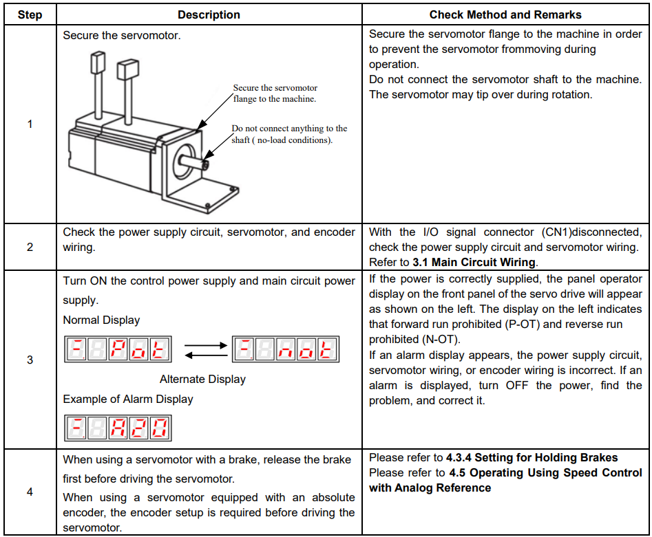
In this section, confirm the cable connections of the main circuit power supply, servomotor and encoder. Incorrect wiring is generally the reason why servomotors fail to operate properly during the trial operation.
Confirm the wiring, and then conduct the trial operation for servomotor without load according to the following steps.
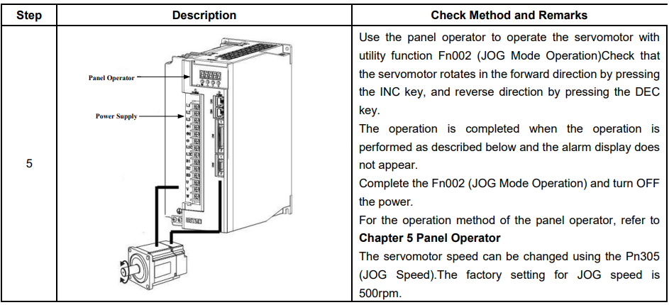
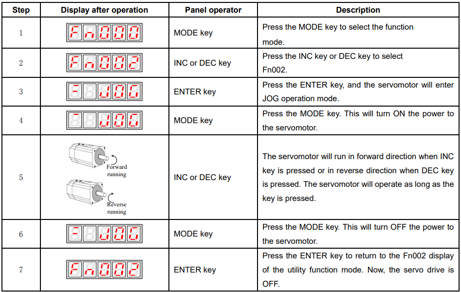
JOG Mode Operation (Fn002)
Note:
The servomotor’s rotation direction depends on the setting of parameter Pn001.0(Direction Selection).
The example above describes operation with Pn001.0 in the factory setting.

The servomotor can be operated using only the panel operator without reference from the host controller.
Please note that the Forward Run Prohibited (P-OT) and Reverse Run Prohibited (N-OT) signals are invalid during JOG mode operation.
4.1.2 Trial Operation for Servomotor without Load from Host Reference
NOTE: this function is available for ProNet-□□□MG servo drives only.
Check that the servomotor move reference or I/O signals are correctly set from the host controller to the servo drive.
Also check the wiring and polarity between the host controller and servo drive, and the servo drive operation settings are correct. This is the final check before connecting the servomotor to the machine.
(1)Servo ON Command from the Host
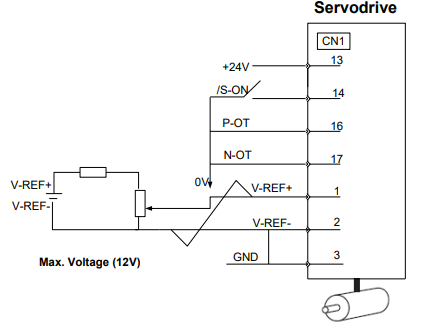
The following circuits are required: External input signal circuit or equivalent.
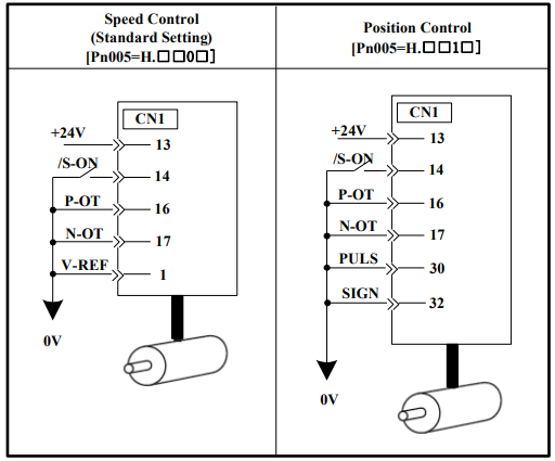
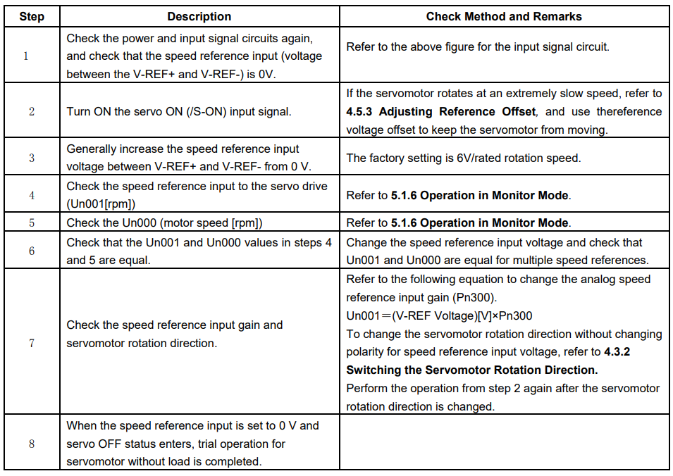
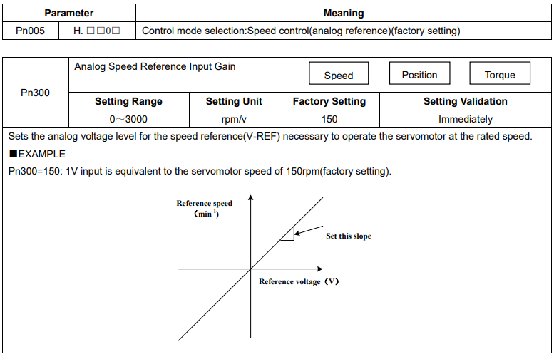
(2)Operating Procedure in Speed Control Mode (Pn005=H.□□0□)
The following circuit is required: External input signal circuit or equivalent.
■When Position Control is configured at the Host
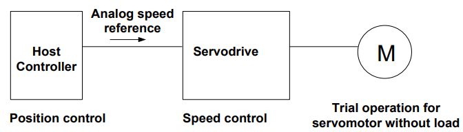
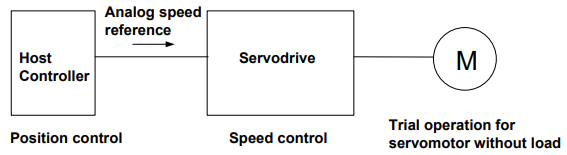
When the servo drive conducts speed control and position control is conducted at the host controller, perform the operation below,following the operation in Operation Procedure in Speed Control Mode (Pn005=H.□□0□).
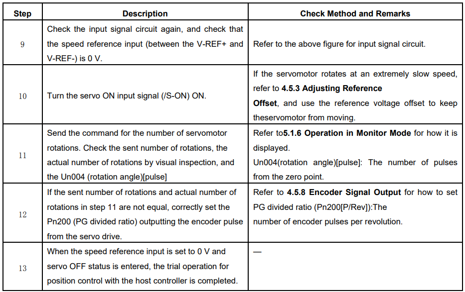
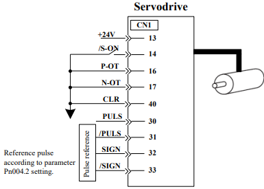
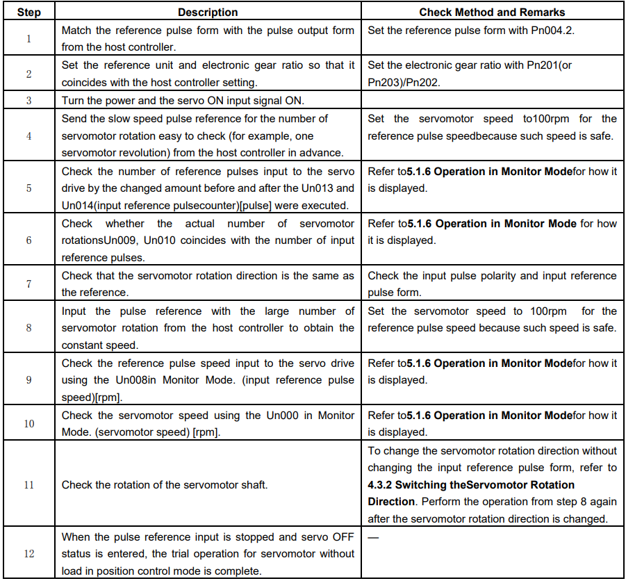
(3)Operating Procedure in Position Control Mode (Pn005=H.□□1□)
The following circuit is required: External input signal circuit or equivalent.
4.1.3 Trial Operation with the Servomotor Connected to the Machine

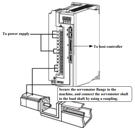
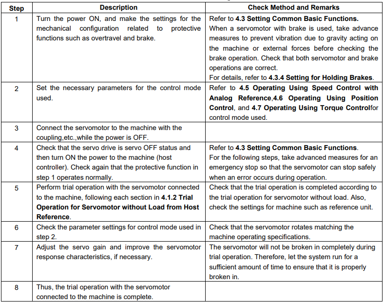
Follow the procedure below to perform the trial operation.
4.1.4 Trial Operation for Servomotor with Brakes
Holding brake operation of the servomotor can be controlled with the brake interlock output (/BK) signal of the servo drive.
When checking the brake operation,take advance measures to prevent vibration due to gravity acting on the machine or external forces. Check the servomotor operation and holding brake operation with the servomotor separated from the machine.If both operations are correct, connect the servomotor to the machine and perform trial operation.
Refer to 4.3.4 Setting for Holding Brakes for wiring on a servomotor with brakes and parameter settings.
4.1.5 Position Control by Host Controller
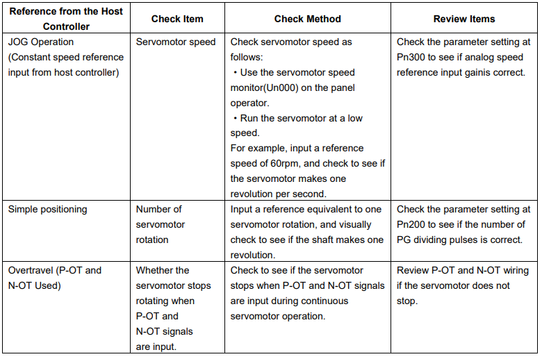
As described above, be sure to separate the servomotor and machine before performing trial operation of the servomotor without a load. Refer to the following table, and check the servomotor operation and specifications in advance.
4.2 Control Mode Selection
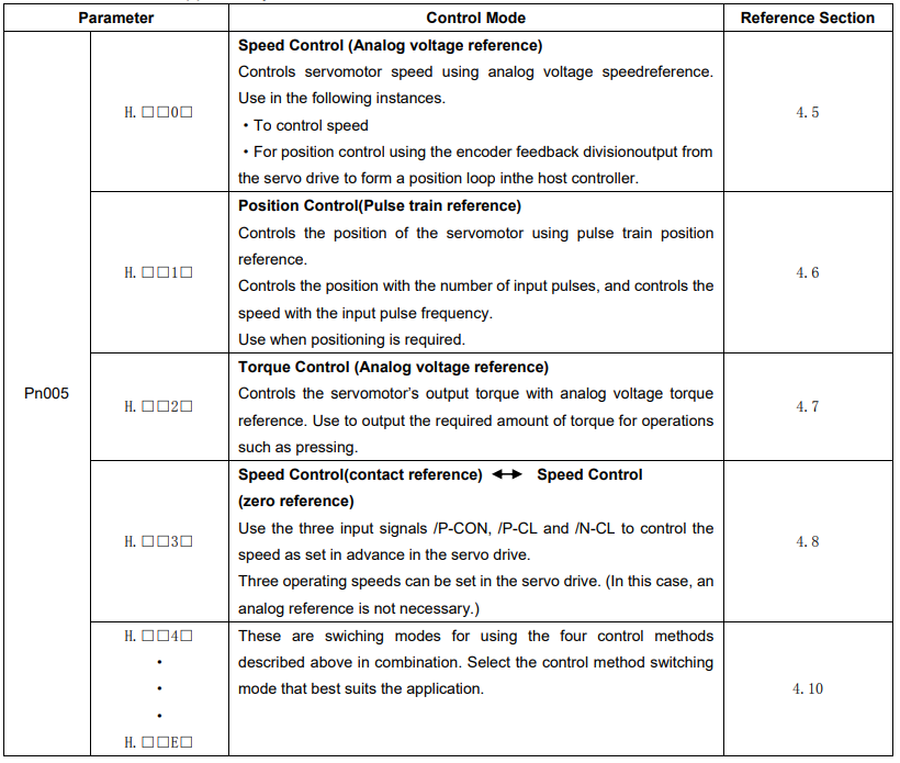
The control modes supported by the ProNet series servo drives are described below.
4.3 Setting Common Basic Functions
4.3.1 Setting the Servo ON Signal
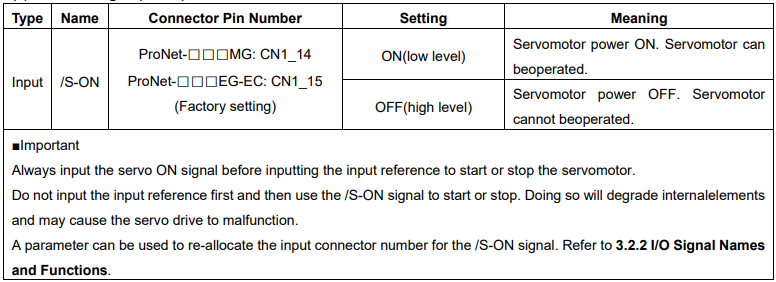
This sets the servo ON signal (/S-ON) that determines whether the servomotor power is ON or OFF.
(1)Servo ON signal(/S-ON)
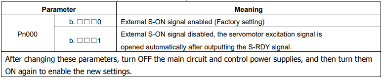
(2) Enabling/Disabling the Servo ON Signal
A parameter can be always used to set the servo ON condition. This eliminates the need to wire /S-ON, but care must be taken because the servo drive can operate as soon as the power is turned ON.
4.3.2 Switching the Servomotor Rotation Direction
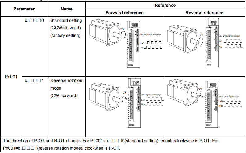
The rotation direction of the servomotor can be switched without changing the reference pulse to the servo drive or the reference voltage polarity.
This causes the rotation the servo motor shaft is rotating to change. The output signal polarity, such as the encoder pulse output and the analog monitor signal from the servo drive do not change.
The standard setting for “forward rotation” is counterclockwise as viewed from the servomotor load end.
4.3.3 Setting the Overtravel Limit Function
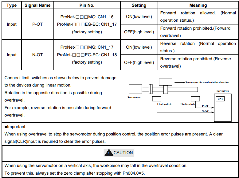
The overtravel limit function forces movable machine parts to stop if they exceed the allowable range of motion and turn ON a limit switch.
(1)Connecting the overtravel signal
To use the overtravel function, connect the following overtravel limit switch to the corresponding pin number of servo drive CN1 connector correctly.
(2)Enabling/Disabling the Overtravel Signal
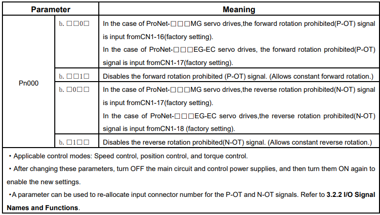
A parameter can be set to disable the overtravel signal. If the parameter is set, there is no need to wire the overtravel input signal.
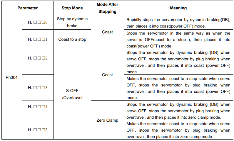
(3) Selecting the Servomotor Stop Method
This is used to set the stop method when an overtravel(P-OT,N-OT)signal is input while theservomotor is operating
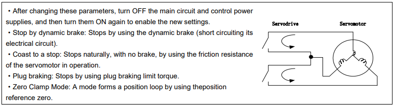
·Dynamic brake is an emergency stop function, and one of the general methods to cause a servomotor sudden stop.
·Dynamic brake suddenly stops a servomotor by shorting its electrical circuit.
·If the servomotor is frequently started and stopped by turning the power ON/OFF or using the servo ON signal(/S-ON), the DB circuit will also be repeatedly operated, degrading the servo drive’s internal elements.
·Use the speed input reference and position reference to control the starting and the stopping of the servomotor.
(4)Setting the Stop Torque for Overtravel

4.3.4 Setting for Holding Brakes
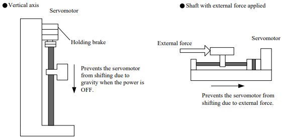
The holding brake is used when the servo drive controls a vertical axis.
A servomotor with the brake option helps prevent movable parts from shifting due to gravity when power is removed from the servo drive.
(Refer to 4.1.4 Trial Operation for Servomotor with Brakes.)
1. The servomotor with the built in brake, is a de-energization brake. It is used to hold the servomotor and cannot be used as a braking purposes. Use the holding brake only to hold a stopped servomotor.
2. When operating using only a speed loop, turn OFF the servo and set the input reference to 0V when the brake is applied.
3. When forming a position loop, do not use a mechanical brake while the servomotor is stopped because the servomotor enters servolock status.
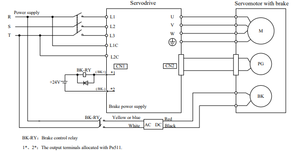
(1) Wiring Example
Use the servo drive sequence output signal /BK and the brake power supply to form a brake ON/OFF circuit.
The following diagram shows a standard wiring example
(2) Brake interlock output

(3) Allocating Brake Interlock Output (/BK)
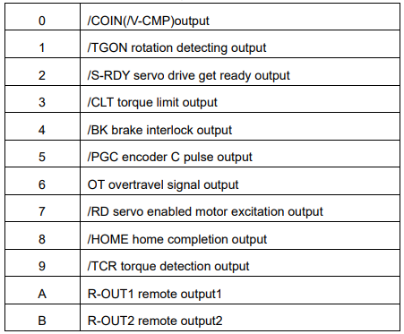
Brake interlock output (/BK) is not used with the factory setting.The output signal must be allocated.
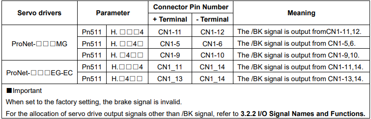
Parameter Pn511 description as following:
(4) Setting the Brake ON/OFF Timing after the Servomotor Stops
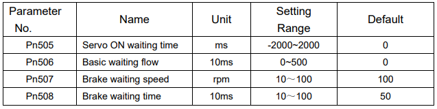
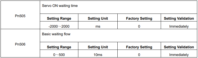
With the factory setting, the /BK signal is output at the same time as the servo is turned OFF. The servo OFF timing can be changed with a parameter.
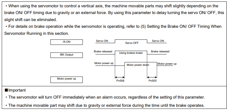
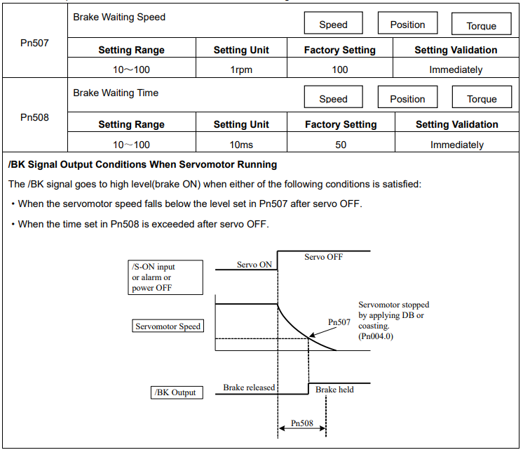
(5) Setting the Brake ON/OFF Timing When Servomotor Running
The following parameters can be used to change the /BK signal output conditions when a stop reference is output during servomotor operation due to the servo OFF or an alarm occuring.
4.3.5 Instantaneous Power Loss Settings
Determines whether to continue operation or turn the servo OFF when the power supply voltage to the servo drive main circuit is instantaneously interrupted.

4.4 Absolute Encoders
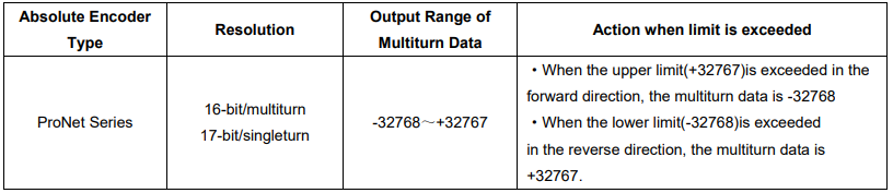
The absolute position can be read by the MODBUS protocol. In the actual control, the MODBUS protocol can read the initial position when the servomotor is stopped (S-OFF), then the real-time position during the servomotor is running can be found from the number of PG divided output pulses.
4.4.1 Selecting an Absolute Encoder
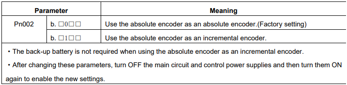
An absolute encoder can also be used as an incremental encoder
4.4.2 Handling Battery
In order for the absolute encoder to retain position data when the power is turned OFF, the data must be backedup by a battery.
Please purchase the special cable and battery case mabe by Estun if an absolute encoder is used.
Install the battary to the encoder cable:
A.Open the shell of the battery case.
B.Install the battery according to the following diagram.
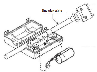
C.Cover the shell of the battery case
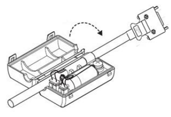
4.4.3 Replacing Battery
The servo drive will generate an absolute encoder battery alarm(A.48) when the battery voltage drops below about 3.1V.
Battery Replacement Procedure
1. Replace the battery with only the servo drive control power supply turned ON.
2. After replacing the battery, using the panel operator with utility function Fn011 to cancel the absolute encoder battery alarm(A.48).
3. Turn ON the servo drive power back again. If it operates without any problems, the batteryreplacement has been completed.
Note:
·The servo drive will generate an absolute encoder battery alarm(A.48) when the battery voltage drops below about 3.1V.
·If an absolute encoder battery alarm(A.47) occurred, it means the battery voltage drops below about 2.5V,and the multiturn data is lost.Please reset the absolute encoder after changing the battery.
4.4.4 Absolute Encoder Setup(Fn010, Fn011)
Setting up the absolute encoder in the following cases.
·When starting the machine for the first time,set Pn002.2 to 0.
·When an encoder error alarm (A.45~A.48, A.51) is generated.
Use the panel operator in the servo drive for setup.
Note:
1. Encoder setup operation is only possible when the servo is OFF.
2. If the absolute encoder alarms(A.45~A.48, A.51 ) are displayed, cancel the alarm by using the same method as the setup. They cannot be cancelled with the servo drive alarm reset input signal(/ALM-RST).
3. Any other alarms that monitor the inside of the encoder should be cancelled by turning OFF the power.
4.5 Operating Using Speed Control with Analog Reference
NOTE: this function is available for ProNet-□□□MG servo drives only.
4.5.1 Setting Parameters
4.5.2 Setting Input Signals
(1) Speed Reference Input
Input the speed reference to the servo drive using the analog voltage reference to control the servomotor speed in proportion to the input voltage.

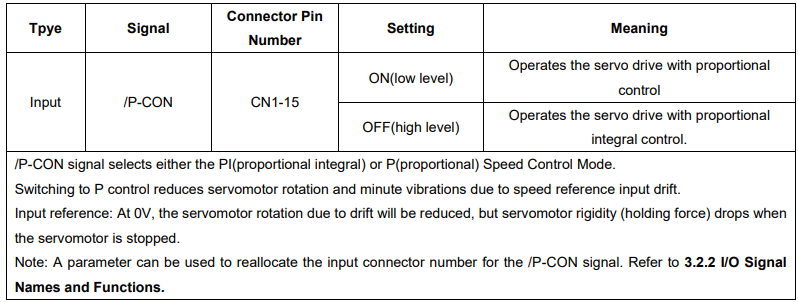
(2) Proportional Control Reference (/P-CON)
4.5.3 Adjusting Reference Offset
When using the speed control, the servomotor may rotate slowly even if 0V is specified as the analog voltage reference.
This happens if the host controller or external circuit has a slight offset (in the unit of mV) in the reference voltage.
Adjustments can be done manually or automatically by using the panel operator. Refer to 5.2 Operation in Utility Function Mode.
The servo drive automatically adjusts the offset when the host controller or external circuit has the offset in the reference voltage.
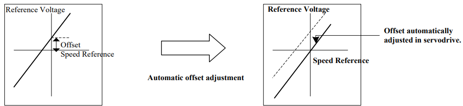
After completion of the automatic adjustment, the amount of offset is stored in the servo drive. The amount of offset can be checked in the speed reference offset manual adjustment mode (Fn004). Refer to 4.5.3 (2) Manual Adjustment of the Speed Reference Offset.
(1) Automatic Adjustment of the Speed Reference Offset
The automatic adjustment of reference offset (Fn003) cannot be used when a position loop has been formed with a host controller and the error pulse is changed to zero at the servomotor stop due to servolock. Use the speed reference offset manual adjustment (Fn004) described in the next section for a position loop.
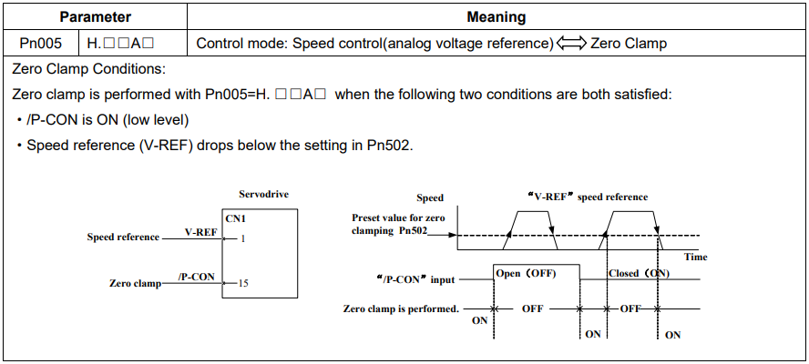
The zero-clamp speed control function can be used to force the servomotor to stop while the zero speed reference is given. Refer to4.5.7 Using the Zero Clamp Function.
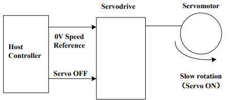
Note:The speed reference offset must be automatically adjusted with the servo OFF.
Adjust the speed reference offset automatically in the following procedure.
1.Turn OFF the servo drive and input the 0V reference voltage from the host controller or external circuit
2.Press the MODE key to select the utility function mode.
3.Press the INC or DEC key to select parameter Fn003.
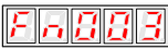
4.Press the ENTER key to enter into the speed reference offset automatic adjustment mode.

5.Press the MODE key for more than one second, the reference offset will be automatically adjusted.
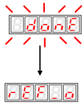
7.Press ENTER key to return to the Fn003 display of the utility function mode.
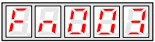
8.Thus, the speed reference offset automatic adjustment is completed.
(2) Manual Adjustment of the Speed Reference Offset
Use the speed reference offset manual adjustment (Fn004) in the following situations:
·If a loop is formed with the host controller and the postion error pulse is set to be zero when servolock is stopped.
·To deliberately set the offset to some value
·To check the offset data set in the speed reference offset automatic adjustment mode.
This function operates in the same way as the reference offset automatic adjustment mode (Fn003), except that the amount of offset is directly input during the adjustment.
The offset setting range and setting unit are as follows:
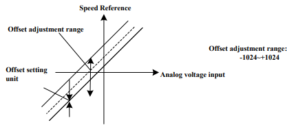
Adjust the speed reference offset manually in the following procedure.
1.Press the MODE key to select the utility function mode.
2. Press the INC or DEC key to select parameter Fn004.
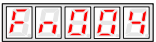
3. Press the ENTER key to enter into the speed reference offset manual adjustment mode.
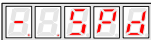
4. Turn ON the servo ON (/S-ON) signal. The display will be shown as below.

5. Press the ENTER key for one second to display the speed reference offset amount.
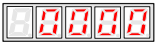
6. Press the INC or DEC key to adjust the amount of offset.
7. Press the ENTER key for one second to return to the display in step 4.
8. Press the ENTER key to return to the Fn004 display of the utility function mode.
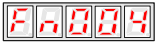
9. Thus, the speed reference offset manual adjustment is completed.
4.5.4 Soft Start
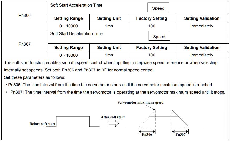
The soft start function converts the stepwise speed reference inside the servo drive to a consistent rate of acceleration and deceleration.
Pn310 can be used to select the soft start form:
0: Slope; 1: S curve; 2: 1 st -order filter; 3: 2nd -order filter
4.5.5 Speed Reference Filter Time Constant

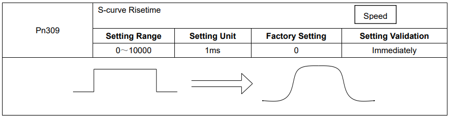
4.5.6 S-curve Risetime
4.5.7 Using the Zero Clamp Function
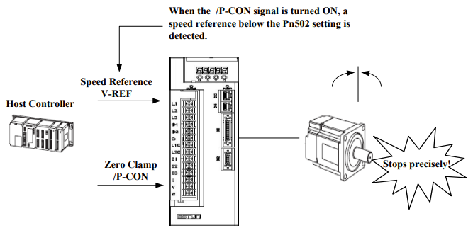
(1) Zero Clamp Function
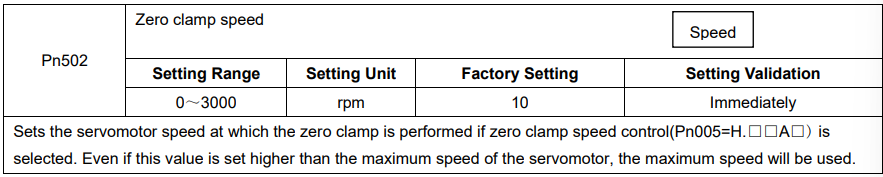
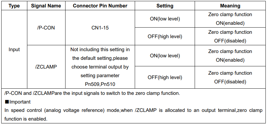
The zero clamp function is used for systems where the host controller does not form a position loop for the speed reference input. When the zero clamp signal (/P-CON) is ON, a position loop is formed inside the servo drive as soon as the input voltage of the speed reference (V-REF) drops below the servomotor zero clamp speed. The servomotor ignores the speed reference and quickly stops and locks the servomotor. The servomotor is clamped within ±1 pulse when the zero clamp function is turned ON, and will still return to the zero clamp position even if it is forcibly rotated by an external force.
(2) Parameter Setting
(3) Input Signal Setting
4.5.8 Encoder Signal Output
Encoder feedback pulses processed inside the servo drive can be output externally.
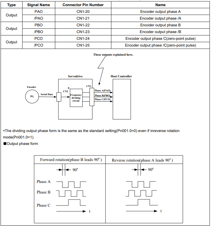
If the servomotor is not equipped with an absolute encoder, the servomotor needs two full rotations before using the servo drive's Phase-C pulse output as the zero point reference.
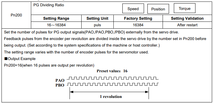
Dividing:Dividing means that the divider converts data into the pulse density(Pn200) based on the pulse data of the encoder installed on the servomotor, and outputs it. The setting unit isnumber of pulses/revolution.
Pulse Dividing Ratio Setting
4.5.9 Speed coincidence output
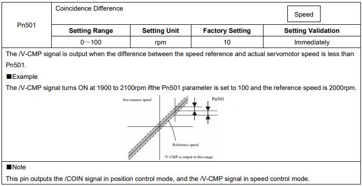
The speed coincidence (/V-CMP) output signal is output when the actual servomotor speed during speed control is the same as the speed reference input. The host controller uses the signal as an interlock.

4.6 Operating Using Position Control
NOTE: this function is available for ProNet-□□□MG servo drives only.
Set the following parameters for position control using pulse trains.