
5. Panel Operator
1 Basic Operation
5.1.1 Functions on Panel Operator
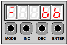
The panel operator is a built-in operator that consists of display section and keys located on the front panel of the servo
drive.
Parameter setting, status display ,and execution of utility function are enabled using the panel operator.
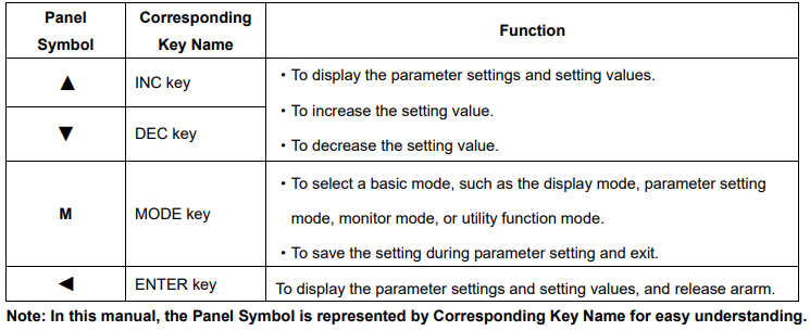
The names and functions of the keys on the panel operator are shown as follows:
5.1.2 Resetting Servo Alarms
Servo alarms can be reset by pressing the ENTER key when the panel operator in display mode. Servo alarms can also be reset using the CN1-39(/ALM-RST) input signal.
There is no need to clear the servo alarms if it turns the main circuit power supply OFF.
Note:After an alarm occurs, remove the cause of the alarm before resetting it.
5.1.3 Basic Mode Selection
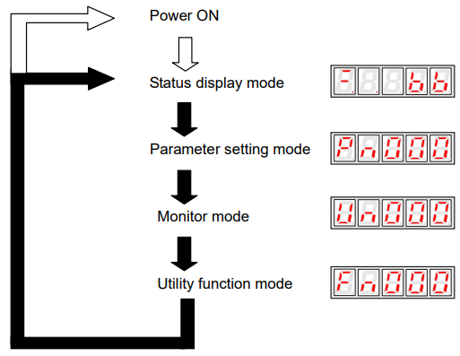
The basic modes include status display mode, parameter setting mode, monitor mode, and utility function mode. Each time the MODE key is pressed, the next mode in the sequence is selected.
Select a basic mode to display the operation status, set parameters and operation references.
The basic mode is selected in the following order.
5.1.4 Status Display Mode
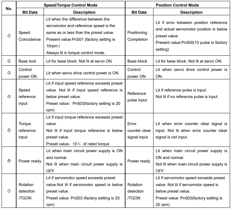
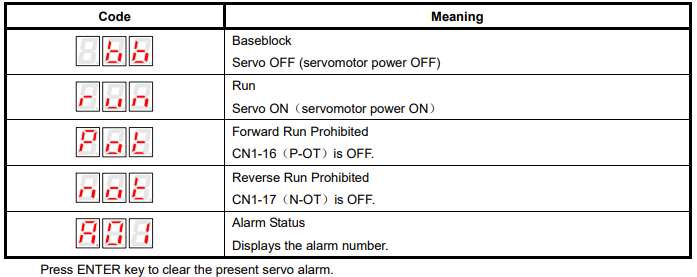
The status display mode displays the servo drive status as bit data and codes.
Selecting Status Display Mode
The status display mode is selected when the power supply is turned ON. If it is not displayed, select this mode by pressing MODE key.
Note that the display differs between the speed/torque control and position control types.
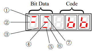
Bit Data Display
Codes Display
5.1.5 Operation in Parameter Setting Mode
The servo drive offers a large number of functions, which can be selected or adjusted by the parameter settings. Refer to A.1 Parameter List for details.
■Parameter Setting Procedures
The parameter settings can be used for changing parameter data. Before changing the data, check the permitted range of the parameter.
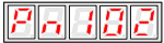
The example below shows how to change parameter Pn102 from “100” to “85”.
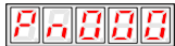
1. Press MODE key to select the parameter setting mode.
2. Press INC key or DEC key to select parameter number.
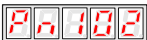
3. Press ENTER key to display the current data of Pn102.
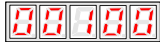
4. Press the INC or DEC key to change the data to the desired number 00085. Hold the key to accelerate the changing of value. When the maximum value or minimum value is reached, pressing INC or DEC key respectively, will have no effect.
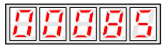
5. Press the ENTER or MODE key once to return to the display of Pn102.
5.1.6 Operation in Monitor Mode
The monitor mode allows the reference values input into the servo drive, I/O signal status, and servo drive internal status to be monitored.
■Using the Monitor Mode
The example below shows how to display the value (1500) stored in Un001.
1.Press MODE key to select the monitor mode.
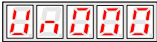
2.Press the INC or DEC key to select the monitor number to display.
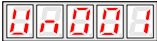
3.Press the ENTER key to display the data for the monitor number selected at step 2.
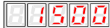
4.Press the ENTER key once more to return to the monitor number display
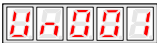
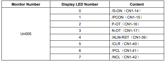
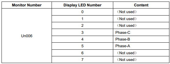
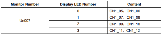
■List of Monitor Modes
Contents of Monitor Mode Display
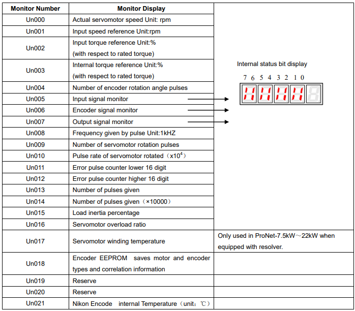
Contents of Bit Display:
5.2 Operation in Utility Function Mode
In utility function mode, the panel operator can be used to run and adjust the servo drive and servomotor.
The following table shows the parameters in the utility function mode.
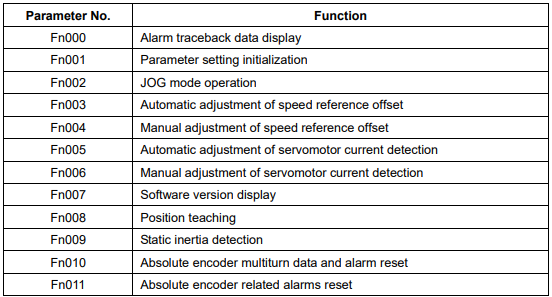
Note: Fn010、Fn011 only can be used when the servomotor mounted the absolute encoder.
5.2.1 Alarm Traceback Data Display
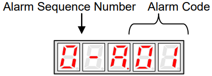
The alarm traceback display can display up to 10 previously occurred alarms.The alarm is displayed on Fn000, which is stored in the alarm traceback data.
Follow the procedures below to confirm alarms which have been generated.
1. Press the MODE key to select the utility function mode.
2. Press the INC or DEC key to select the function number of alarm trace back data display.
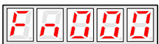
3. Press the ENTER key once, the latest alarm data is displayed.
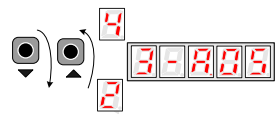
4. Press the INC or DEC key to display other recent alarms that have occurred.
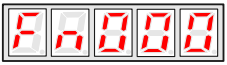
5. Press the ENTER key, the display will return to Fn000.
Note: Hold the ENTER key for one second with alarm code displaying, all the alarm traceback datas will be cleared.
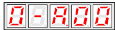
5.2.2 Parameter Settings Initialization
Follow the procedures below to execute the parameter settings initialization.
1. Press the MODE key to select the utility function mode.
2. Press the INC or DEC key to select the function number of parameter settings initialization.
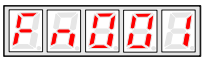
3. Press the ENTER key to enter into parameter settings mode.
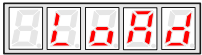
4. Hold the ENTER key for one second, the parameters will be initialized.
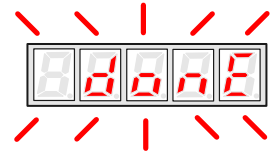
5. Release the ENTER key to ruturn to the utility function mode display Fn001
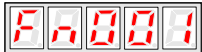
Note:
Press the ENTER key during servo ON does not initialize the parameter settings.
Initialize the parameter settings with the servo OFF.
5.2.3 Operation in JOG Mode
Follow the procedures below to operate the servomotor in JOG mode.
1. Press the MODE key to select the utility function mode.
2. Press the INC or DEC key to select the function number of JOG mode operation.
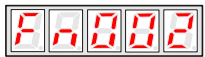
3. Press the ENTER key to enter into JOG operation mode.
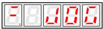
4. Press the MODE key to enter into servo ON (servomotor power ON) status.
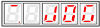
5. Press the MODE key to switch between the servo ON and servo OFF status.The servo drive must be in servo ON status when the servomotor is running.
6. Press the INC or DEC key to rotate the servomotor.

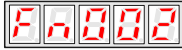
7. Press the ENTER key to return to utility function mode display Fn002. Now the servo is OFF(servomotor power OFF).
5.2.4 Automatic Adjustment of the Speed Reference Offset
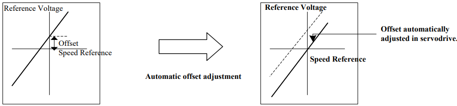
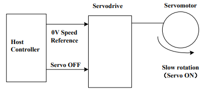
When using the speed/torque (analog reference) control, the servomotor may rotate slowly even if 0V is specified as the analog voltage reference.
This happens if the host controller or external circuit has a slight offset (in the unit of mV) in the reference voltage.
The reference offset automatic adjustment mode automatically measures the offset and adjusts the reference voltage. It can adjust both speed and torque reference offset.
The servo drive automatically adjusts the offset when the host controller or external circuit has the offset in the reference voltage
After completion of the automatic adjustment, the amount of offset is stored in the servo drive. The amount of offset can be checked in the speed reference offset manual adjustment mode (Fn004). Refer to 4.5.3 (2) Manual Adjustment of the
Speed Reference Offset.
The automatic adjustment of reference offset (Fn003) cannot be used when a position loop has been formed with a host controller and the error pulse is changed to zero at the servomotor stop due to servolock. Use the speed reference offset manual adjustment for a position loop.
The zero-clamp speed control function can be used to force the servomotor to stop while the zero speed reference is given.
Note: The speed reference offset must be automatically adjusted with the servo OFF.
Adjust the speed reference offset automatically in the following procedure.
1. Turn OFF the servo drive, and input the 0V reference voltage from the host controller or external circuit.
2. Press the MODE key to select the utility function mode.
3. Press the INC or DEC key to select the utility function number Fn003.
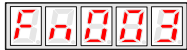
4. Press the ENTER key to enter into the speed reference offset automatic adjustment mode.

5. Press the MODE key for more than one second, the reference offset will be automatically adjusted
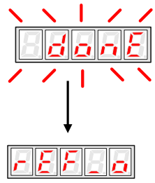
6. Press the ENTER key to return to the utility function mode display Fn003.
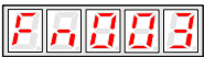
7. Thus, the speed reference offset automatic adjustment is complete.
5.2.5 Manual Adjustment of the Speed Reference Offset
Manual adjustment of the speed/torque reference offset is used in the following cases:
If a position loop is formed with the host controller and the error is zeroed when servolock is stopped.
To deliberately set the offset to some value.
Use this mode to check the offset data that was set in the automatic adjustment mode of the speed/torque reference offset.
This mode operates in the same way as the automatic adjustment mode, except that the amount of offset is directly input during the adjustment.
The offset adjustment range and setting unit are as follows.
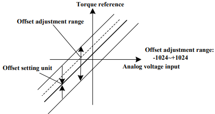
Note:
When the offset using in automatic adjustment exceeds the manual adjustment range (-1024~+1024), manual adjustment will be invalid.
Adjust the analog reference offset manually in the following procedure:
1. Press the MODE key to select the utility function mode.
2. Press the INC or DEC key to select the utility function number Fn004.
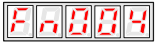
3. Press the ENTER key to enter into the speed reference offset manual adjustment mode.

4. Turn ON the servo-ON signal, the display is shown as follows:

5. Hold the ENTER key, the speed reference offset will be displayed.
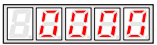
6. Press the INC or DEC key to change the offset.
7. Hold the ENTER key to return to the display in step 4.
8. Press ENTER key to return to the utility function mode display Fn004..
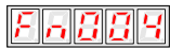
Thus, the speed reference offset manual adjustment is complete.
5.2.6 Offset-adjustment of Servomotor Current Detection Signal
Automatic servomotor current detection offset adjustment is performed at ESTUN before shipping. Basically, the user does not need to perform this adjustment.
Perform this adjustment only if highly accurate adjustment is required for reducing torque ripple caused by current offset.
This section describes the automatic and manual servomotor current detection offset adjustment.
Note:
·Offset-adjustment of the servomotor current detection signal is possible only while power is supplied to the main circuit power supply and with the servo is the OFF state.
·Execute the automatic offset adjustment if the torque ripple is too big when compared with that of other servo drives.
·If this function, particularly manual adjustment, is executed carelessly, it may worsen the characteristics.
■Automatic Offset-adjustment of Servomotor Current Detection Signal
Adjust the servomotor current detection signal automatically in the following procedure:
1. Press the MODE key to select the utility function mode.
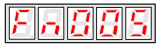
2. Press the INC or DEC key to select the utility function number Fn005.
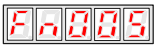
3. Press the ENTER key to enter into the automatic adjustment of the servomotor current detection signal mode.
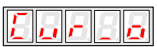
4. Press the MODE key,the display will blinks for one second. The offset will be automatically adjusted.
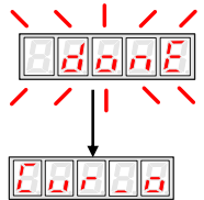
5. Press the ENTER key to return to the utility function mode display Fn005.
Thus, the automatic offset-adjustment of the servomotor current detection signal is complete
■Manual Offset-adjustment of Servomotor Current Detection Signal
Adjust the servomotor current detection signal manually in the following procedure.
1. Press the MODE key to select the utility function mode.
2. Press the INC or DEC key to select the utility function number Fn006.
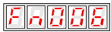
3. Press the ENTER key to enter into the manual adjustment of the servomotor current detection signal.
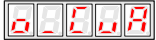
4. Press the MODE key to switch between the phase U(o _ CuA) and phase V(1_ Cub) servomotor current detection offset adjustment.

5. Hold the ENTER key for one second to display the phase V offset amount.

6. Press the INC or DEC key to adjust the offset.

7. Press the ENTER key for one second to return to the display in step 3 or 4.
8. Press the ENTER key to return to the utility function mode display Fn006.
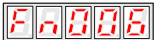
Thus, the manual offset-adjustment of the servomotor current detection signal is completed.
Note:
The adjusting range of the servomotor current detection offset is -1024 to +1024.
5.2.7 Software Version Display
Select Fn007 in utility function mode to check the current software version of the drive.
1. Press the MODE key to select the utility function mode.
2. Press the INC or DEC key to select the utility function number Fn007.
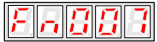
3. Press the ENTER key to display the DSP software version (the highest bit displays d or E or F or 0).
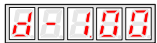
4. Press the MODE key to display the FGPA/CPLD software version (the highest bit displays P).
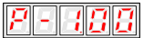
5. Press the MODE key to return to DSP software version display.
6. Press the ENTER key to return to the utility function mode display Fn007.
5.2.8 Position Teaching Function
Perform the position teaching function in the following procedure.
1. Press the MODE key to select the utility function mode.
2. Press the INC or DEC key to select the utility function number Fn008.
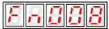
3. Press the ENTER key, the display will be shown as below.
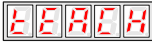
4. Press the ENTER key, the display will be shown as below.
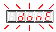
5. Release the ENTER key to complete position teaching function.
5.2.9 Static Inertia Detection
1. Press the MODE key to select the utility function mode.
2. Press the INC or DEC key to select the utility function number Fn009.
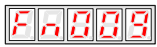
3. Press the ENTER key, the display will be shown as below.

4. Press the MODE key to rotate the servomotor, and the servomotor dynamic speed will be displayed.
5. The unit of the servomotor and load total inertia displayed when servomotor stops is kg.cm² Thus, the static inertia detection is complete.
Note:Make sure that the servomotor completes at least 6 full revolutions in the CCW direction before detection
5.2.10 Absolute Encoder Multiturn Data and Alarm Reset
1. Press the MODE key to select the utility function mode.
2. Press the INC or DEC key to select the utility function number Fn010.
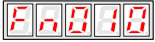
3. Press the ENTER key, the display will be shown as below.
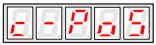
4. Press the MODE key to reset the absolute encoder multiturn data and alarm.
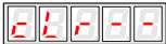
5. Thus the absolute encoder multiturn data and alarm reset is complete.
Important:
This function will clear the absolute position of the encoder; the mechanical safety must be noted. When the multiturn data is cleared, other encoder alarms will be reset at the same time.
5.2.11 Absolute Encoder Related Alarms Reset
1. Press the MODE key to select the utility function mode.
2. Press the INC or DEC key to select the utility function number Fn011.
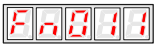
3. Press the ENTER key, the display will be shown as below.
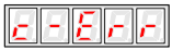
4. Press the MODE key to clear the alarms.
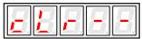
5. Thus the absolute encoder related alarms reset is complete