
6. MODBUS Communication
6.1 RS-485 Communication Wiring
ProNet series servo drives provide the MODBUS communication function with RS-485 interface,which can be used to easily set parameters or to perform monitoring operations and so on.
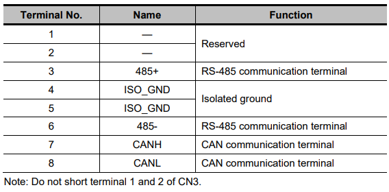
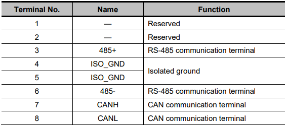
The definitions of the servo drive communication connector terminals are as follows.
CN3:
CN4:
Note:
1. The length of the cable should be less than 100 meters and in a environment with minimal electrical disturbance/interference. However, if the transmission speed is above 9600bps, please use the communication cable within 15 meters to ensure transmission accuracy..
2. A maximum of 31 servo drives can be connected when RS485 is used. Terminating resistances are used at both ends of the 485 network. If more devices are wanted to connect, use the repeaters to expand.
3. CN3 of servo drive is always used as communication cable input terminal,and CN4 is always used as communication cable output terminal(If still need to connect slave stations,the communication cable is connected from CN4 terminal to the next slave station; if need not, add balance resistor in CN4 terminal.).It is prohibited to connect CN3 of any two servo drives directly when multiple ProNet series servo drives are connected.
Example:
When a RS-485 network is composed of a PLC and three servo drives (A, B, and C), the cable wiring is shown as follows:
PLC→CN3 of A, CN4 of A→CN3 of B, CN4 of B→CN3 of C, CN4 of C→120Ω terminating resistance.
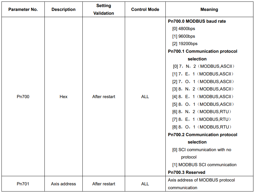
6.2 MODBUS Communication Related Parameters
6.3 MODBUS Communication Protocol
MODBUS communication protocol is only used when Pn700.2 is set to 1. There are two modes for MODBUS communication: ASCII (American Standard Code for information interchange) mode and RTU (Remote Terminal Unit) mode.
The next section describes the two communication modes.
6.3.1 Code Meaning
ASCII Mode:
Every 8-bit data is consisted by two ASCII characters. For example: One 1-byte data 64(Hexadecimal expression)is expressed as ASCII code ‘64’, which contains ‘6’ as ASCII code 36H and ‘4’ as ASCII code 34H.
ASCII code for number 0 to 9、character A to F are as follows:

RTU Mode:
Every 8-bit data is consisted by two 4-bit hexadecimal data, that is to say, a normal hexadecimal data. For example: decimal data 100 can be expressed as 64H by 1-byte RTU data.
Data Structure:
10-bit character form(7-bit data)
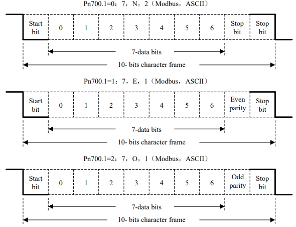
11-bit character form(8-bit data)
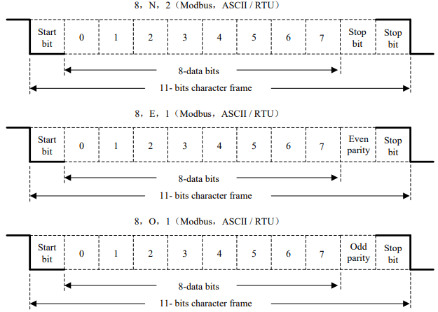
Communication protocol structure:
Data format of communication protocol:
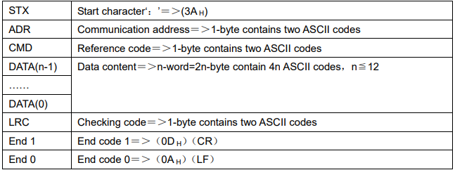
ASCII Mode:
RTU Mode:
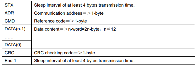
Communication protocol data format instructions are as follows:
STX(communication start)
ASCII mode:‘: ’character
RTU mode: Sleep interval of at least 4 bytes transmission time (automatically changed according to different communication speed).
ADR(communication address)
Valid communication address:1 to 254
For example: communicate with the servo drive which address is 32(20 in hex):
ASCII mode:ADR=‘2’,‘0’=>‘2’=32H,‘0’=30H
RTU mode:ADR=20H
CMD(command reference)and DATA(data)
Data structure is determined by command code. Regular command code is shown as follows:
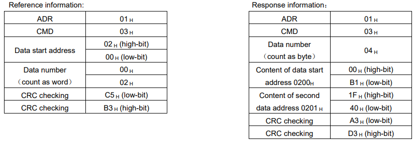
Command code: 03H,read N words(word),N ≦ 20.
For example: read 2 words starting from 0200 H from the servo drive which address is 01 H.
ASCII mode:
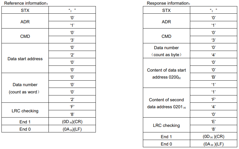
RTU mode:
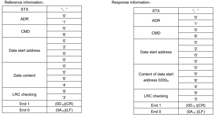
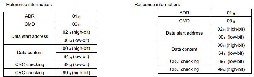
Reference code: 06H,write in one word
For example: write 100(0064 H)into 01H servo address 0200 H .
ASCII mode:
RTU mode:
LRC(ASCII mode)and CRC(RTU mode)error detection value calculation:
LRC calculation in ASCII mode:
ASCII mode uses LRC (Longitudinal Redundancy Check) error detection value. The exceeded parts (e.g. the total value is 128H of hex, then take 28H only) is taken off by the unit of 256 in the total value from ADR to the last information, then calculate and compensate, the final result is LRC error detection value.
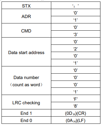
For example: read 1 word from 01H servo address 0201H
Add from ADR data to the last data.
01 H +03 H +02 H +01 H +00 H +01 H =08 H
The compensate value is F8H when 2 is used to compensate 08H, so LRC is “F”,”8”.
CRC calculation of RTU mode:
RTU mode uses CRC (Cyclical Redundancy Check) error detection value.
The process of CRC error detection value calculation is shown as follows:
Step 1: Load in a 16-bit register of FFFFH, named “CRC” register.
Step 2: Run XOR calculation between the first bit (bit 0) of instruction information and 16-bit CRC register’s low bit (LSB), and the result is saved to CRC register.
Step 3: Check the lowest bit (LSB) of CRC register, if it is 0, CRC register moves one bit to right; if it is 1, CRC register moves one bit to right, then run XOR calculation with A001H;
Step 4: Go to step 5 till the third step has been executed for 8 times, otherwise return to step 3.
Step 5: Repeat the steps from 2 to 4 for the next bit of instruction information, the comment of CRC register is the CRC error detection value while all the bits have been executed by the same way.
Note: After calculating out the CRC error detection value, the CRC low bit should be filled first in instruction information, and then fill the high bit of CRC.
Please refer to the following example:
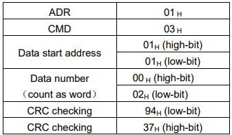
Read 2 words from the 0101H address of 01H servo. The final CRC register content calculated from ADR to the last bit of data is 3794H, and then the instruction information is shown as follows,
Please be sure that 94H is transmitted before 37H.
End1、End0(Communication is complete.)
ASCII mode:
Communication is ended with (0DH) - [carriage return] and (0AH) - [new line].
RTU mode:
When the time exceeds the sleep interval by at least 4 bytes transmission time while in the current communication speed, it means the communication is finished.
Example:
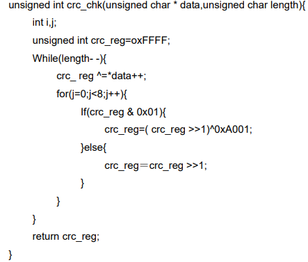
The following example uses C language to generate CRC value. The function needs two parameters.
unsigned char * data;
unsigned char length;
The function will return unsigned integer type CRC value.
6.3.2 Communication Error Disposal
Problems that occur during communication are a result of the following:
Data address is incorrect while reading/writing parameters.
The data is not within the parameter setting range while writing.
Data transmission fault or checking code fault when communication is disturbed.
When the first and second communication faults occur, the servo drive is running normally, and will feed back an error frame.
When the third communication fault occurs, transmission data will be recognized as invalid to give up, and no error frame is returned.
The format of error frame:
Host controller data frame:

Servo drive feeds back error frame:

Error frame responses code=command+80H
Error code=00H:Normal communication
=01H:Servo drive cannot identify the required functions
=02H: The required data address does not exist in the servo drive
=03H:The required data in servo drive is not allowed. (Beyond the maximum or minimum value of the parameter)
=04H:Servo drive starts to perform the requirement, but cannot achieve it.
For example: Servo drive axis number is 03H,write data 06H into parameter Pn100 is not allowed , because the range of parameter Pn100 is 0~0x0036. The servo drive will feedback an error frame, the error code is 03H (Beyond the parameter’s maximum value or minimum value).
Host controller data frame:

Servo drive feedback error frame:

Besides, if the data frame sent from host controller slave station address is 00H, it determines the data to be broadcast data. The servo drives will not feedback any frames.
6.3.3 Data Communication Address of Servo State
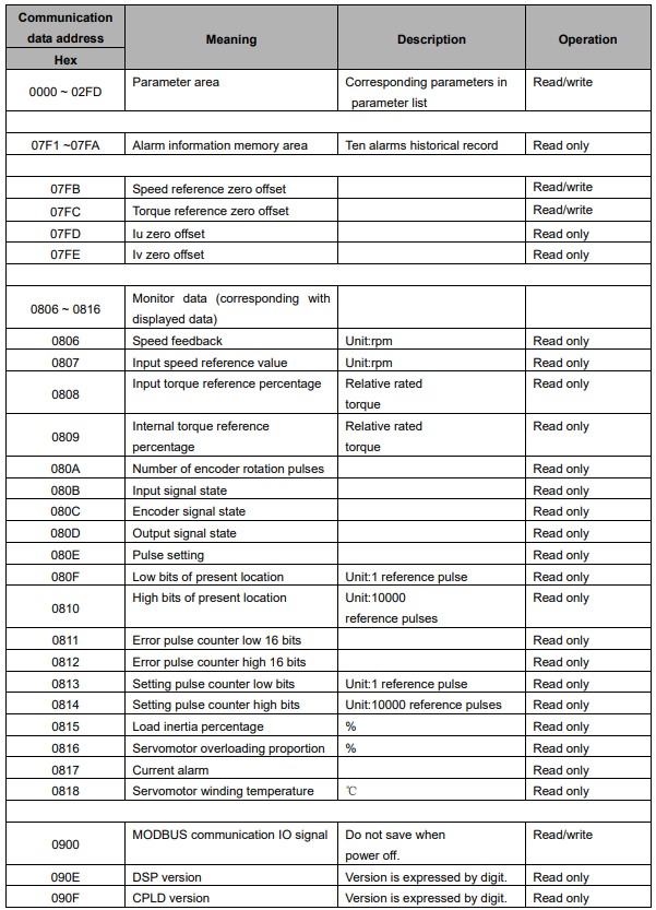
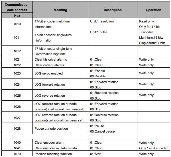
The communication parameter addresses are shown in the following table:
Note:
1. Parameter area(communication address 0000~00DEH)
Parameter address is relevant to the parameters in the parameter list.
For example, parameter Pn000 is relevant to communication address 0000H; parameter Pn101 is relevant to communication address 0065H. Read/write operation to address 0000H is the read/write operation to Pn000. If the communication input data is not within the parameter range, the data will be aborted, and servo drive will return an operation unsuccessful signal.
2. Alarm information storage area(07F1~07FAH)

3. Monitor data area(0806~0816H)
The monitor data is corresponding to servo drive panel displays Un000~Un016.
For example: the corresponding data of communication address 0807H (speed setting) is FB16H.
Therefore, the speed setting is -1258r/m.
4. MODBUS communication IO signal
Use communication to control digital IO signal. This data will not be saved after power off.
It is operated with Pn512 and Pn513 as the communication input IO signal. That is to say, when the parameters setting in Pn512 and Pn513 enable the IO bit, the IO can be controlled by communication.
5. Software version(090FH)
Use digit to represent servo drive software version. For example, if the read out data is D201H,it means the software version is D-2.01.