6. Device control
The following chapter describes how to control the servo controller using CANopen, i.e. how to switch on the power stage or to reset an error
6.1 State diagram (State machine)
Using CANopen the complete control of the servo is done by two objects. Via the controlword the host is able to control the servo, as the status of the servo can be read out of the statusword. The following items will be used in this chapter:
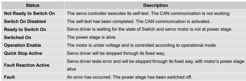
State: The servo controller is in different states dependent on for instance if the power stage is alive or if an error has occurred. States defined under CANopen will be explained in this chapter.
Example: SWITCH_ON_DISABLED
State Transition: Just as the states it is defined as well how to move from one state to another (e.g. to reset an error). These state transitions will be either executed by the host by setting bits in the controlword or by the servo controller itself, if an error occurs for instance.
Command: To initiate a state transition defined bit combinations have to be set in the controlword. Such bit combination are called command. Example: Enable Operation
State diagram: All the states and all state transitions together form the so called state diagram: A survey of all states and the possible transitions between two states.
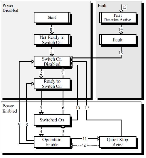
State diagram of the servo controller
The state diagram can be divided into three main parts: "Power Disabled" means the power stage is switched off and "Power Enabled" the power stage is active. The area "Fault" contains all states necessary to handle errors of the controller. The most important states have been highlighted in the Figure: After switching on the servo controller initializes itself and reaches the state SWITCH_ON_DISABLED after all. In this state CAN communication is possible and the servo controller can be parameterized (e.g. the mode of operation can be set to "velocity control"). The power stage remains switched off and the motor shaft is freely rotatable. Through the state transitions 2, 3 and 4 – principally like the controller enable under CANopen - the state OPERATION_ENABLE will be reached. In this state the power stage is live and the servo controller controls the motor according to the parameterized mode of operation. Therefore previously ensure that the servo controller has been parameterized correctly and the according demand value is zero. The state transition 9 complies with disabling the power stage, i.e. the motor is freely rotatable.
6.2 Relevant parameters of device control
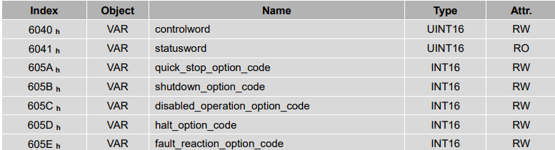
6.2.1 Controlword
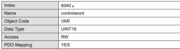

Controlword bit description is as below…

Bit0 ~ 3 and Bit7:
Transmit of status machine is triggered by 5 bits coordinated control code as below…
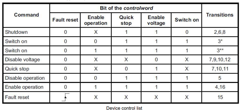
Note: X means this bit could be ignored.
Bit4、5、6、8:
The definition of this 4 bit is different in different control mode…
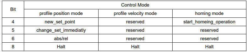
Other bits: all reserved
6.2.2 Statusword
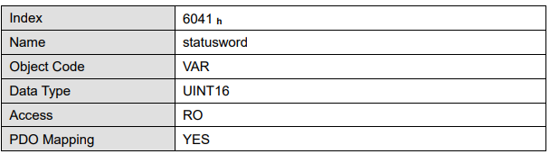

Explanation of statusword bit is as below:
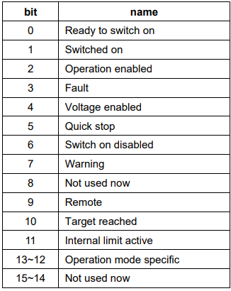
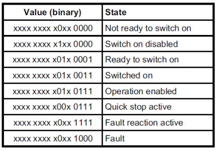
Bit0 ~ 3 , Bit5 and Bit6:
The combination of this bit indicates the status of drives.
Bit4: Voltage enabled
Main power is on when this bit is 1.
Bit5: Quick stop
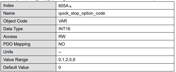
Driver will follow setting (605A h:quick_stop_option_code)to halt when this bit is 0.
Bit7: Warning
Driver detects alarm when this bit is 1.
Bit9: Warning
Servo can deal with Controlword when this bit is 1 and CANOPEN is enabled.
Bit10: Target reached
In different control modes the meaning of this bit is different. In profile position mode, when set position is reached, this bit is set. When Halt is booted, speed is reduced to 0 and this bit will be set. When new position is set, this bit will be cleared. In profile Velocity Mode, when the speed reaches the targeted speed, this bit will be set. When Halt is booted and speed is reduced to 0, this bit
is set.
Bit11: Internal limit active
When this bit is 1, it indicates that internal torque has surpassed the set value,or reached the max.forward/reverse run.It can be confirmed by reading object 60FDh(digital inputs).
Bit12, 13:
These 2 bits mean different in different control mode…

Other bits:
All reserved.
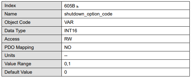
6.2.3 Shutdown_option_code
The object shutdown_option_code determines the behaviour if the state transition 8 (from OPERATION ENABLE to READY TO SWITCH ON) will be executed.

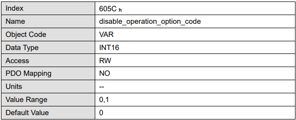
6.2.4 Disable_operation_option_code
The object disable_operation_option_code determines the behaviour if the state transition 5 (from OPERATION ENABLE to SWITCHED ON) will be executed.

6.2.5 Quick_stop_option_code
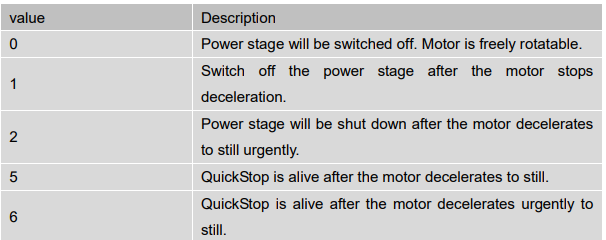
The object quick_stop_option_code determines the behaviour if a Quick Stop will be executed.
6.2.6 Halt_option_code
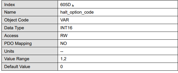
Halt_option_code determines how to stop when bit.8 (halt) of controlword is set to 1.

6.2.7 Fault_reaction_option_code
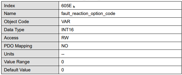
When an error is occurred, fault_reation_option_code determines how to stop.