
9. CAN communication example
The entire test below is based on three conditions:
1. Communication has been established correctly.
2. The address of the servo drive is 1.
3. All the message data is hexadecimal.
9.1 SDO configuration
SDO operation is to read and write parameters (0601h host sends 0581h slave sends)
Address: 3022h(Pn118). Write 1000. And then read this parameter.
Activate the downloading process: 2B,3022,00,03E8
That is …
601(ID) 2B 22 30 00 E8 03 00 00
The servo drive should respond 60,3022,00,00,00,00,00
That is 581(ID) 60 22 30 00 00 00 00 00
Activate the uploading: 40,3022,00,0000
That is 601(ID)40 22 30 00 00 00 00 00
The servo drive needs to respond: 43,3022,00,03E8
That is: 581 (ID) 43 22 30 00 E8 03 00 00
9.2 PDO configuration
RPDO mapping example: To configure two RPDO, one of which is 6040h and the other are 607A and 6081h) . The slaves respond of message 581h(ID) is omitted.
RPDO MAPPing
601 (ID)2F 00 16 00 00 00 00 00 //RPDO1 stop
First RPDO 201
601 (ID)23 00 16 01 10 00 40 60 //6040h
601(ID) 2F 00 16 00 01 00 00 00 // RPDO1 enable
601(ID) 2F 01 16 00 00 00 00 00 //RPDO2 stop
Second RPDO 301
601(ID) 23 01 16 01 20 00 7A 60 //607Ah and 6081h
601 (ID)23 01 16 02 20 00 81 60
601(ID) 2F 01 16 00 02 00 00 00// RPDO2 enable
And then set the transmit PDO as SYNC or Timing method. The default setting is Time method
After configuring the PDO, if you need to activate the configuration, you need to reset the communication. NMT is OPERATIONAL: 00 01 01//(the first “01” is the start node instruction,the second “01” is the number of the node)
Attention:
1.Before configuration, please stop PDO. For example, Cleaning the value with index 1600h and sub-index 00, cleaning the value to 0 is necessary). After configuration, please set a correct number of PDO( For example, set the value with index 1600h and sub-index 00 as 1) to activate the PDO.
2. Please pay attention to the data length and number. Wrong setting will lead to wrong configuration.
3. Please mapping time key object to PDO according to the actual needs to decrease bus load.
9.3 Profile position mode
At first, please mapping and configure PDO according to the example above and activate the communication.
And then, please set the control mode.
message:601(ID) 2F 60 60 00 01 00 00 00//set 6060h as 1(position contrl is PP)
And then, set status machine as Operation Enable
message:601(ID) 2B 40 60 00 06 00 00 00//set 6040h as 6,switch to “ready to switch on”
message:601(ID) 2B 40 60 00 07 00 00 00 //set 6040h as 7, switch to “switch on”
message:601(ID) 2B 40 60 00 0F 00 00 00 //set 6040h as F, switch to “operation enable” and servo on;
Note: this switching flow is based on successful switching received command and original state is “switch on disabled”. “status word” should be read in the practice.please refer to 6.1 State diagram (State machine), 6.2.1Controlword and 6.2.2 Statusword.
And then, send data by PDO
Let servo motor rotate for 5 revolutions ( Set PDO1 as 6040(status word), PDO2 as 607A(position pulse number) and 6081(velocity, unit as much as 0.1rpm)
Send RPDO2 The data is as below …
message:301 (ID) 50 C3 00 00 2C 01 00 00(50000,300)// 50 C3 00 00 is position data,that is, 50000 pulses;2C 01 00 00 is speed,that is, 30rpm;
Send RPDO1 as below
1、message:201(ID) 0F 00 //;Clear the bit4 of 6040 as 0.
2、message:201(ID) 1F 00 // Clear the bit4 of 6040 as 1 and servo motor is operating under absolute position; Motor runs.
3、message:201(ID) 0F 00 //Clear the bit4 of 6040.
4、message:201(ID) 5F 00 // Clear the bit4 of 6040 as 1. The servo motor runs under incremental position.
5、message:201(ID) 0F 00 //Clear bit4 of 6040 as 0.
Attention:
1) The servo drive is using ↑of 6040’s bit 4 to accept new position order. So after every single operation, the bit needs to be cleared. Host needs to check bit12 of status word 6040 in the servo drive to decide whether or not to give new data to servo systems. When status word 6041 in the servo drives 0, it means the servo drive is ready for new data and order. If the value is 1, the order won’t be executed even if there is data for the servo drive to receive.
2) In absolute approach, continuous position updating is required.
If you want to change the operating distance, you need to send RPDO2 again.
RPDO2:
301 B0 3C FF FF 2C 01 00 00 (-50000,-300)//That is, -50000 pulses; 30rpm.
9.4 Two-axis interplate position mode
At first, mapping and configure PDO
/receive 2 PDO by default:RPDO1:60C1h--01h
// Send two PDO by default:TPDO1:6041h TPDO2:6064h/606Ch
// pulse,Velocity 0.1rpm
Configure 1 RPDO
RPDO MAPPing
message:601(ID) 2F 00 16 00 00 00 00 00 //RPDO1 stop
message:601(ID) 23 00 16 01 20 01 C1 60 //60C1h,sub01
message:601(ID) 2F 00 16 00 01 00 00 00// RPDO1 enable
Configure 2 TPDO,TPDO1:6041h TPDO2:6064h/606Ch
TPDO MAPPing
message:601(ID) 2F 00 1A 00 00 00 00 00 //TPDO1 stop
message:601(ID) 23 00 1A 01 10 00 41 60 //6041h
message:601(ID) 2F 00 1A 00 01 00 00 00 // TPDO1 enable
message:601(ID) 2F 01 1A 00 00 00 00 00 //RPDO2 stop
message:601(ID) 23 01 1A 01 20 00 64 60 //6064h and 606Ch
message:601(ID) 23 01 1A 02 20 00 6C 60 //
message:601(ID) 2F 01 1A 00 02 00 00 00// TPDO2 enable
Set Sync time.
message:601(ID) 2F C2 60 01 10 00 00 00 //60C2h-01----->1ms,set according to the actual needs
message:601(ID) 2F C2 60 02 FD 00 00 00 //
Configure the PDO receiving and sending are both activated by one Sync frame.
Set 1400h
message:601(ID) 2F 00 14 02 01 00 00 00 //1400-02---->SYNC
Set 1800h
message:601(ID) 2F 00 18 02 01 00 00 00 //1800-02---->SYNC
Set 1801h
message:601(ID) 2F 01 18 02 01 00 00 00 //1801-02---->SYNC
Set control mode
message:601(ID) 2F 60 60 00 07 00 00 00//Set 6060h as7 ( IP position control)
And then, set the status machine
message:601(ID) 2B 40 60 00 06 00 00 00// Set 6040h as 6
message:601(ID) 2B 40 60 00 07 00 00 00 // Set 6040h as 7
message:601(ID) 2B 40 60 00 0F 00 00 00 // Set 6040h as F to servo on
message:601(ID) 2B 40 60 00 IF 00 00 00 // Set 6040h as1F to IP_ACTIVE status;
Activate the communicaiton
message:00(ID) 01 01
Setting the second axis is the same with the first axis.
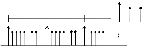
Host sends according to the setting of test SYNC cycle(1ms):
message:201(ID) 10 00 00 00 //16 P/R,interpolation potion data of the first axis
message:202(ID) 20 00 00 00 //32 P/R,interpolation potion data of the second axis
message:80(ID) // cycle to send SYNC according to interpolation cycle
And then,drive returns
message:181(ID) xx xx 00 00 //status word of the first axis
message:182(ID) xx xx xx xx //position and speed of the first axis
message:281(ID) xx xx 00 00 //status word of the second axis
message:282(ID) xx xx xx xx //position and speed of the second axis
Sequence diagram:
9.5 Homing
Set the control mode as homing control.
message:601(ID) 2F 60 60 00 06 00 00 00// Set the control mode as homing control.
message:601(ID) 2F 98 60 00 04 00 00 00//Use the fourth way to set the homing mode.
Set the status machine
message:601(ID) 2B 40 60 00 06 00 00 00
message:601(ID) 2B 40 60 00 07 00 00 00
message:601(ID) 2B 40 60 00 0F 00 00 00 //Servo On
Send data through PDO. ( Set PDO1 as 6040( status word). Set PDO2 as 607A( Position pulse number) and 6081. ( Speed, unit 0.1rpm)
Set the homing method as 10rpm.
message:601(ID) 23 99 60 02 64 00 00 00
Homing is started.
message:201 (ID) 1F 00
Cancel homing.
message:201 (ID) 0F 00