10. Alarm Displays
10.1 Alarm Classifications
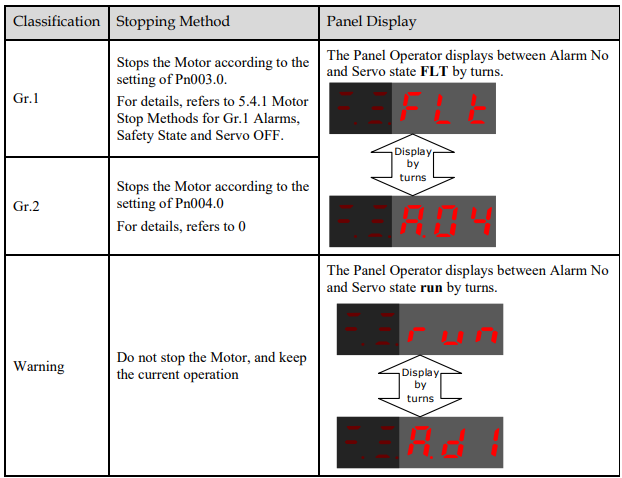
There are three classifications of alarms for the Drive: Gr.1, Gr.2, and Warning. They will affect the display and operation for the Servo System.
10.2 Alarm Detailed
10.2.1 Gr.1 Warning
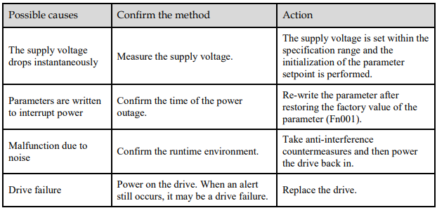
A.01:Parameter destruction
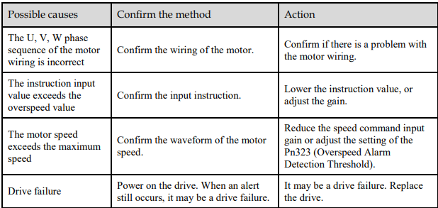
A.03:Motor overspeed
A.04:Overload
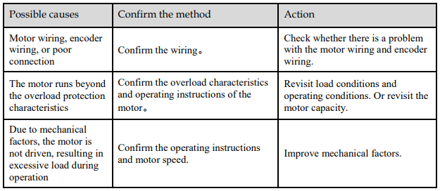

A.05:The position deviation counter overflows
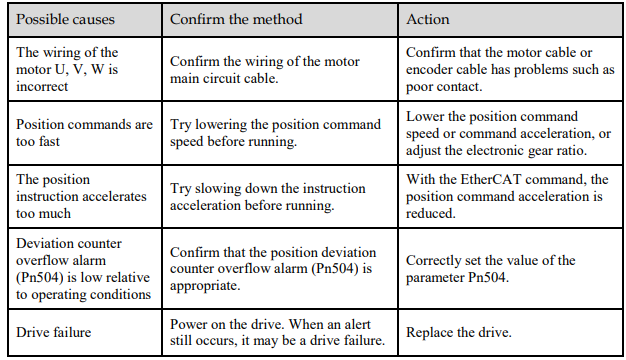
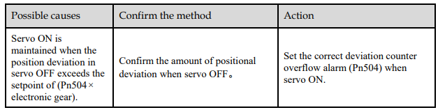
A.06:The position deviation pulse overflows
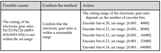
A.07:The electronic gear setting or pulse frequency is unreasonable
A.08:There is a problem with the first channel of current detection

A.09:There is a problem with the second channel of current detection

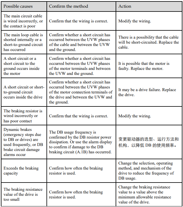
A.12:Overcurrent
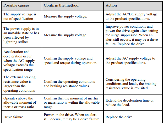
A.13:Overvoltage
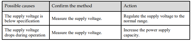
A.14:Undervoltage
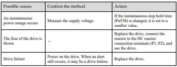
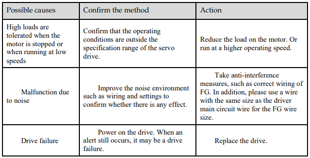
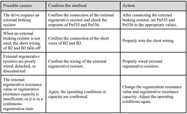
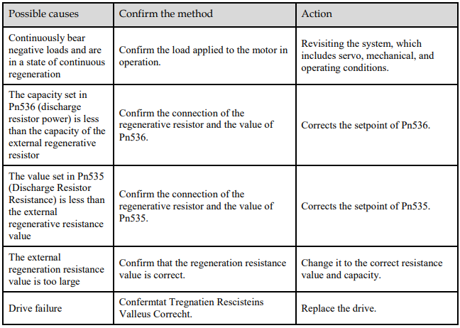
A.16:Regeneration abnormalities
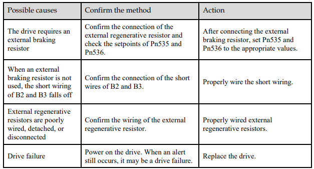
A.18:The module is overheating
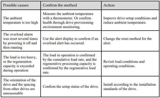

A.1D:The temperature sensor is disconnected
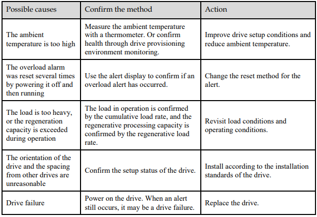
A.1E:The main charge circuit is faulty
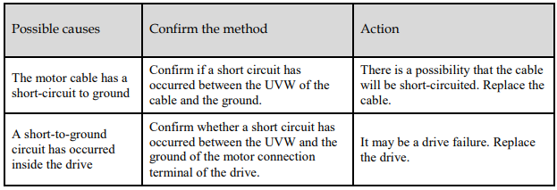
A.1F:Short-to-ground fault
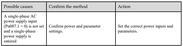
A.24:The main loop power supply is wired incorrectly
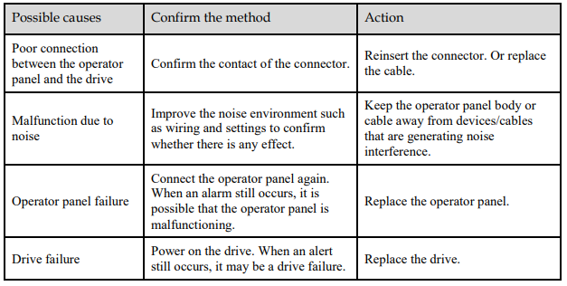
A.37:Control panel communication timed out
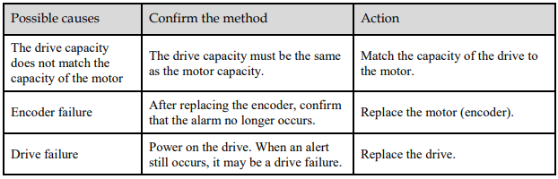
A.42:The motor power does not match the drive power
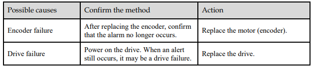
A.43:The encoder type is incorrect
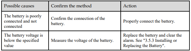
A.45:Multi-turn data error

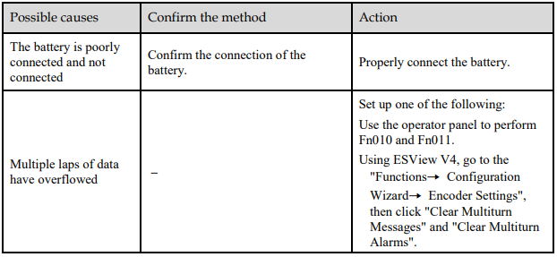
A.46:Multi-turn data overflow
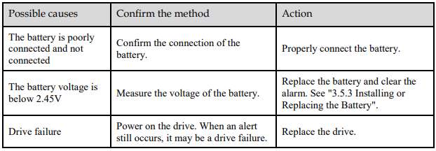
A.47:The absolute encoder battery voltage is too low
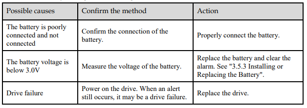
A.48:Absolute encoder battery voltage undervoltage
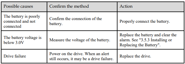
A.49:Multiple or singleturn data anomalies were detected
A.50:The encoder is disconnected
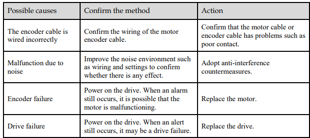
A.51:Absolute encoder overspeed detection
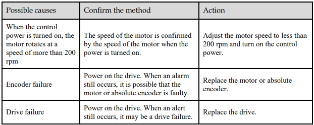
A.52:An error occurred inside the encoder
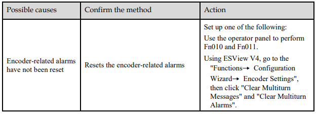
A.53:Error encoder lap information
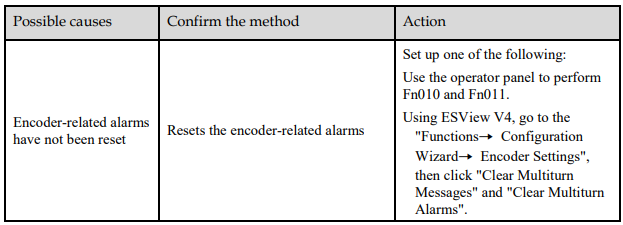
A.54:Errors occurred at the check digits and cutoff bits in the encoder control domain
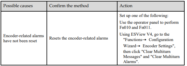
A.58:Information such as encoder zone phase is empty or incorrect

A.59:Information such as the motor body in the second area of the encoder is empty or wrong

A.65:Location overflow alarm
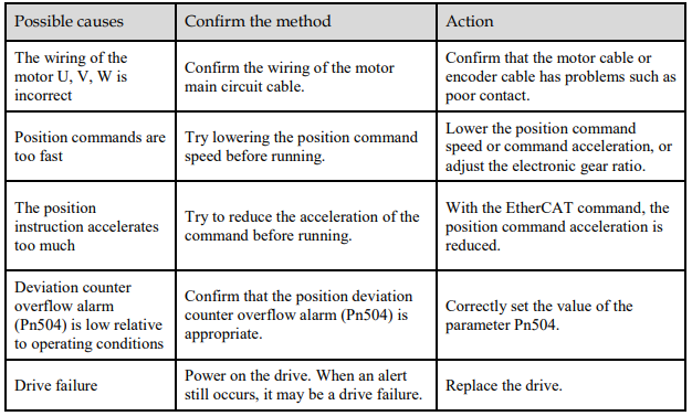
A.70:DC synchronization error

A.71:SM Event synchronization event premature
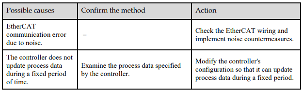
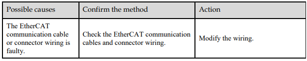
A.72:SM Event synchronization event timed out
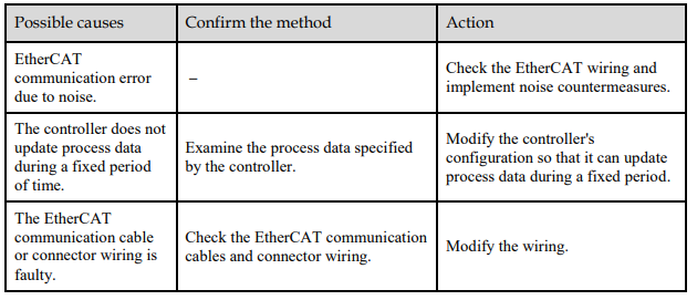
A.73:EtherCAT processor internal error

A.74:The position is set in the Cubic interpolation algorithm with a period error

A.75:There was an error setting for the synchronization period
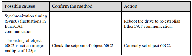
A.76:The acceleration object is set to 0 in PP/PV mode

A.77:OP mode process data watchdog communication timed out
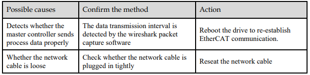
A.81:The motor UVW wiring is wrong
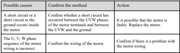
A.82:The motor type does not match

A.83:The motor is operating abnormally


A.F0:Internal logic exceptions

Gr.2 Alarm
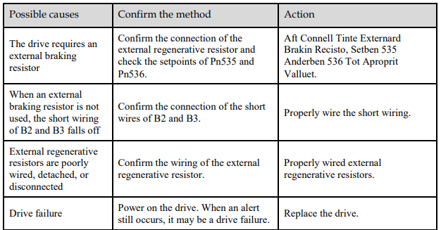
A.15:The regenerative resistance is damaged
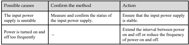
A.1A:The charging resistance is overloaded
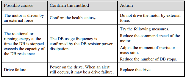
A.1B:The DB braking circuit is damaged
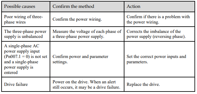
A.20:The main loop power line is out of phase
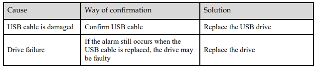
A.33: USB Power Supply Exceptions
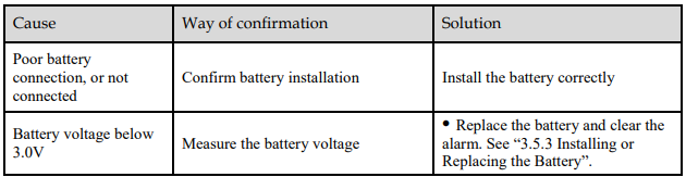
A.49: Multi-turn or Single-turn Data Exception Detected

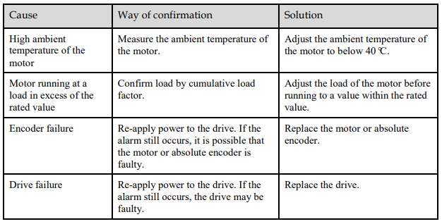
A.4A: Excessive Encoder Temperature
10.2.3 Warnings
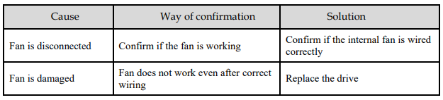
A.1C: Fan Disconnection Alarm
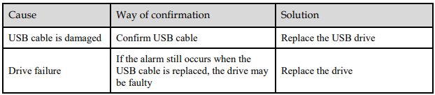
A.33: USB Power Supply Exceptions
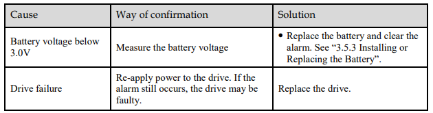
A.49: Multi-turn or Single-turn Data Exception Detected

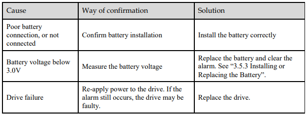
A.4B: Absolute Encoder Battery Undervoltage (Tamagawa)
A.D5: Fan Disconnection Warning

A.D7: Warning for Reaching Soft Limit Positive Limit

A.D8: Warning for Reaching Soft Limit Reverse Limit

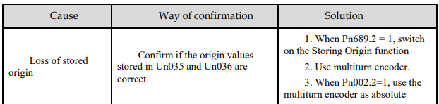
A.D9: Origin Error Warning