
4. Basic Settings
You can implement the functions of parameter setting, display, monitoring, alarm, adjustment, etc. of the Drive in the following two ways.
Use the Panel Operator of the Drive
Use the ESView V4 (Recommended)
4.1 BasicPanel OperationOperator
4.1.1 Key Names and Functions on Panel Operator
The panel operatorThere is a built-inPanel operator that consists of display section and keys locatedOperator on the front panel of the servoDrive, drive.as is shown in Figure 4-1.ParameterFigure setting,4-1 status display ,and executionDiagram of utilityPanel functionOperator
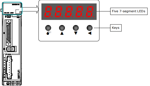
The names and functions of the keys on the panelPanel operatorOperator are shown as follows:follows
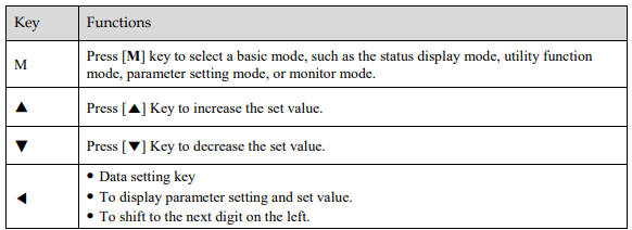
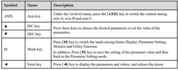
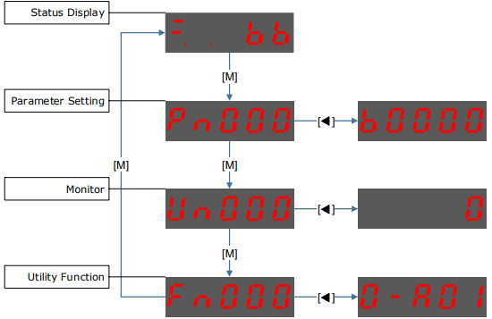
4.1.2 AxisBasic SwitchingMode SelectionSinceThe thebasic Servodrivemodes onlyinclude: canStatus setDisplay Mode, Parameter Setting Mode, Utility Function Mode, and monitorMonitor only one axis atMode.
Select a time,basic themode use can press thewith [AXIS]M] key to switchdisplay the controloperation intostatus, anotherset axis.parameters Theand indicatoroperation lampreferences, behind each axis can show the work status: Lit indicates the axisas is controlled at present. Not lit indicates the axis is not controlled at present. Blinking indicates an alarm occurredshown in theFigure axis4-2.
Figure not4-2 controlledSelect ata present.
basic mode
4.1.3 Status Display Mode SwitchingAsPower ON the Drive and wait for a while, the Panel Operator will initially display the Servo Status.
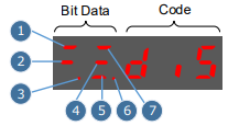
The information displayed by the status is showndivided ininto two parts asFigure 4-3:
The first two digits are called Bit Data, what indicates the followingsignal figure,states press [M] key can switchduring the modeoperation amongof Drive.
The last three digits are called Code, what indicates the operation states of Driv.
Figure 4-3 Status Display, Parameter Setting, Monitor and Utility Function in turns. Display
Note: Only under the 1st-level menu, press the [AXIS] key to switch the control among axis-A, axis-B and axis-C.
4.2 Status DisplayThe status display mode displays the servo drive status as bit data and codes.The status display mode is selected when the power supply is turned ON. If it is not displayed, select this mode by pressing [M] key.Note that the display differs between the speed/torque control and position control.
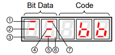
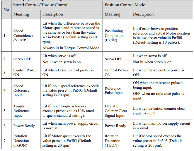
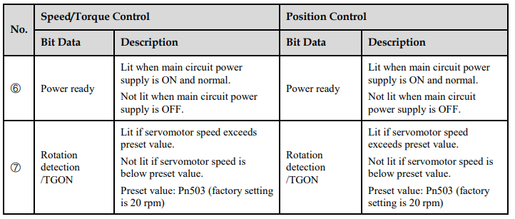
The followingdisplay table lists the descriptionmeaning of each bitsegment dataon Bit Data are shown in speed/torqueTable control4-1 , and positionthey control.have different meanings under Speed or Torque Control Mode and Position Control Mode
Table 4-1 Display meaning of each segment on Bit Data
The followingdisplay table lists the descriptionmeanings of code.Code are shown inTable 4-2.
Table 4-2 Display meanings of Code
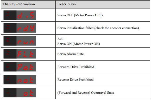

NOTE: When the Drive is in Servo Alarm State, you shall check and correct the fault according to the Alarm Number Display, and then, you can press [◄] key to try to clear the current alarm.
4.3 Operation in1.4 Parameter Setting ModeThe servo drive offers a large number of functions, whichFunctions can be selected or adjusted by setting parameters. There are two types of parameters.
Function Parameters: the functions allocated to each digit of the Panel Operator can be selected.
Adjustment Parameters: a parameter is set to a value within the specified range of the parameter.
For a description of the parameter settings.settings, Forplease detailsrefer about each parameters description seeto the section AppendixChapter A11Parameters.
Function Parameters List.Settin
The following procedure is an example below shows how to change parameter Pn003 (Application Function Selections 3) from 0000 to 1032.
Step 1 Press [M] key several times to select the Parameter Setting Mode.

Step 2 Press [▲] key or [▼] key to select the parameter Pn003.
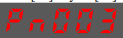
Step 3 Press [◄] key to display the current value of Pn003.
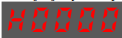
Step 4 Press and hold [◄] key for 1 second or more, and then a flashing decimal point will appear at the bottom right of the 5th digit.

Step 5 Press [▲] key twice, changing the settingvalue of the 5th digit from 0 to 2.
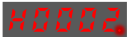
Step 6 Press [◄] key once, moving the flashing decimal point to the 4th digit.

Step 7 Press [▲] key three times, changing the value of the 4th digit from 0 to 3.
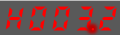
Step 8 Press [◄] key twice, moving the flashing decimal point to the 2nd digit.
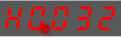
Step 9 Press [▲] key once, changing the value of the 2nd digit from 0 to 1.

Step 10 Press the [M] key once to return to the display of Pn003 parameter value.
Step 11 Press the [M] key once to display parameter Pn003.
NOTE
After completing the function parameters setting, restart the Drive to take effect.
----End
Adjustment Parameters Setting
The example below shows how to change parameter Pn102 (Speed Loop Gain) from 100 to 85.
Step 1 Press [M] key for several times to switchselect intothe Parameter Setting mode, after turning the Servodrive ON.Mode.
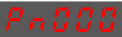
Step 2 Press [▲] key or [▼] key to select the parameter Pn102.

Note: press and hold [▲] key or [▼] key to jump the parameter number quickly.
Step 3 Press [◄] key to display the current value of Pn102Pn102.

Step 4 Press [▼▲] key or [▼] key to change the value to 00085.
Press and hold [▼▲] key or [▼] key to jump the setting value quickly.

Step 5 Press [◄] key or [M] key to return to the display of thePn102.
---- current parameter.End
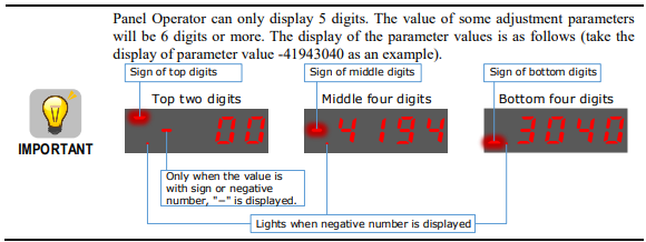
The example below shows how to change parameter Pn504 (Deviation Counter Overflow Alarm) from 41943040 to 42943240.
Step 6 Press [M] key several times to select the Parameter Setting Mode.

Step 7 Press [▲] key or [▼] key to select the parameter Pn504.
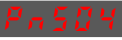
Step 8 Press [◄] key to display bottom four digits of the current value of Pn504.

Step 9 Press and hold [◄] key for 1 second or more, and then a flashing decimal point will appear at the bottom right of the 5th digit.

Step 10 Press [◄] key twice, moving the flashing decimal point to the 3rd digit.
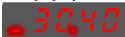
Step 11 Press [▲] key twice, changing the value of the 3rd digit from 0 to 2.

Step 12 Press [◄] key four times, moving the flashing decimal point to the 3rd of middle four digits.
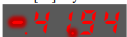
Step 13 Press [▲] key once, changing the value of the 3rd digit from 1 to 2.
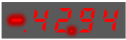
Step 14 Press the [M] key once to return to the display of Pn504 parameter value.
Step 15 Press the [M] key once to display parameter Pn504.
---- End
4.4 Operation in1.5 Monitor Mode
The monitorMonitor modeMode allowscan be used for monitoring the reference values input into the servo drive,values, I/O signal status, and servo driveDrive internal statusstatus.
The toMonitor Mode can be monitored.selected during Motor operation.
Using theSelect Monitor Mode
The example below shows how to displaydisplay, the valuecontents of monitor number Un003 (1500)when storedthe inMotor Un001.rotates at 100 ).
Step 1 Press [M] key for several times to switch into Parameter Setting mode, after turningselect the ServodriveMonitor ON.Mode.
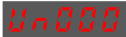
Step 2 Press [▲] key or [▼] key to select the monitor number Un001.Un003.
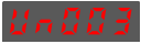
Step 3 Press [◄] key to display the current valuedata of Un001.Un003.
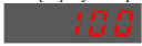
Step 4 Press [◄] key again to return to the display of the current monitor number.
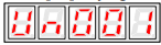
Un003.
---- End
DescriptionsContents of Monitor NumberMode Displa
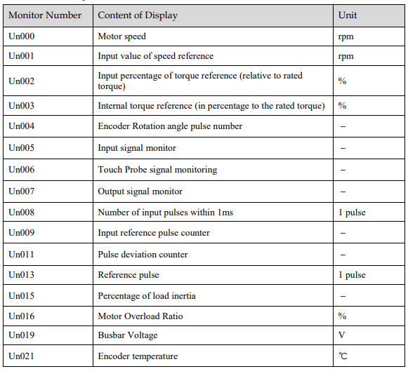

InThe which,status the(low displaylevel meaningor high level) of Un005,input Un006signal andallocated Un007to areeach showninput asterminal followingis table. displayed.
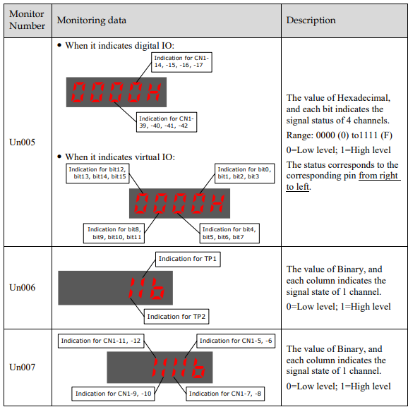
NOTE: Un007 represents the state of the output signal. The optocoupler ON and OFF of each output signal depends on whether the output signal is inverted:
If the signal is not inverted, lit for turning the optocoupler ON, and not lit for turning the optocoupler OFF.
If the signal is inverted, lit for turning the optocoupler OFF, and not lit for turning the optocoupler ON.
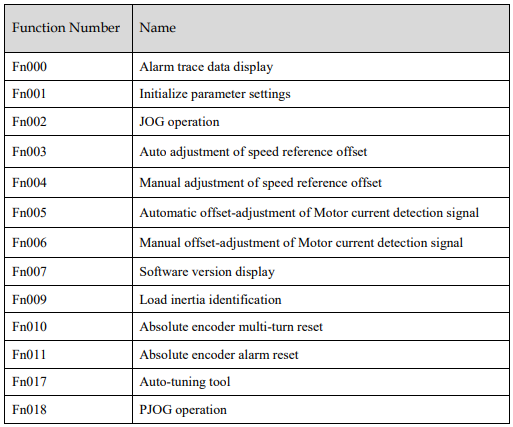
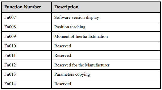
4.5 Operation in1.6 Utility Function ModeInThis utilitysection functiondescribes mode,how to apply the panelbasic operatoroperations canusing bethe usedPanel Operator to run and adjust the servo drive and servomotor.Motor.
The following table listsshows the functionsparameters in the utilityUtility functionFunction mode.Mode.
4.5.1 (Alarm Tracebacktrace Datadata Displaydisplay)
The alarm tracebacktrace data display can display up to 10ten previously occurred alarms. The alarmfollowing isare displayedthe onsteps Fn000,to which is stored indisplay the alarm tracebacktrace data.
Follow the procedures below to confirm alarms which have been generated.
Step 1 Press [M] key for several times to switchselect intothe Utility Function mode,Mode.
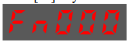
Step 2 Press [▲] key or [▼] key to select the function number Fn000.
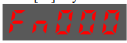
Step 3 Press [◄] key to display the latest alarm number.

Step 4 Press [▲] key or [▼] key to displayview anotherthe other alarm numbers occurred recently.data.
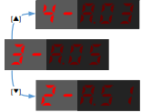
Step 5 Press the [◄] key to return to the display of the currentFn000.
Press functionand number.
[◄] key for 1 second or more to clear all the alarm trace data.
----End
4.5.2Fn001 Parameter(Initialize Settingsparameter Initializationsettings)FollowThe following are the procedures belowsteps to perform theinitialize parameter settings initialization.settings.
Step 1 Press [M] key for several times to switchselect intothe Utility Function mode,Mode.
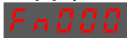
Step 2 Press [▲] key or [▼] key to select the function number Fn001.
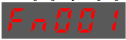
Step 3 Press [◄] keykey, toand preparePanel forOperator initializingdisplays theas parameter settings.Initialize the parameter settings of axis-Abelow.
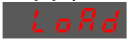
Initialize the parameter settings of axis-B
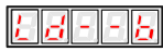
Initialize the parameter settings of axis-C

Step 4 Press and hold [◄] key for 1 second orto moreinitialize the parameter settings, until “done”Panel isOperator displayeddisplays and blinked,blinks done, which indicates the initialization of parameter settings initializationsetting has been completed.

Step 5 RelaseRelease [◄] key to return to the display of the current function number.

----End
4.5.3 JOG OperationFollow the procedures below to operate the Servomotor in JOG.Step 1 Press [M] key for several times to switch into Utility Function mode, after turning the servo ON.Step 2 Press [▲] key or [▼] key to select the function number Fn002.
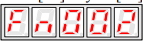
Step 3 Press [◄] key to enter the JOG running mode.
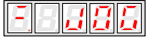
Step 4 Press [M] key to turn ON the servo.Here, you can press [M] key to turn ON or turn OFF the servo. However, Turn ON the servo if you want to run the Servomotor.Step 5 Press [▲] key or [▼] key to run the Servomotor forward or reverse in a certain amount of movement. Press and hold [▲] key or [▼] key to run the Servomotor continuously.

NOTE: the rotation direction of the Servomotor depends on the setting of Pn001.0. The above figure shows the default setting.Step 6 Relase [◄] key to return to the display of the current function number. Moreover, the servo is turned OFF automatically.Fn001.
----End
4.5.4Fn002 Offset(JOG operation)
This utility function often used for trial operation, refers to the section 7.3.3 JOG Operation
Fn003 (Auto Adjustment forof CurrentSpeed DetectionReference Offset) SinceFor speed control, even if the Offsetspeed reference is 0V (command reference is 0 or stopped), the servo motor may move at a very low speed. By this moment, use the offset adjustment function to clear the offset. Refer to "5.9.2 Adjustment forof CurrentSpeed DetectionReference Offset".
Fn004 (Manual Adjustment of Speed Reference Offset)
Refer to "5.9.2 Adjustment of Speed Reference Offset" when using the Manual Adjustment of Speed Reference Offset.
Fn005 (Automatic offset-adjustment of Motor current detection signal)
Motor current detection offset adjustment has beenperformed performedat ESTUN before theshipping. device leaves the factory,Basically, the user doesneed not need to perform this operationadjustment. generally.However,

The forfollowing Current Detection shall be peformmed whenare the torque ripple was too large or if you wantsteps to further reduce the torque ripple.This section describesexecute the automatic and manual offset adjustment for current detection.

Automatic Adjustment
Following the below procedure to perform the automatic adjustment.
Step 1 Press [M] key for several times to switchselect intothe Utility Function mode,Mode.
turning
Step 2 Press [▲] key or [▼] key to select the function number Fn005.
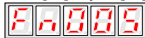
Step 3 Press [◄] keykey, toand preparePanel forOperator performingdisplays theas automatic adjustment.below.
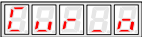
Step 4 Press and hold [M] key forto 1 second or more until “done” is displayed and blinked, which indicatesexecute the automatic adjustmentoffset hasadjustment.Panel beenOperator completed.
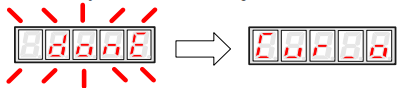
blinks done, and 2 seconds later, it will return to previous display.
Step 5 Press the [◄] key to return to the display of the current function number.Fn005.
---- End
Manual AdjustmentFollowing the below procedure to perform the manual adjustment.Step 1 Press [M] key for several times to switch into Utility Function mode, after turning the servo ON.Step 2 Press [▲] key or [▼] key to select the function number Fn006.
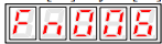
Step 3 Press [◄] key to prepare for performing the manual adjustment.
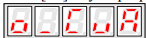
Step 4 Press [M] key to select the desired setting phase between phase-U (o_CuA) and phase-V (1_Cub).

Step 5 Press and hold [◄] key for 1 second, the detection value of current phase is displayed.

Step 6 Press [▲] key or [▼] key to change the value for the adjustment.

Step 7 Press and hold [◄] key for 1 second to return to the setting phase.
Step 8 Press [◄] key to return to the display of the current function number.

----End
4.5.5 Software Version DisplayFollowing the below procedure to perform the Software Version Display.
Step 1 Press [M] key for several times to switch into Utility Function mode, after turning the servo ON.Step 2 Press [▲] key or [▼] key to select the function number Fn007.
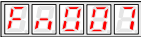
Step 3 Press [◄] key to display the version of DSP software. (The leftmost bit is t).

Step 4 Press [M] key to display the version of FPGA/CPLD software. (The leftmost bit is P).
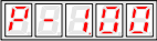
Step 5 Press [M] key to return to the version of DSP software displayed.Step 6 Press [◄] key to return to the display of the current function number.----End
4.5.6 Position Teaching FunctionFollowing the below procedure to perform the postion teaching.Step 1 Press [M] key for several times to switch into Utility Function mode, after turning the servo ON.Step 2 Press [▲] key or [▼] key to select the function number Fn008.
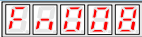
Step 3 Press [◄] key to prepare for the position teaching.
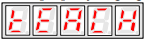
Step 4 Press and hold [◄] key for 1 second or more until “done” is displayed and blinked, which indicates the position teaching has been completed.
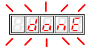
Step 5 Relase [◄] key to return to the display of the current function number.----End
4.5.7 Moment of Inertia EstimationFollowing the below procedure to perform the Moment of Inertia Estimation.Step 1 Press [M] key for several times to switch into Utility Function mode, after turning the servo ON.Step 2 Press [▲] key or [▼] key to select the function number Fn009.
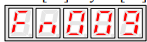
Step 3 Press [◄] key to prepare for the Moment of Inertia Estimation.
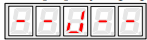
Step 4 Press [M] key for performing the operation.The real-time rotational speed of the Servomotor is displayed.Step 5 When the Servomotor is stopped, the estimation value is displayed on the panel operator, and its unit is kg.cm2.

----End
4.5.8 Parameters CopyingFollowing the below procedure to perform the Parameters Copying.Step 1 Press [M] key for several times to switch into Utility Function mode, after turning the servo ON.Step 2 Press [▲] key or [▼] key to select the function number Fn013.
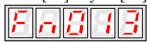
Step 3 Press [◄] key to prepare for the parameters copying.
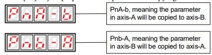
The meaning of the other displays are similar to the above.Step 4 Press and hold [◄] key for 1 second or more until “done” is displayed and blinked, which indicates the parameter copying has been completed.
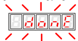
Step 5 Relase [◄] key to return to the display of the current function number.----End