5. Application Functions
5.1 Trial Operation5.1.1 Flow of Trial OperationMake sure that all the wiring has been completed before the trial operation.Perform the following three methods of trial operation in order. Instructions are given for speed control mode (standard setting) and position control mode. Unless otherwise specified, the standard parameters for speed control mode (factory settings) are used.
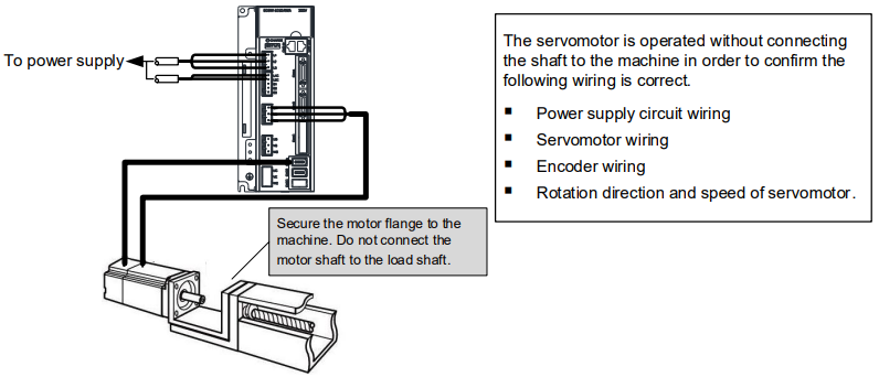
Trial Operation for Servomotor Without Load
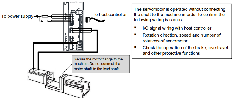
Trial operation for servomotor with host reference
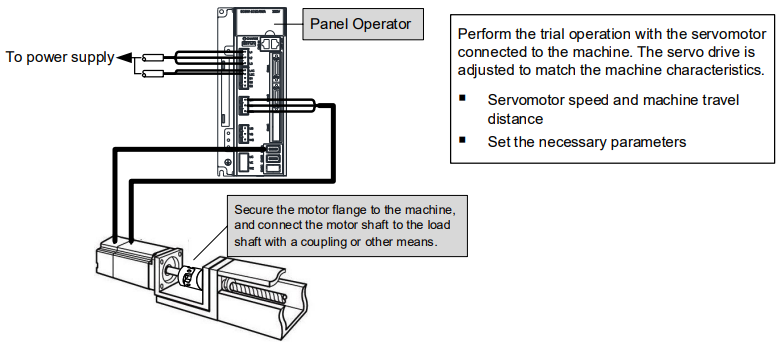
Trial operation for servomotor and machine combined
Procedure for the trial operationStep 1 InstallationInstall the servomotor and servo drive according to the installation conditions. (Do not connect the servomotor to the machine because the servomotor will be operated first under the no-load condition for checking.)Step 2 WiringConnect the power supply circuit (L1, L2 and L3), servomotor wiring (U, V, W), I/O signal wiring (CN1 □), and encoder wiring (CN2□). But during Trial Operation for Servomotor Without Load, disconnect the CN1□ connector.Step 3 Turn the power ONTurn the power ON. Using the panel operator to make sure that the servo drive is running normally. If using a servomotor equipped with an absolute encoder, please perform the setup for the absolute encoder.Step 4 Perform the JOG operationPerform the JOG operation with the servomotor alone under the no-load condition.Step 5 Connect input signalsConnect the input signals (CN1□) necessary for trial operation to the Servodrive.Step 6 Check input signalsUse the internal monitor function to check the input signals. Turn the power ON, and check the emergency stop, brake, overtravel, and other protective functions for the correct operation.Step 7 Input the Servo-ON signalInput the Servo-ON signal, and turn ON the servomotor.Step 8 Input referenceInput the reference necessary for control mode, and check the servomotor for correct operation.Step 9 Protective operationTurn the power OFF, and connect the servomotor to the machine. If using a servomotor equipped with an absolute encoder, set up the absolute encoder and make the initial settings for the host controller to match the machine’s zero position.Step 10 Set necessary parametersUsing the same procedure as you did to input a reference in step 8,operate the servomotor via the host controller and set the parameter to make sure the machine’s travel direction, travel distance, and travel speed allcorrespond to the reference.Step 11 RunThe servomotor can now be operated. Adjust the servo gain if necessary.----End
5.1.2 Trial Operation for Servomotor Without Load

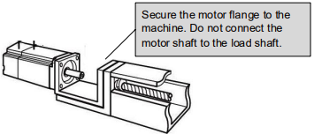
In this section, confirm the cable connections of the main circuit power supply, servomotor and encoder.Incorrect wiring is generally the reason why servomotors fail to operate properly during the trial operation.Confirm the wiring, and then conduct the trial operation for servomotor without load according to the following steps.Step 1 Secure the servomotor. Secure the servomotor flange to the machine in order to prevent the servomotor frommoving during the operation. Do not connect the servomotor shaft to the machine. The servomotor may tip over during rotation.
Step 2 Check the power supply circuit, servomotor, and encoder wiring.With the I/O signal connector (CN1□) disconnected, check the power supply circuit and Servomotor wiring.See the section 3.1 Main Circuit Wiring for the details about the wiring of the main circuit.
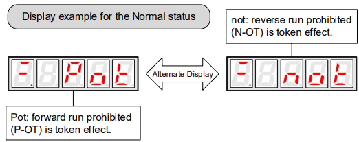
Step 3 Turn ON the control power supply and main circuit power supply.If the power is correctly supplied, the panel operator display on the front panel of the Servodrive will appear as shown on the left. The display on the left indicates that forward run prohibited (P-OT) and reverse run prohibited (N-OT).
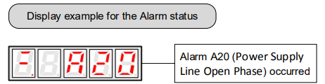
If an alarm display appears, the power supply circuit, servomotor wiring, or encoder wiring is incorrect. If an alarm is displayed, turn OFF the power, find the problem, and correct it.
Step 4 When using a servomotor with a brake, release the brake first before driving the servomotor.Step 5 Use the panel operator to operate the servomotor with utility function Fn002 (JOG Operation). Check the Servomotor rotates in the forward direction by pressing [▲] key, and reverse direction by pressing [▼] key.The operation is completed when the operation is performed as described below and no alarm occurs.Complete the Fn002 (JOG Mode Operation) and turn OFF the power.The servomotor speed can be changed using the Pn305 (JOG Speed). The factory setting for JOG speed is 500 rpm.

You can operate the panel operator instead of the host controller for Jog operation of the Servomotor.Moreover, the signal of P-OT and N-OT are invalid during the Jog operation.----End
5.1.3 Trial Operation for Servomotor without Load from Host ControllerCheck that the servomotor move reference or I/O signals are correctly set from the host controller to the servo drive.Also check the wiring and polarity between the host controller and servo drive, and the servo drive operation settings are correct. This is the final check before connecting the servomotor to the machine.
Operating Procedure in Position Control Mode (Pn005=H――1-)The following circuits are required: External input signal circuit or equivalent.
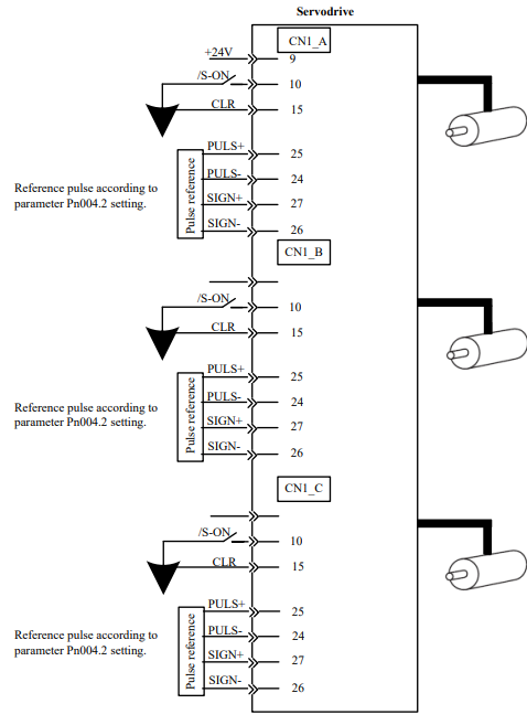
Step 1 Match the reference pulse form with the pulse output form from the host controller. Set the reference pulse form with Pn004.2.Step 2 Set the reference unit and electronic gear ratio so that it coincides with the host controller setting. Set the electronic gear ratio with Pn201 (or Pn203)/Pn202.Step 3 Turn the power and the servo ON input signal ON.Step 4 Send the slow speed pulse reference for the number of servomotor rotation easy to check (for example, one servomotor revolution) from the host controller in advance. Set the servomotor speed to100rpm for the reference pulse speedbecause such speed is safe.Step 5 Check the number of reference pulses input to the servo drive by the changed amount before and after the Un013 and Un014 (input reference pulsecounter)[pulse] were executed. See the section 4.4 Operation in Monitor for the details about how it is displayed.Step 6 Check whether the actual number of servomotor rotations Un009, Un010 coincides with the number of input reference pulses. See the section 4.4 Operation in Monitor for the details about how it is displayed.Step 7 Check that the servomotor rotation direction is the same as the reference. Check the input pulse polarity and input reference pulse form.Step 8 Input the pulse reference with the large number of servomotor rotation from the host controller to obtain the constant speed. Set the servomotor speed to 100rpm for the reference pulse speed because such speed is safe.Step 9 Check the reference pulse speed input to the servo drive using the Un008in Monitor Mode.(input reference pulse speed)[rpm]. See the section 4.4 Operation in Monitor for the details about how it is displayed.Step 10 Check the servomotor speed using the Un000 in Monitor Mode. (servomotor speed) [rpm]. See the section 4.4 Operation in Monitor for the details about how it is displayed.Step 11 Check the rotation of the Servomotor. To change the servomotor rotation direction without changing the input reference pulse form, see the section 5.3.2 Rotation Direction. Perform the operation from step 8 again after the servomotor rotation direction is changed.Step 12 When the pulse reference input is stopped and servo OFF status is entered, the trial operation for servomotor without load in position control mode is complete.----End
5.1.4 Trial Operation with the Servomotor Connected to the Machine

Follow the procedure below to perform the trial operation.Step 1 Turn the power ON, and make the settings for the mechanical configuration related to protective functions such as overtravel and brake. See the section 5.3 Basic Funtions Setting.When a servomotor with brake is used, take advance measures to prevent vibration due to gravity acting on the machine or external forces before checking the brake operation. Check that both servomotor and brake operations are correct.Step 2 Set the necessary parameters for the control mode used. Refer to the sections 5.5 Speed Control and 5.6 Position Control according to the control method.Step 3 Connect the servomotor to the machine with the coupling,etc.,while the power is OFF.Step 4 Check that the servo drive is servo OFF status and then turn ON the power to the machine (host controller). Check again that the protective function in step 1 operates normally. See the section 5.3 Basic Funtions Setting. For the following steps, take advanced measures for an emergency stop so that the servomotor can stop safely when an error occurs during operation.Step 5 Perform trial operation with the servomotor connected to the machine, following each section in 5.1.2 Trial Operation for Servomotor Without Load. Check that the trial operation is completed according to the trial operation for servomotor without load. Also, check the settings for machine such as reference unit.Step 6 Check the parameter settings for control mode used in step 2. Check that the servomotor rotates matching the machine operating specifications.Step 7 Adjust the servo gain and improve the servomotor response characteristics, if necessary. The servomotor will not be broken in completely during trial operation. Therefore, let the system run for a sufficient amount of time to ensure that it is properly broken in.----End
5.1.5 Trial Operation for Servomotor with BrakesHolding brake operation of the servomotor can be controlled with the brake interlock output (/BK) signal of the servo drive.When checking the brake operation,take advance measures to prevent vibration due to gravity acting on the machine or external forces. Check the servomotor operation and holding brake operation with the servomotor separated from the machine.If both operations are correct, connect the servomotor to the machine and perform trial operation.
5.2 Control Method SettingThe control modes supported by the ED3M series Servodrives are described below.
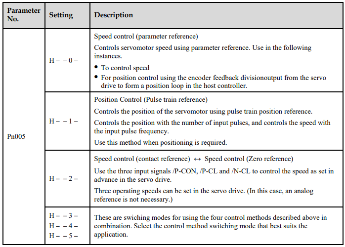
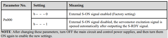
5.3 Basic Funtions Setting5.3.1 Servo ONThis sets the servo ON signal (/S-ON) that determines whether the Servomotor power is ON or OFF.
/S-ON Signal


/S-ON SelectionA parameter can be always used to set the servo ON condition. This eliminates the need to wire /S-ON, but care must be taken because the servo drive can operate as soon as the power is turned ON.
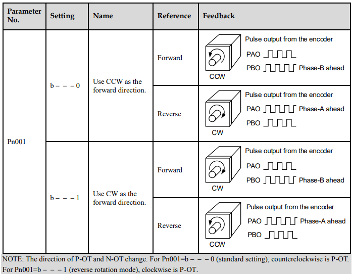
5.3.2 Rotation DirectionThe rotation direction of the servomotor can be switched without changing the reference pulse to the servo drive or the reference voltage polarity.This causes the rotation the servo motor shaft is rotating to change. The output signal polarity, such as the encoder pulse output and the analog monitor signal from the servo drive do not change.The standard setting for “forward rotation” is counterclockwise as viewed from the servomotor load end.
5.3.3 OvertravelThe overtravel limit function forces movable machine parts to stop if they exceed the allowable range of motion and turn ON a limit switch.
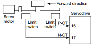
Overtravel ConnectionTo use the overtravel function, connect the following overtravel limit switch to the corresponding pin number of servo drive CN1□ connector correctly.
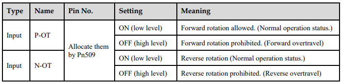
Connect limit switches as shown below to prevent damage to the devices during linear motion.Rotation in the opposite direction is possible during overtravel.For example, reverse rotation is possible during forward overtravel.

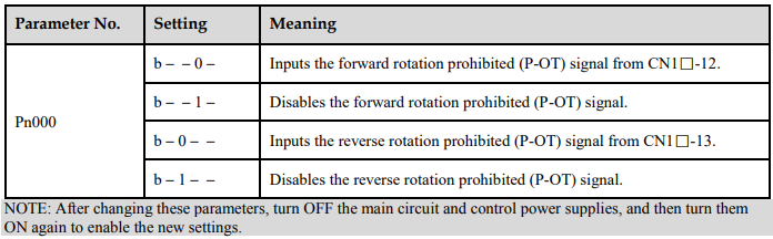
Overtravel SelectionA parameter can be set to disable the overtravel signal. If the parameter is set, there is no need to wire the overtravel input signal.
Stop MethodThis is used to set the stop method when an overtravel(P-OT,N-OT)signal is input while theservomotor is operating.
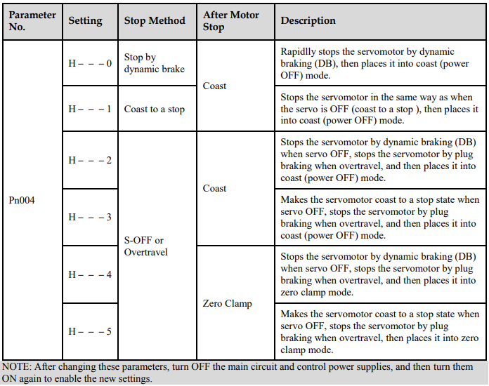

Dynamic brake is an emergency stop function, and one of the general methods to cause a servomotor sudden stop.Dynamic brake suddenly stops a servomotor by shorting its electrical circuit.If the servomotor is frequently started and stopped by turning the power ON/OFF or using the servo ON signal(/S-ON), the DB circuit will also be repeatedly operated, degrading the servo drive’s internal elements.Use the speed input reference and position reference to control the starting and the stopping of the servomotor.
Stop Torque for Overtravel


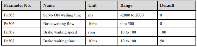
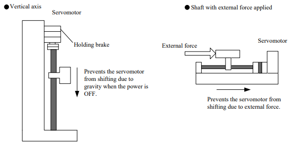
5.3.4 Holding Brakes SettingThe holding brake is used when the servo drive controls a vertical axis.A servomotor with the brake option helps prevent movable parts from shifting due to gravity when power is removed from the servo drive.(Refer to the section 5.1.5 Trial Operation for Servomotor with Brakes.)

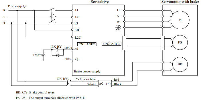
Wiring ExampleUse the servo drive sequence output signal /BK and the brake power supply to form a brake ON/OFFcircuit. The following diagram shows a standard wiring example.
Brake interlock output
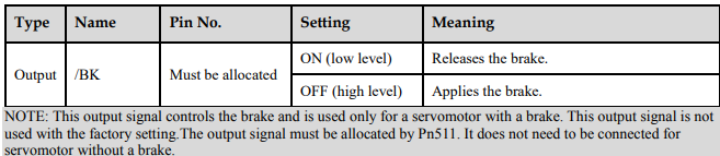
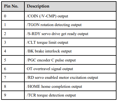
/BK AllocationBrake interlock output (/BK) is not used with the factory setting.The output signal must be allocated.
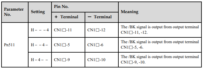

Parameter Pn511 description is as following: