
5. Application Functions
5.1 Power Supply
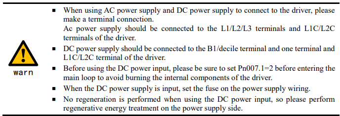
The main circuit and control circuit of the Drive can be operated with AC power input. When AC power input is selected, single- phase or three phase power input can be used. You shall to set the parameter Pn007.1 and Pn007.3 (use AC power input) according to the applicable power supply.
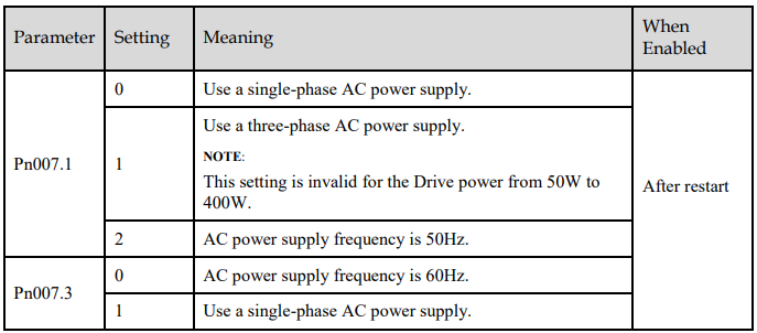
An alarm A.24 (Main Circuit Power Supply Wiring Error) may be occurred if the setting of Pn007.1 be consonant with not match the applicable power supply
5.2 Motor Rotation Direction
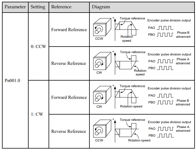
You can reverse the direction of Motor rotation by changing the setting of Pn001.0.
The default setting for Forward Rotation is counterclockwise (CCW) as viewed from the Drive end.
5.3 Overtravel Limit
5.3.1 Function Description
Overtravel is a safety function of the Drive that forces the Motor to stop in response to a signal input from a limit switch that is activated when a moving part of the machine exceeds the safe range of movement.
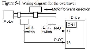
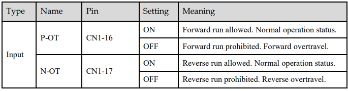
The overtravel signals include the P-OT (Forward Drive Prohibit) and the N-OT (Reverse Drive Prohibit)
signals.
You use the P-OT and N-OT signals to stop the machine by installing limit switches at the positions where you want to stop the machine that is operated by the Motor.
An example of wiring for the P-OT signal and the N-OT signal is shown in Figure 5-1.
Using the overtravel function is not necessary for rotating applications such as rotary tables and conveyors. No wiring for overtravel input signals is required.

5.3.2 Connecting the Overtravel Signal
To use the overtravel function, connect the following overtravel limit switch input signal terminals.
5.3.3 Enabling/Disabling the Overtravel Signal
Parameters can be set to disable the overtravel signal. If the parameters are set, there is no need to wire the overtravel input signal.
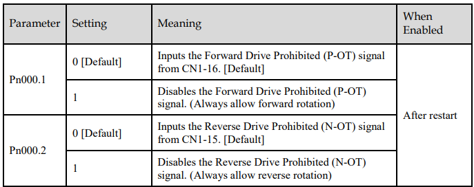
In addition, you can disable the overtravel limit function by not set the values 1 and 2 to parameter Pn509 (not allocate the P-OT signal and N-OT signal).
5.4 Motor Stopping Methods
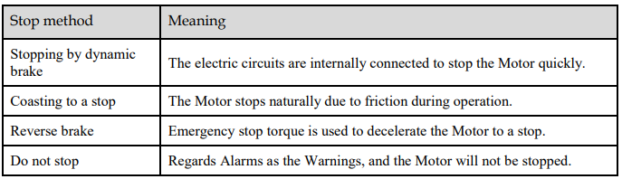
Following 4 ways are available to stop the drive alarming (Gr.1 or Gr.2), OT state, and servo OFF occurs:
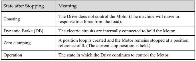
Also, you can let the Motor enter the following states after the Motor stops
5.4.1 Motor Stop Methods for Gr.1 Alarms, Safety State and Servo OFF
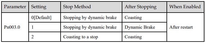
You can select the Motor stopping methods for Gr.1 Alarms occur, in Safe state or Servo OFF by setting the parameter Pn003.0.
5.4.2 Motor Stop Methods for Overtravel
You can select the Motor stopping methods for overtravel occurs by setting the parameter Pn003.1.
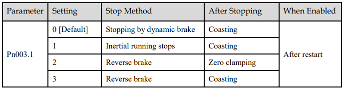
NOTE: The speed reference is set to 0 during the reverse brake, so that the soft stat function is unavailable. In addition, you shall set a reverse brake torque for stopping the Motor (Pn405).
5.4.3 Motor Stop Methods for Gr.2 Alarms
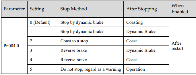
You can select the Motor stopping methods for Gr.2 Alarms occur by setting the parameter Pn004.0
5.4.4 Reverse Brake Torque Limit Setting
If Pn004.0 is set to 3 or 4, the Motor will be decelerated to a stop using the torque set in Pn405 as the maximum torque.

NOTE
This setting is a percentage of the rated torque.
The default setting is 300%. This setting is large enough to allow you to operate the Motor at the maximum torque. However, the maximum stop torque that you can actually use is the maximum torque of the Motor.
5.5 Holding Brake
5.5.1 Function Description
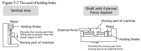
A holding brake is used to hold the position of the moving part of the machine when the Drive is turned OFF so that moving part does not move due to gravity or an external force.
You can use the brake that is built into a Motor with a Brake, or you can provide one on the machine.
The holding brake is used in the following cases.

5.5.2 Brake Operating Sequence
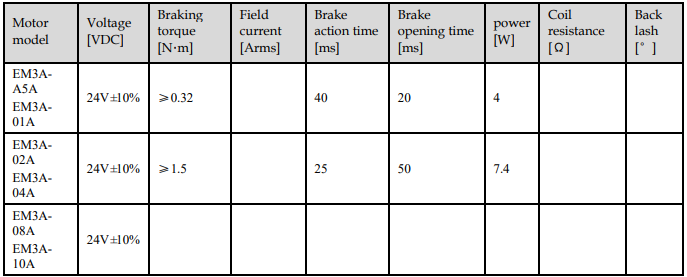
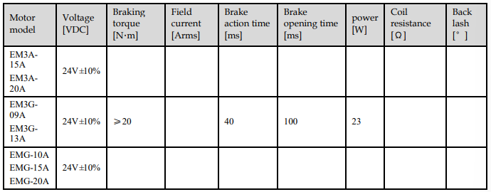
You must consider the time required to release the brake and the time required to brake to determine the brake operation timing, as described below.
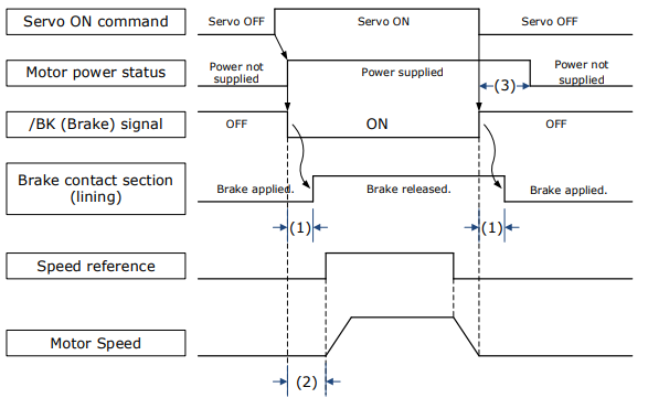
(1): The brake delay times for Motors with Holding Brakes.
(2): Before you output a reference from the host controller to the Drive, wait for at least 50 ms plus the time required to release the brake after you send the S-ON command.
(3): Use Pn506 (Servo OFF Waiting Time), Pn507 (Brake Enable Speed Threshold), and Pn508 (Brake Enable Waiting Time) to set the timing of when the brake will operate and when the servo will be turned OFF.
NOTE
Time Required to Release Brake: The time from when the /BK (Brake) signal is turned ON until the brake is actually released.
Time Required to Brake: The time from when the /BK (Brake) signal is turned OFF until the brake actually operates.
Table 5-1
5.5.3 /BK (Brake) Signal
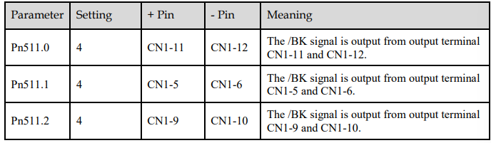
The /BK signal is turned OFF (to operate the brake) when the Servo is turned OFF or when an alarm is detected. You can adjust the timing of brake operation (i.e., the timing of turning OFF the /BK signal) with the Servo OFF Waiting time (Pn506).
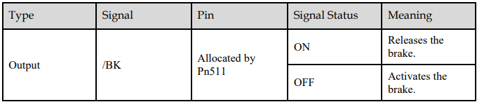
The /BK signal is not allocated in default setting, set its allocation in Pn511.
5.5.4 Output Timing of /BK Signal when Motor is Stopped
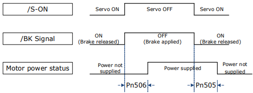
When the Motor is stopped, the /BK signal turns OFF as soon as the S-OFF (Servo OFF) command is received. Use the servo OFF delay time (Pn506) to change the timing to turn OFF power supply to the Motor after the S-OFF command is input.

NOTE
Set Pn505 as a positive value, when S-ON command is received, the /BK signal will be output first, and then power supplied to the Motor after waiting for this setting.
Set Pn505 as a negative value, when S-ON command is received, power supplied to the Motor immediately, and then output the /BK signal after waiting for this setting.
When the Motor is used to control a vertical axis, the machine moving part may move slightly due to gravity or an external force.
You can eliminate this slight motion by setting the servo OFF delay time (Pn506) so that power supply to the Motor is stopped after the brake is applied

5.5.5 Output Timing of /BK Signal when Motor is operating
If an alarm occurs or S-OFF command is received while the Motor is operating, the Motor will start stopping and the /BK signal will be turned OFF. You can adjust the timing of /BK signal output by setting the Brake Enable Waiting Time (Pn508).
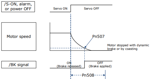
The /BK signal goes to H level (brake ON) when either of the following conditions is satisfied:
When the Motor speed falls below the level set in Pn507 after the power to the Motor is turned OFF.
When the time set in Pn508 is exceeded after the power to the Motor is turned OFF

5.6 Encoder Settings
5.6.1 Absolute Encoder Selection
Absolute encoders are fitted on motors with an encoder type of L; e.g. EM3A-02ALA211. These encoders require a battery supply to retain the absolute encoder data when the Drive power is removed.
With a system that uses an absolute encoder, the host controller can monitor the current position. Therefore, it is not necessary to perform an origin return operation when the power supply to the system is turned ON.
There are two types of encoders for the Motors. The usage of the encoder is specified in Pn002.2


5.6.2 Encoder Alarm Resetting
If alarm A.47 or A.48 occurs, replace the battery as soon as possible. After replacing the battery, perform the operation Absolute encoder alarm reset and Fn010 (Absolute encoder multi-turn reset.
For details about how to replace a battery and how to perform the replacement, see 3.5.4 Installing or
Replacing a Battery.
5.6.3 Multiturn Limit Setting
The multiturn limit is used in position control for a turntable or other rotating body. For example, consider a machine that moves the turntable shown in the following diagram in only one direction
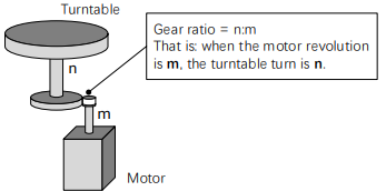
Because the turntable moves in only one direction, the upper limit to the number of revolutions that can be counted by an absolute encoder will eventually be exceeded.
The multiturn limit is used in cases like this to prevent fractions from being produced by the integral ratio of the number motor revolutions and the number of turntable revolutions.
For a machine with a gear ratio of n:m, as shown above, you can set Pn228 (OB 30A9h in EtherCAT) as m, and the value of m - 1 will be the setting for the multiturn limit setting.
The relationship between the number of turntable revolutions and the number of motor revolutions is
shown in the following figure.
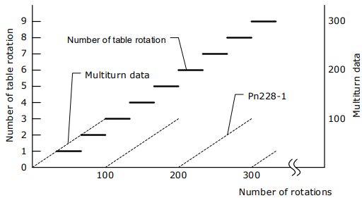

The data will change as shown below when this parameter is set to anything other than the default setting.
If the motor operates in the reverse direction when the multiturn data is 0, the multiturn data will change to the value set in (Pn228-1).
If the motor operates in the forward direction when the multiturn data is at the value set in (Pn228-1), the multiturn data will change to 0.
NOTE
The multiturn data will always be 0 in the following cases. It is not necessary to reset the absolute encoder in these cases.
When you use a single-turn absolute encoder
When you set Pn002.2 = 1 (Use the encoder as an incremental encoder)
5.6.4 Encoder pulse dividing output
Pulse dividing signals
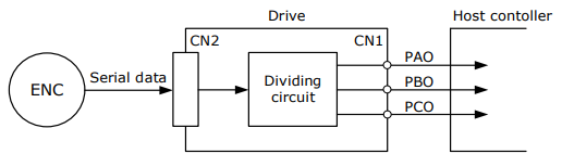
Encoder pulse dividing pulse output processes the signals sent from the encoder inside the driver, and outputs such signals to the outside in the form of two-phase pulses (Phase A, and Phase B) with 90° phase differential. It can be used as position feedback in the host controller.
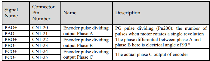
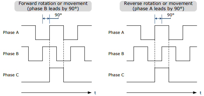
Note: Even in the reverse mode (Pn001.0=1), the pulse dividing output phase form is the same as the standard setting (Pn001.0=0).
Output Phase Form
Pulse Dividing Ratio Setting
Encoder pulse dividing means that the divider converts data into the pulse density (Pn200) set by the user parameter based on the pulse data of the motor encoder, and outputs it. The setting unit is number of pulses/revolution.

Set the number of pulses for PG output signals (PAO,/PAO,PBO,/PBO) externally from the servo drive through Pn200.
Feedback pulses from the encoder per revolution are divided inside the servo drive by the number set in Pn200 before being output.
Set the encoder pulse dividing ratio according to the system specifications of the machine or host controller.
The setting of the encoder pulse dividing number is restricted by the encoder's resolution.
[Output Example] Pn200=16 (when 16 pulses are output per revolution), the output examples of signals of encoder pulse dividing output phase A (PAO) signal and encoder pulse dividing output phase B (PBO) are shown below.

5.7 IO Signal Allocation
Functions are allocated to the pins on the I/O signal connector (CN1) in advance. You can change the allocations and the polarity for some of the connector pins. Function allocations and polarity settings are made with parameters.
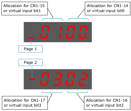
Operation panel can only display 5 digits. When distributing IO signals, it is necessary to display or set all the signals by page turning. The display instructions are detailed as follows (take Pn509 as an example).
5.7.1 Input Signal Allocations
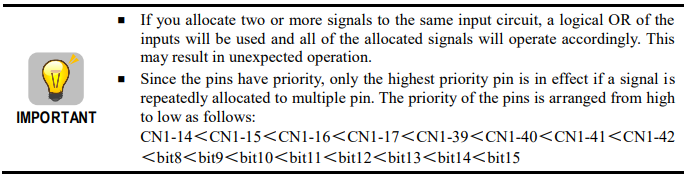
Allocation Description
CN1 provides a total of 8 pin numbers available for allocation of input signals, corresponding to the subparameters of Pn509 and Pn510. Moreover, there’re 8 virtual input bits controlled by Modbus communication, corresponding to the sub-parameters of Pn709 and Pn710.
Default Input Signals
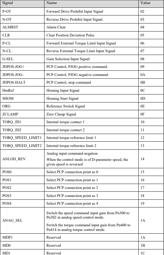
Table 5-2 lists the input signals that can be allocated and their corresponding values. Set the sub-parameters of Pn509, Pn510, Pn709 and Pn710 to use the following values, which means that they are allocated to the corresponding pins.
Table 5-2 Default Input signals

5.7.2 Output Signal Allocations
Allocation Description
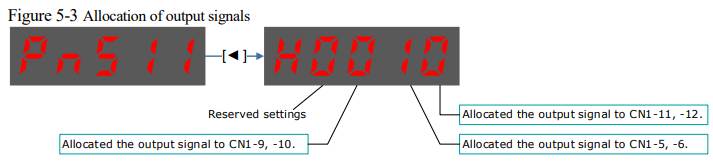
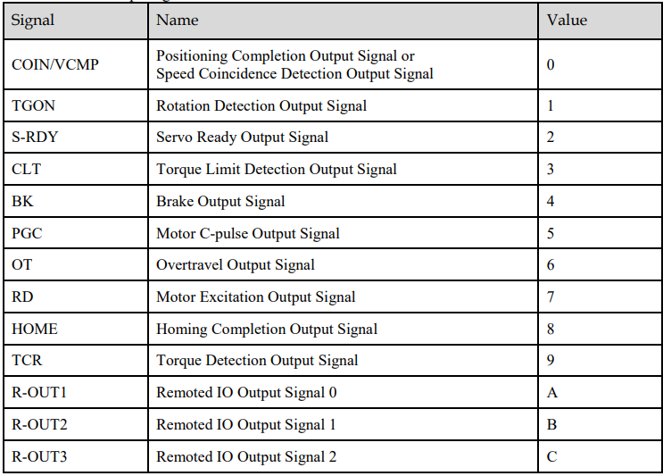
The I/O signal connector (CN1) on the Drive provides three group of pins (points) for allocating the output signals, corresponding to the parameter Pn511, as is shown in Figure 5-3.

Default Output Signals
Table 5-3 lists the output signals that can be allocated and their corresponding values. Set the parameter Pn511 to use the following values, which means that they are allocated to the corresponding pins.
Table 5-3 Default Output signals
5.8 Control Mode Selection
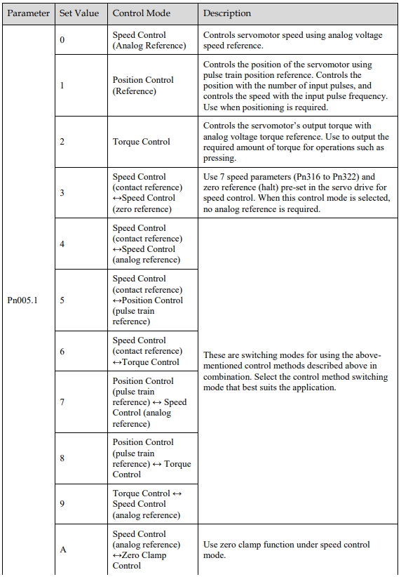
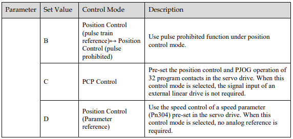
Speed control, position control and torque control are available to servo drive. Set through the control mode selection (Pn005.1).
5.9 Speed Control
Speed control is selected by Pn005.1:

5.9.1 Setting speed control
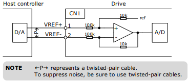
Speed reference input signal
To control the speed of the servo motor at a speed proportional to the input voltage, it is necessary to set the speed reference input signal.

[Note] Maximum input voltage: DC±10V
When performing position control by a host controller such as a programmable controller, connect it to the speed reference output terminal of the host controller.
Setting speed reference input gain
Sets the analog voltage level for the speed reference (V-REF) necessary to operate the servomotor at the rated speed through Pn300.

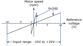
Speed Reference Input Example
Pn300=150 [factory setting]:
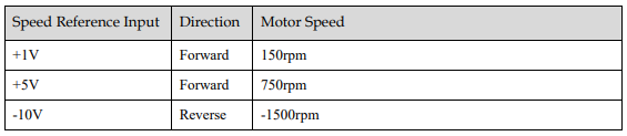
5.9.2 Adjustment of Speed Reference Offset:
When speed control is used, even if the command is 0V (the command speed is 0 or haled), the servo motor may rotate at a slight speed. This is because there is a slight deviation in the reference inside the servo unit. This slight deviation is called "offset". When the servo motor is moving at a slight speed, it is necessary to use the offset adjustment function to eliminate the offset.
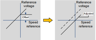
Auto Adjustment of Speed Reference Offset:
The auto adjustment of the Speed Reference Offset is a method for the servo drive to automatically adjust the voltage of the speed command after offset measurement.
NOTE
The measured offset will be saved in the servo drive.
The offset is not a parameter, so the offset will not be reset even if the parameter factory value (Fn001) is restored.
Following provides the steps for auto adjustment of the Speed Reference Offset.
Step 1 Confirm that the servo drive is in the servo OFF state.
Step 2 Input 0V command voltage from the host controller or external circuit.
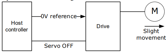
Step 3 Press [M] key several times to select the Utility Function Mode.

Step 4 Press [▲] key or [▼] key to select the function number Fn003.

Step 5 Press [◄] key and the operating panel is displayed as follows.

Step 6 Press [M] key to execute automatic offset adjustment.
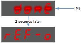
Step 7 Press the [◄] key to return to the display of the Fn003.
----End
Manual Adjustment of Speed Reference Offset
The manual adjustment of the speed reference offset is a method that inputs the speed command offset directly for adjustment. Use the manual adjustment in the following situations.
If a loop is formed with the host controller and the position error pulse is set to be zero when servolock is stopped.
To deliberately set the offset to some value.
To check the offset data set in the speed reference offset auto adjustment mode.
Following provides the steps for manual adjustment of the Speed Reference Offset.
Step 1 Input 0V command voltage from the host controller or external circuit.
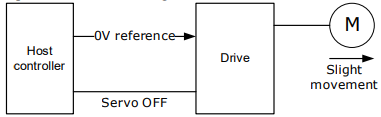
Step 2 Press [M] key on operating panel for several times to select the Utility Function Mode.

Step 3 Press [▲] key or [▼] key to select the function number Fn004.

Step 4 Press [◄] key and the operating panel is displayed as follows.

Step 5 Turn ON the servo S-ON signal, so that the servo drive enters the servo ON state.
Step 6 Press the [M] key for one second to display the current speed reference offset.

Step 7 Press [▲] key or [▼] key to adjust the offset manually.
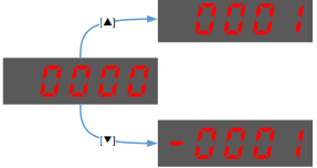
[Note] The adjustment range of the offset is -1024 to 1024.
Step 8 Press and hold the [◄] key for 1 second to return to the manual adjustment display.

Step 9 Press the [M] key to return to the display of the Fn004.
----End
5.9.3 Soft Start
The soft start function converts the stepwise speed reference inside the drive to a consistent rate of acceleration and deceleration.
First, the user needs to select the running curve of the speed reference via Pn310 (speed reference curve form)
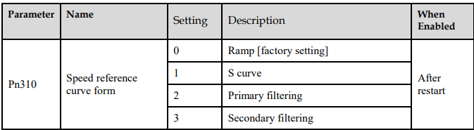
Use this function when you want to achieve smooth speed control (including internally set speed control).
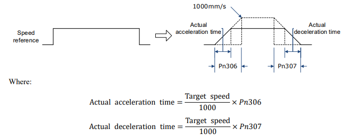
When speed reference uses ramp form (Pn310=0)
The figure below shows the timing diagram of the speed reference in the ramp form (Pn310=0). Among them, Pn306 is the time interval for the motor to accelerate from the stop state to speed of 1000rpm, and Pn307 is the time interval for the motor from 1000rpm to the stop state.

When speed reference uses S-curve (Pn310=1)
The figure below shows the timing diagram of the speed reference in the S-curve (Pn310=1). Among
them, Pn309 is the time interval for the motor to accelerate from the stop state to the target speed, or the
time interval for the motor to decelerate from the target speed to the stop state.

Moreover, transition form of the S-curve via Pn311 can also be selected. User can try and choose the appropriate setting.

When speed reference uses filtering (Pn310=2 or 3)
Pn308 (speed filter time constant) smooths the speed reference by applying a 1st-order delay filter can be applied to the analog speed reference (VREF) input.
This parameter is generally not set. If the set value is too large, the responsiveness may be reduced. It is recommended to set while confirming the responsiveness.

5.9.4 Zero Clamp Function
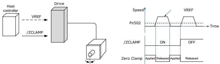
When the zero clamp function is used for speed control, the upper controller is a system that forms a loop.
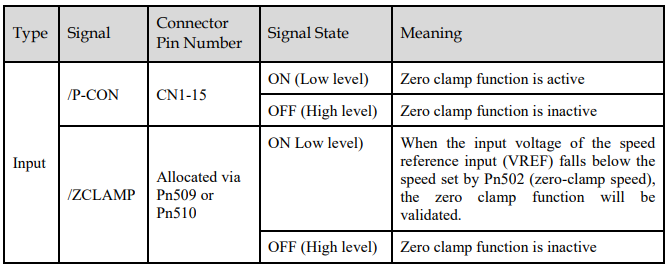
The zero clamp function locks the servo when the input voltage of the speed reference (VREF) drops below the set speed in the zero clamp level parameter (Pn502) while the zero clamp signal (/ZCLAMP) is ON (low level). By this moment, a loop is formed inside the servo drive, ignoring the speed reference.

The servo motor is fixed within ±1 pulse of the zero clamp effective position. Even if it moves due to external force, it returns to the zero-clamp position
Adjust the position loop gain in Pn104 (position loop gain) if the servomotor oscillates in the zero clamp state. If the gain switching function is used, adjusting Pn109 (2nd position loop gain) is also required.
Zero-Clamp Signal Allocations
The /ZCLAMP signal is not allocated in the factory setting, and the user needs to set it through Pn509 or Pn510.
Setting Zero Clamp Function
When the control mode (Pn005.1) is set to A, the zero clamp function is active when the following two conditions are satisfied
Low level when /P-CON is ON
The speed reference (VREF) drops below the set value of Pn502
5.9.5 Speed Coincidence Detection (/VCMP) Signal
The Speed Coincidence Detection (/VCMP) Signal is the signal output when the speed of the servomotor coincides with the reference speed. It is used in occasions such as interlocking with the upper controller.
This output signal can only be used during speed control.
 [Note] In position control, CN1-11, 12 output /COIN (positioning completion) signal.
This output signal can be distributed to other output terminals via Pn511. For details, please refer to "5.7.2 Output Signal Allocation".

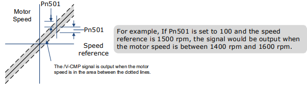
The VCMP signal is output when the difference between the motor speed and the reference speed drops below the set speed of Pn501.
5.10 Position Control
Use Pn005.1 to select Position Control:

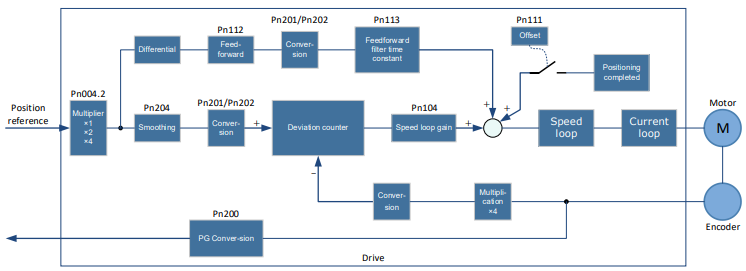
The control block diagram for position control is shown in figure below.
5.10.1 Basic Settings of Position Control
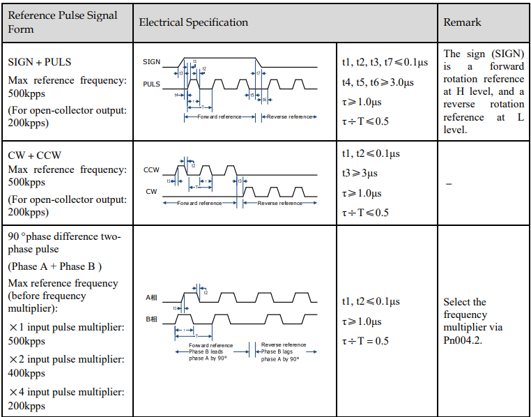
Setting position reference input form
Use Pn004.2 to set the input form of the position reference.
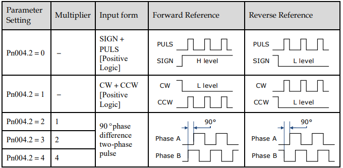
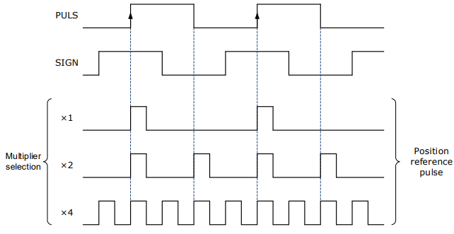
The input multiplier can be set when the 90º phase difference is of two-phase pulse reference form.
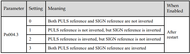
Also, the user can choose whether to invert the PULS signal and SIGN signal using Pn004.3.
Electrical specifications for position reference input
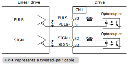
Connection Example
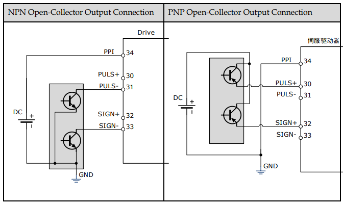
The pulse train output form of the reference controller includes the followings.
Linear drive
+24V open-collector output
+12V/+5V open-collector output
[Connection Example for Linear drive Output]
Applicable linear driver: SN75174 manufactured by TI or MC3487 or the equivalent.
[Connection Example for Open-Collector Output]
5.10.2 Function and Setting of Position Error Clear (/CLR) Signal
Allocation of Position Error Clear Signal

When the /CLR signal is set to low level, clear error counter:
The error counter inside the servo drive is set to“0”
Position loop operation is disabled.
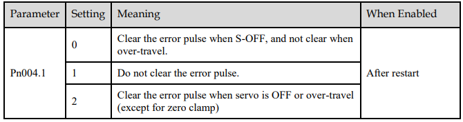
Setting the Clear Signal Mode
In position control mode, pulses will be still presented in the servo drive when servo OFF, thus it should be cleared when servo drive is turned ON (S-ON). Setting Pn004 to choose whether clearing the pulses automatically when servo OFF.
5.10.3 Electronic Gear
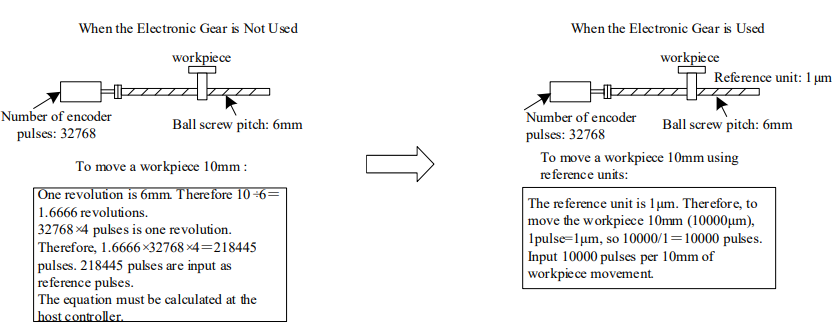
Function Overview
The electronic gear enables the workpiece travel distance per input reference pulse from the reference controller to be set to any value.
One reference pulse from the reference controller, i.e., the minimum position data unit, is called “1 reference unit”.
If the mechanical reduction ratio between the motor shaft and the load side is set to m/n, the setting value of the electronic gear ratio can be calculated according to following formula. (When the servomotor rotates m revolutions, the load shaft rotates n revolutions)

NOTE
Range of electronic gear ratio: 0.01≤electronic gear ratio (B/A)≤100
If the electronic gear ratio is outside this range, the servo drive will not operate properly. In this case, modify the load configuration or reference unit.
Divide the numerator and denominator into integers within the setting range when it exceeds the setting rang.
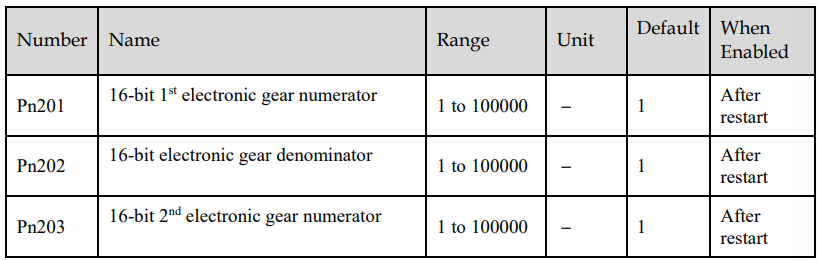
2nd Electronic Gear Switching
Switch between electronic gear ratio numerator 1 (Pn201) and electronic gear ratio numerator 2 (Pn203) according to the external/P-CON signal. The switching sequence is determined by the setting of Pn002.0.
This function is enabled by user parameter Pn001.3.

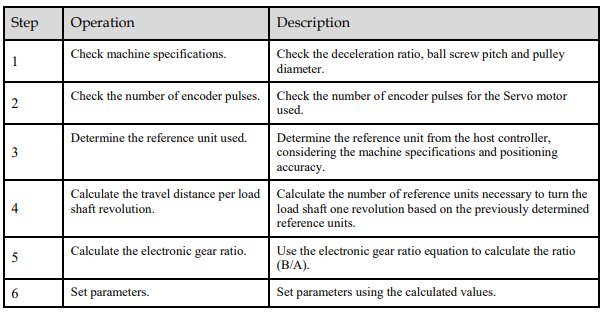
Setting Steps
Set the electronic gear ratio as per the steps and instructions described in the table below.
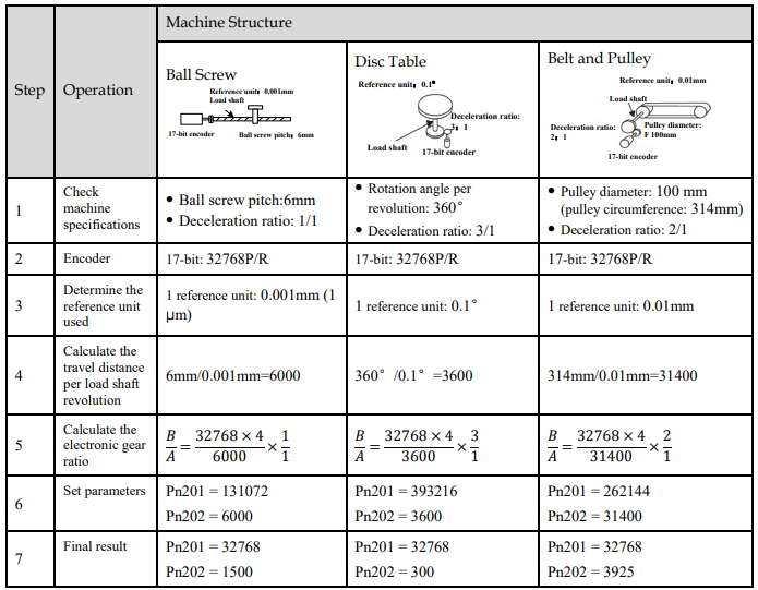
Setting Examples
NOTE
Reduce the fraction (both numerator and denominator) if the calculated result will not be within the setting range. For example, reduce the above numerators and denominators by four or other numbers to obtain the final results in step 7 and complete the settings.
Electronic Gear Ratio Equation
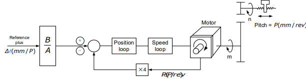
Where: Δl is the reference unit; P_G is the encoder pulse; P is the pitch of the ball screw; m/n is the
reduction ratio.

Set A and B with the following parameters Pn202 and Pn201
5.10.4 Smoothing
The smoothing filters the reference pulse input to make the travel of the servomotor smoother. This function is more effective in the following cases.
When the host controller that outputs a reference that cannot perform acceleration/deceleration processing.
When the reference pulse frequency is too low.
When the conversion of position reference is large (𝑃𝑛201 𝑃𝑛202 ≥ 10)
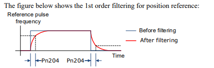
[Note] This setting has no effect on the travel distance (reference pulse number). Set the position reference filtering method using Pn205 (position reference filter form selection).
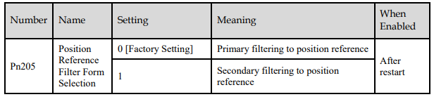
Then set the filter time of the position reference using Pn204 (position reference filter time constant).


5.10.5 Positioning Completion (/COIN) Signal
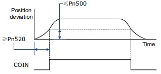
This signal indicates that servomotor movement has been completed during position control. Use the signal to confirm that positioning has been completed at the host controller.

[Note] CN1-11, 12 output the VCMP (speed coincidence) signals during speed control.
This output signal can be allocated to an output terminal with parameter Pn511. Refer to "0 Output Signal Allocation".
The positioning completion (COIN) signal is output when the difference (position error pulse) between the number of reference pulses output by the host controller and the travel distance of the servomotor is less than the value set in tPn500, and the stabilization time is more than the value of Pn520 (position completion time).

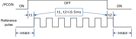
5.10.6 Reference Pulse Inhibit Function (INHIBIT)
This function stops (inhibits) the servodrive from counting input pulses during position control. When this function is active, the servodrive enters a state where it cannot receive reference pulse input.
When this function is used, it is necessary to set Pn005.1=B.

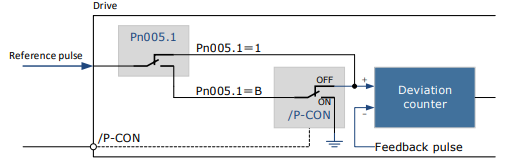
Inhibit (INHIBIT) is switched via/P-CON signal

5.11 Torque Control
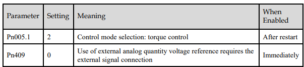
This mode inputs a torque reference in the form of an analog voltage reference to the servodrive, and controls the operation of the servomotor using a torque proportional to the input voltage. This control mode needs to be selected via Pn005.1 and Pn409.
5.11.1 Basic Settings of Torque Control
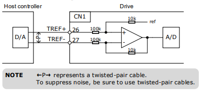
Specification of Torque Reference Signal Input
To apply torque control to the servomotor with a torque proportional to the input voltage, it is necessary to set the torque reference input signal.

[Note] Max input voltage: DC±10V.
When performing position control by a host controller such as a programmable controller, connect it to the analog reference output terminal of the host controller.
Setting Torque Reference Input Gain
Pn400 is used to set the analog voltage value of the torque reference (TREF) that operates the servomotor at the rated speed.

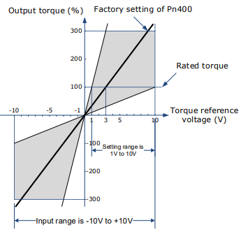
Torque Reference Input Example
When Pn400=30:
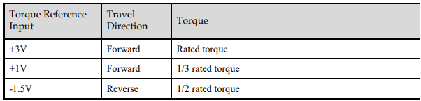
5.11.2 Adjustment of Torque Reference Offset
When using torque control, the servomotor may rotate slowly even when 0V (reference speed is 0 or stop) is specified as the analog reference voltage. This occurs when there’s slight offset for internal reference of servo drive. Such slight offset is called “Offset”. When the servo motor is moving at a low speed, it is necessary to use the offset adjustment function to eliminate the offset.
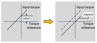
Auto Adjustment of the Torque Reference Offset
The auto adjustment of torque reference offset automatically measures the offset and adjusts the torque reference voltage automatically
NOTE
The measured offset will be saved in the servo drive.
The offset is not a parameter, so it will not be reset even if the parameter factory value (Fn001) is restored.
The following provides the operating steps for auto adjustment of the torque reference offset.
Step 1 Make sure that the servo drive is in the servo OFF state.
Step 2 Input the 0V reference voltage from the host controller or external circuit.
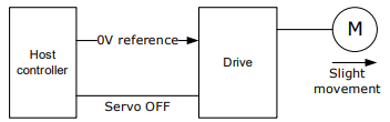
Step 3 Press the [M] key to select the utility function mode.

Step 4 Press the [▲] or [▼] key to select the utility function number Fn003.

Step 5 Press [◄] key and the operating panel is displayed as follows.

Step 6 Press the [M] key, and the reference offset will be automatically adjusted.
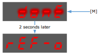
Step 7 Press the [◄] key to return to the utility function mode display Fn003.
----End
Manual Adjustment of the Torque Reference Offset
The manual adjustment of torque reference offset directly inputs the torque reference offset for adjustment. Manual adjustment is used in the following cases.
If a position loop is formed with the host controller and the error is zeroed when servolock is stopped.
To deliberately set the offset to some value.
Use this mode to check the offset data that was set in the auto adjustment mode of the torque reference offset.
The following provides the operating steps for manual adjustment of the torque reference offset.
Step 1 Input the 0V reference voltage from the host controller or external circuit.
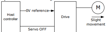
Step 2 Press the [M] key on the operating panel to select the utility function mode.

Step 3 Press the [▲] or [▼] key to select the utility function number Fn004.

Step 4 Press [◄] key and the operating panel is displayed as follows.

Step 5 Turn on the S-ON signal to make the servo drive enter the servo ON state.
Step 6 Press and hold the [M] key for 1 sec or longer, the operation panel will display the current torque reference offset.

Step 7 Press the [▲] or [▼] key to adjust the offset manually.
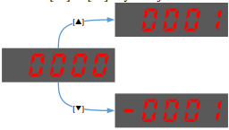
[Note] The adjustment range of the offset is -1024 to 1024.
Step 8 Press and hold the [◄] for 1 sec, and return to the display of manual adjustment.

Step 9 Press the [◄] key to return to the function number display Fn004.
----End
5.11.3 Setting Torque Reference Input Filter
It is possible to apply a 1st -order delay filter to the analog torque reference (VREF) input via Pn105 (torque reference filter time constant), to smooth the torque reference.
This parameter is generally not set. If the set value is too large, the responsiveness may be reduced. It is recommended to set while confirming the responsiveness.
