6. CANopen Communication
6.1 Wiring and Connection
Connection diagram
Terminal arrangement
Signal Definition
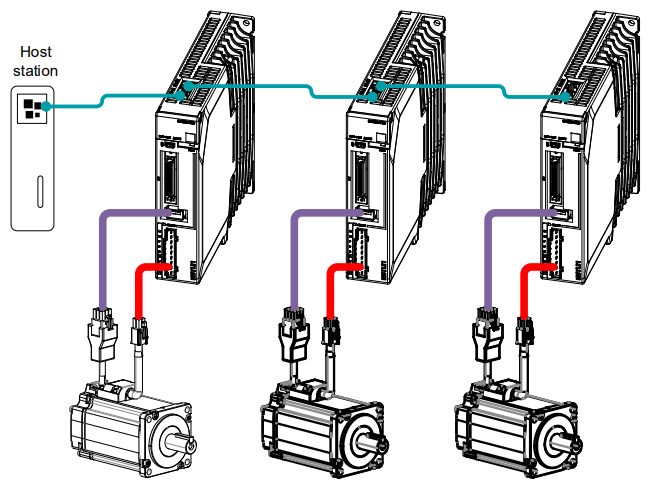
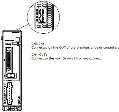
The external communication connection terminals (CN3-IN and CN4-OUT) are of RJ45 connectors. The interface line as the master or controller is connected from CN3-IN, and CN4-OUT is connected to the CN3-IN terminal of next drive (slave).
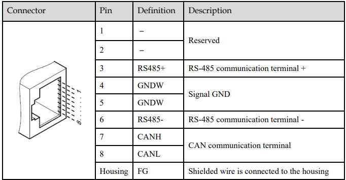
[Note] The signal definitions of CN3-IN and CN4-OUT are the same.
Wiring Instructions
When wiring the CANopen communication, following precarious shall be taken.
Do not short connect pin 1 and pin 2.
Use UTPs (at least 2 pairs) with shielding layer. One pair of UTPs is connected to CANL and CANH; the other is connected to ISO_GND.
The shielding layer is generally grounded reliably at a single point.
To prevent signal reflection, it is recommended to connect two 120Ω (1%, 1/4W) terminal matched resistors at both ends of the bus.
It is recommended that the CAN bus networking node is ≤16.
The wiring diagram is shown below.

6.2 CANopen Overview
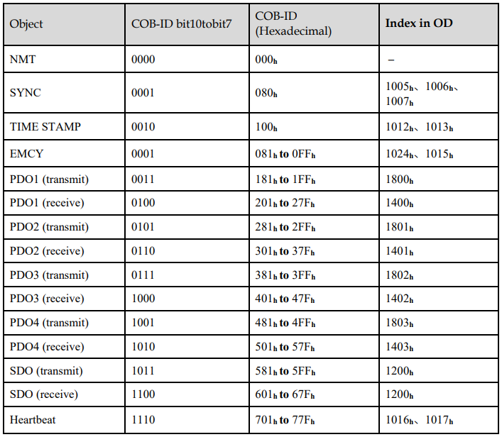
6.2.1 CAN Identifier List
6.2.2 Service Data Objects (SDO)
SDO is used to visit the object dictionary of a device. Visitor is called client. The CANopen device whose object dictionary is visited and required to supply the asked service is called server. CANopen messages from a client and servo all contain 8 bits (not all of them are meaningful). A request from a client must be confirmed by a server.
There are 2 method of transferring SDO:
Expedited transfer: contains 4 bytes at maximum
Segmented transfer: contains more than 4 bytes
Basic structure of SDO:

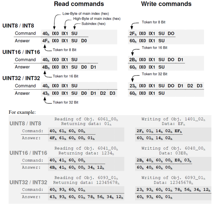
SDO read/write structure:
SDO message format for parameter read/write operation:
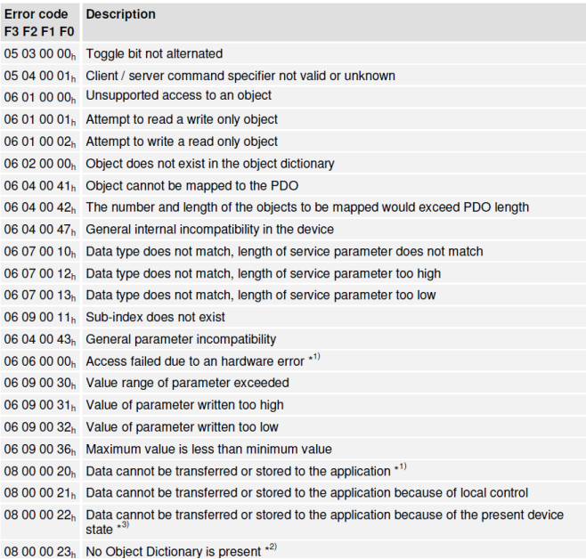
Format of SDO read/write error message:

Error code is defined as follows:
6.2.3 Process Data Objects (PDO)
PDO is applied to transferring real time data which will be conveyed from a producer to one or multiple clients. Data transferring will be limited to 1 to 8 bytes. There is no hand-shake restriction in PDO communication, which means data has been redefined, so clients could process the received data for vary short time. PDO content will be only defined by its CAN ID, assuming producers and clients know PDO content from its CAN ID.
2 objects in object dictionary are used for each PDO.
PDO communication parameter: It contains COB-ID, transferring type, restriction time and cycle of timer used by PDO.
PDO mapping parameter: It contains a list of objects in the object dictionary. These objects are mapped into PDO, includes their data length in bits. Producers and clients must know this mapping to explain the content of PDO.
The content of PDO’s message is predefined or configured when the network initializes. Mapping application object into PDO is described in object dictionary. If a device (producer and client) support dynamic mapping, SDO could be used to configure PDO’s mapping parameter. Our servo drive supports dynamic PDO mapping. There are 2 rules for PDO mapping to follow:
Each PDO could be mapped into 4 objects.
The length of each PDO will be no more than 64 bits.
PDO mapping process
1. Set the sub-index of PDO coordinated mapping parameter (e.g. 1600 h or 1A00 h) as o
2. Revise the sub-index from 1 to 4 of PDO coordinated mapping parameter (e.g. 1600 h or 1A00 h).
3. Set the sub-index 0 of PDO coordinated mapping parameter (e.g. 1600 h or 1A00 h) as legal Number (number of PDO’s mapping objects)
4. PDO mapping completed.
Ways to transmit PDO
Synchronous (synchronization by receiving SYNC object)
Cycle: Transmission triggered after every 1 to 240 SYNC messages.
Asynchronous
Transmission triggered by special object event regulated in sub-object protocol.
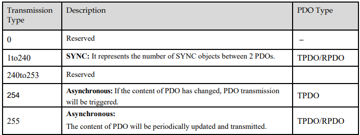
Definition of transmission type of PDO
One PDO could set a frozen time which is the shortest interval time between 2 continuous PDO. It could prevent the bus from being occupied by amount of data with high priority. Frozen time is defined by 16 bit unsigned integer number and its unit is 100us
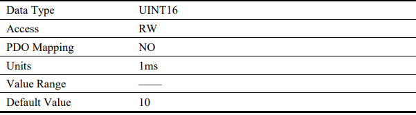
One PDO could set a timing period. When the regulated time is violated, a PDO transmit could be triggered without a trigger bit. Object timing period is defined as 16 bit unsigned integer and its unit is 1ms
PDO mapping example
Map the 3 objects to PDO1 (transmit). PDO1 (transmit) is required to be asynchronous periodic type with period time as much as 10ms and frozen time as much as 2ms.
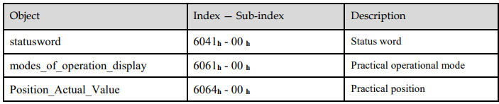
1. Clear number_of_mapped_objects
number_of_mapped_objects(1A00 h: 00 h)= 0
2. Set the parameter for mapping objects
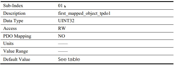
Index =6041 h Subin. = 00h Length = 10 h ⇒ 1st_mapped_object(1A00 h: 01 h)= 60410010 h
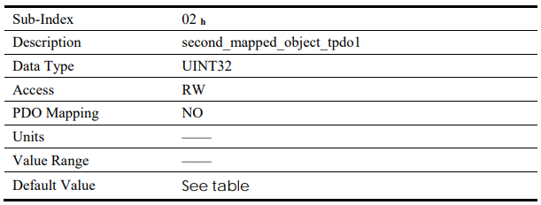
Index =6061 h Subin. = 00h Length = 08 h ⇒ 2st_mapped_object(1A00 h: 02 h)= 60610008 h
Index =60FD h Subin. = 00h Length = 20 h ⇒ 3st_mapped_object(1A00 h: 03 h) = 60FD0020 h
3. Set number_of_mapped_objects
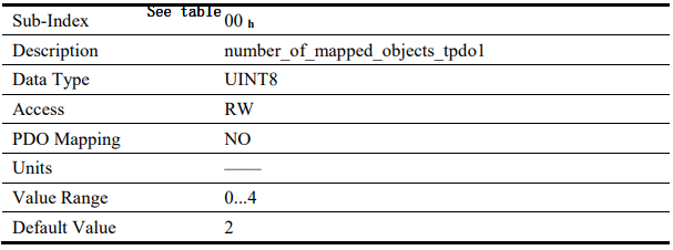
number_of_mapped_objects(1A00 h: 00 h)= 3
4. Set PDO communication parameter
PDO1 (transmit) is asynchronous periodical type ⇒ transmit_type (1800 h: 02 h)= FF h
Frozen time 2ms(20×100us) ⇒ inhibit_time (1800 h: 03 h)= 14 h
Period time 10ms(10×1ms) ⇒ event_time (1800 h: 05 h)= 0A h
5. PDO mapping completed.
PDO Parameters
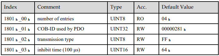
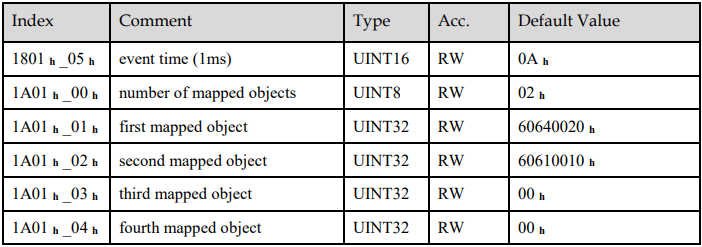
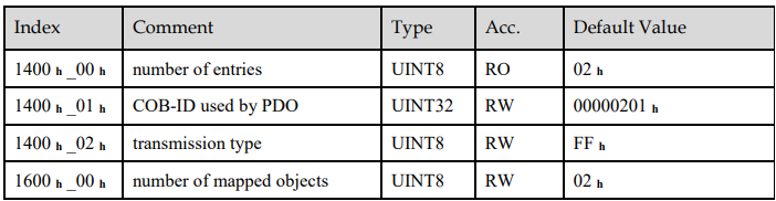
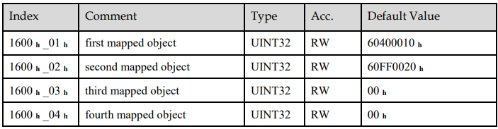
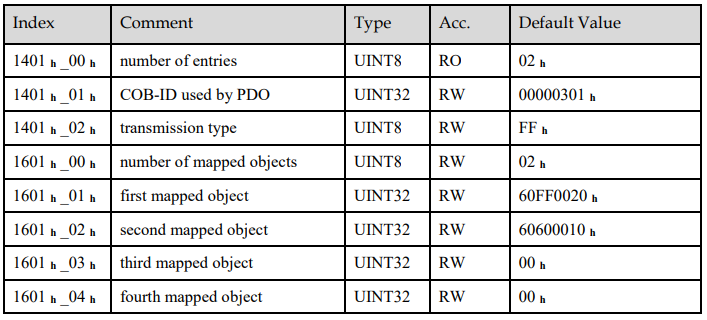
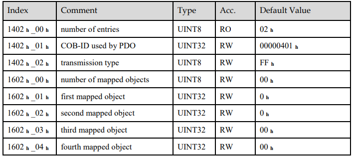
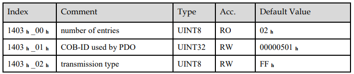
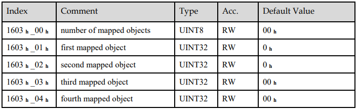
Drive contains 4 transmit PDOs and 4 receive PDOs. The detailed communication parameter and mapping parameter of the first transmit/receive PDO is as below and those of the rest 3 transmit/receive PDO are the same as the first PDO.

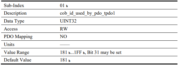
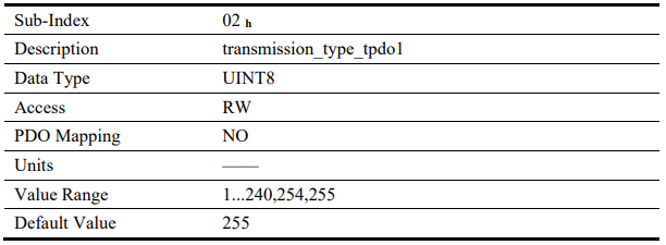
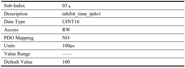



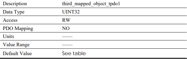
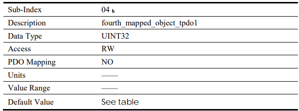
T-PDO1

T-PDO2
T-PDO3
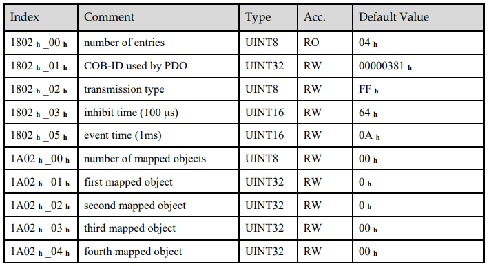
T-PDO4
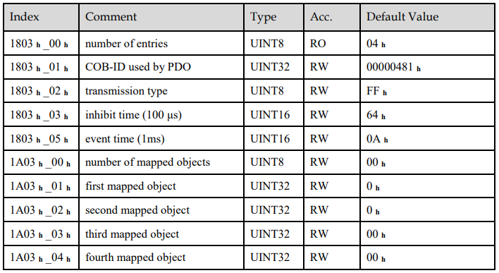
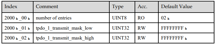
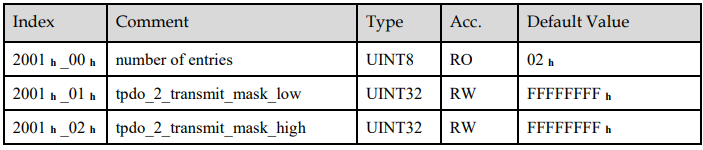
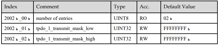
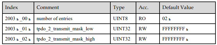
If transmit type is 254 (if PDO content has changed, such PDO is triggered to send), use of the following object can shield parts of PDO changers. Only when the un-shield bit has changed, PDO occurs. If wants shielding any bit, the corresponding bit of object write to 0.
tpdo_1_transmit_mask
tpdo_2_transmit_mask
tpdo_3_transmit_mask
tpdo_4_transmit_mask
R-PDO1
R-PDO2
R-PDO3
R-PDO4
6.2.4 SYNC Message
Synchronization object is used for controlling data synchronize transmit. For example, starting synchronously several axes. The transmission of synchronous message is based on Producer-Customer model. All the nodes of synchronous PDO can receive (at the same time) the message as customer and synchronize other node.
The general mode is that the SYNC master node sends the SYNC object regularly, and the SYNC slave node executes the task synchronously upon receiving it.
CANopen suggests a COB-ID with highest priority to ensure that synchronized signal could be transmitted properly. Without transferring data, SYNC message could be as short as possible.
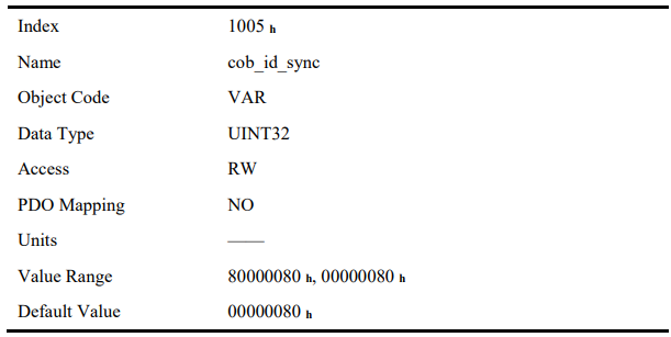
The COB-ID of the SYNC message is fixed at 080h, and the COB-ID can be read from 1005 h in the object dictionary
6.2.5 Emergency Message
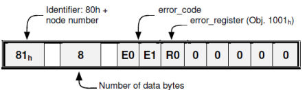
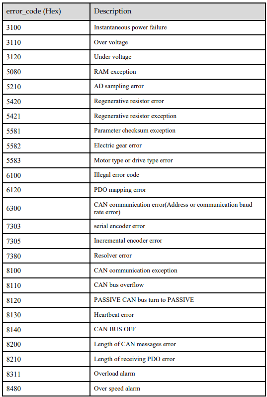
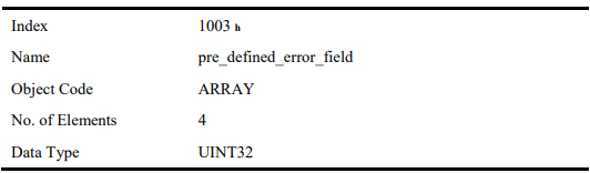
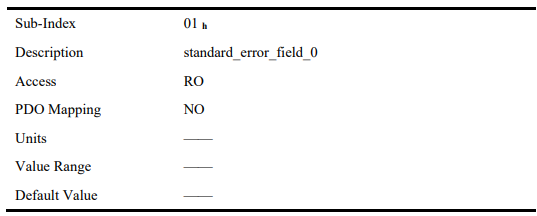
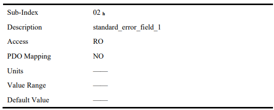
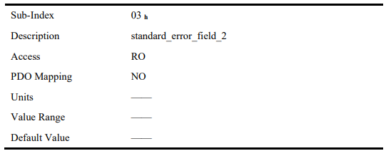
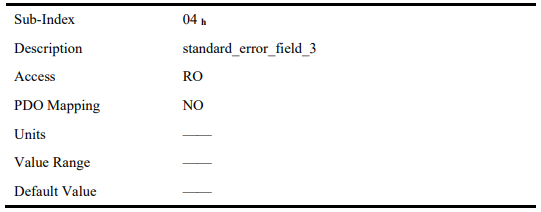
When an alarm occurs to drive, CANopen will initiate an Emergency message to inform the current drive type and error code to clients. Error code displayed on panel can be read on low byte of 603Fh object.
Structure of Emergency Message:

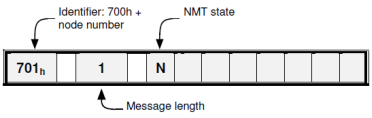
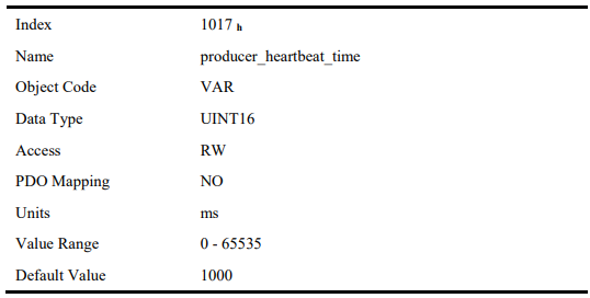
6.2.6 HEARTBEAT Message
Structure of Heartbeat Message
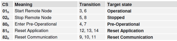
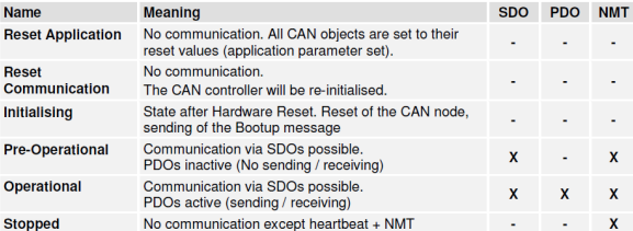
6.2.7 Network management (NMT service)
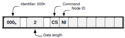
Structure of Message
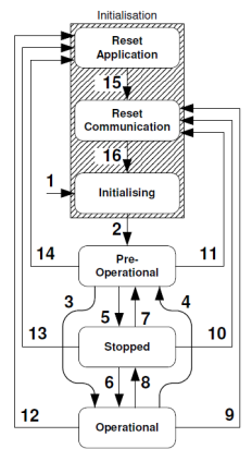
NMT state transition diagram
6.3 Unit Conversion
Default user unit of the drive:
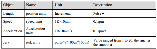
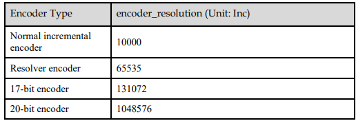
﹡ Ordinary incremental encoder outputs 10,000 pulses per revolution;
Rotary encoder outputs 65,536 pulses per revolution;
17-bit encoder outputs 131,072 pulses per revolution;
20-bit encoder outputs 1,048,576 pulses per revolution;
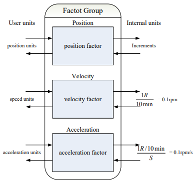
6.3.1 Parameters for Unit Conversion
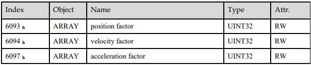
6.3.2 Position factor
Position factor module converts all the measuring units of client into internal unit of servo drive (pulse) and at the same time converts the unit (pulse) of all the output from the drive into the measuring unit of clients (position units). Position factors includes numerator and division.
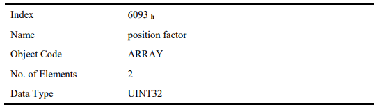
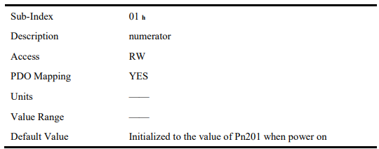
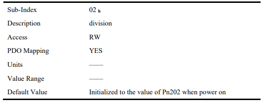
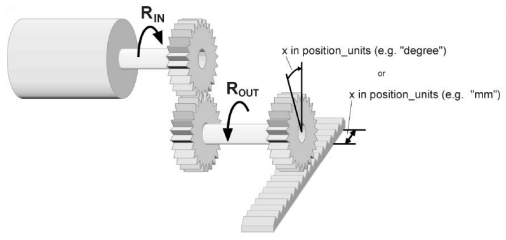
For calculating the position factors easily, 2 parameters as below are defined:
gear_ratio: Reduction ration between the load shaft and the motor shaft. (When motor’s revolution is n and load’s revolution is m, then gear_ratio = m/n)
feed_constant: the distance of position units’ movement when load shaft rotates for one revolution. position factor is calculated according to:

6.3.3 Velocity factor
Velocity factor module converts all the speed measuring unit at customer side into drive’s internal measuring unit as much as 0.1rpm. And at the same time, it converts the drive’s output velocity unit (0.1rpm) into user’s velocity units. Velocity factor parameters includes a numerator and a division.
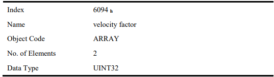
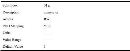
For calculating velocity factor easily, 3 parameters are defined as below:
time_factor_v: drive’s internal time unit and user’s time unit. (For example: 1min = 1/10 10min)
gear_ratio: the reduction ration between the load shaft and the motor shaft. (When motor’s revolution is n and load’s revolution is m, then gear_ratio = n/m)
feed_constant: the distance of position units’ movement when load shaft rotates for one revolution. velocity factor is calculated according to:

6.3.4 Acceleration factor
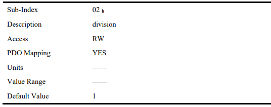
Acceleration factor module converts all the acceleration units at the perspective of clients into drive’s internal unit (0.1rpm) and at the same time converts the output acceleration units (0.1rpm) from the drive into acceleration units at the perspective of clients. Acceleration factor parameters contain numerator and division.
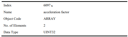
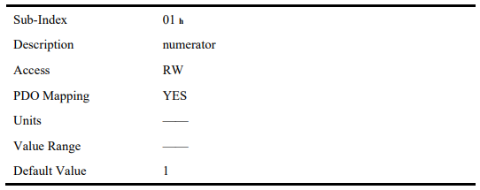
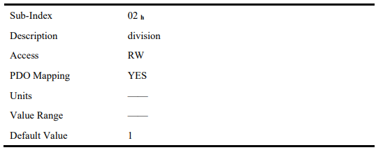
For calculating velocity factor easily, we could define 3 variables as below:
time_factor_a: The ratio between drive’s internal time square and clients’ time square. (For example: 1min2 = 1min*min = 60s*1min =60/10 10min/s)
gear_ratio: the reduction ration between the load shaft and the motor shaft. (When motor’s revolution is n and load’s revolution is m, then gear_ratio = n/m)
feed_constant: the distance of position units’ movement when load shaft rotates for one revolution. acceleration factor is calculated according to:

6.4 Position Control Function
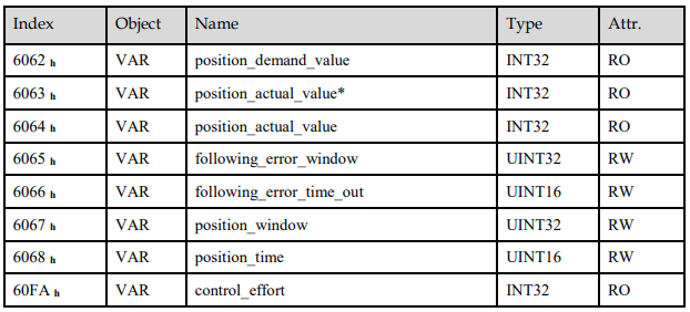
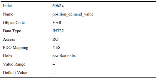
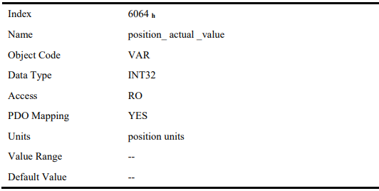
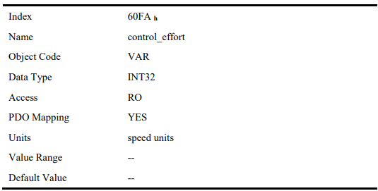
The demanding position (position_demand_value) output from Trajectory unit is the input of drive’s position loop. Besides, the actual position( position_actual_value) is measured through the motor’s encoder. Position control is influenced by parameter settings. To ensure the stability of the control system, we have to limit the output of postion loop (control_effect). This output becomes the given speed for speed loop. In the Factor group, all the input and output are transformed into the internal measuring unit of the servo drive.
Following Error
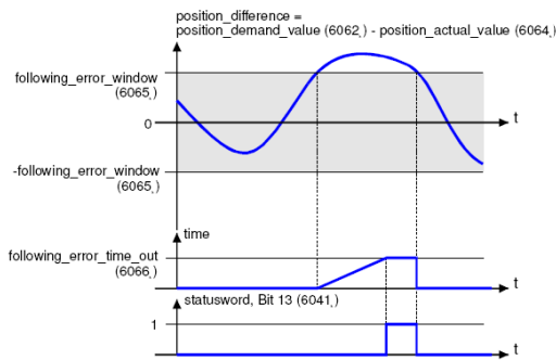
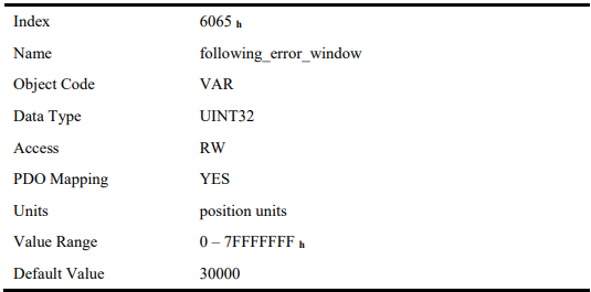
The deviation of the actual position value (position_actual_value) from the desired position value (position_demand_value) is named following error. As shown in figure above, if for a certain period of time this following error is bigger than specified in the following error window (following_error_window) bit 13 (following_error) of the object statusword will be set to 1.
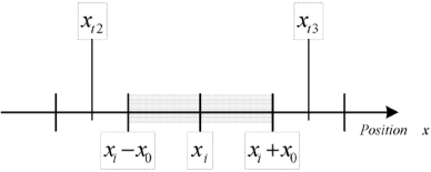
Figure above shows how the window function is defined for the message "following error". The range between xi-x0 and xi+x0 is defined symmetrically around the desired position (position_demand_value) xi.
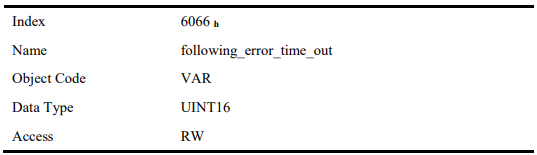
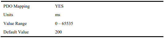
For example the positions xt2 and xt3 are outside this window (following_error_window). If the drive leaves this window and does not return to the window within the time defined in the object
following_error_time_out then bit 13 (following_error) in the statusword will be set to 1.
Position Reached
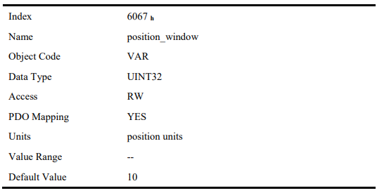
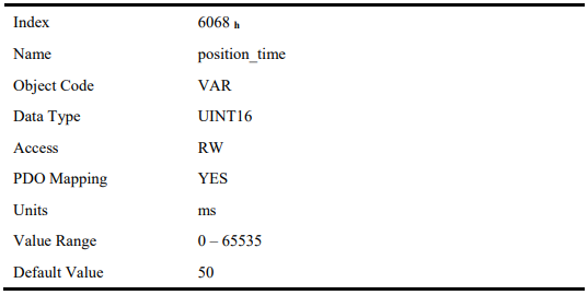
This function offers the chance to define a position window around the target position (target_position). If the actual position of the drive is within this range for a certain period of time – the position_window_time – bit 10 (target_reached) will be set to 1 in the statusword. As shown in figure below.
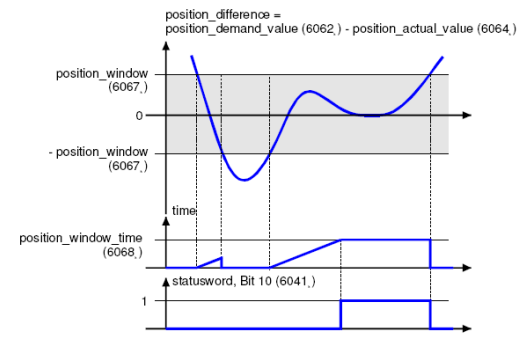
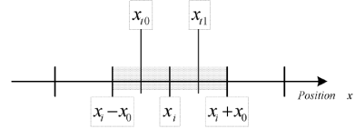
The figure below shows the position_windows are symmetrically distributed around the target_position), i.e. the range from xi-x0 to xi + x0. For example, the positionsxt0 and xt1 are in the position windows. If the drive is in the window, a fixed period starts timing. If the fixed period reaches the position_ window_ time and the drive position is always in the window during the time, then bit10 (target_reached) in the statusword_will be set to 1. As soon as the drive position leaves the window, bit10 (target_reached) in the statusword will be cleared to zero immediately.
6.5 Device Control
6.5.1 Control State Machine
The master controls the drive through the controlword, and knows the current status of the drive by reading the statusword of the drive.
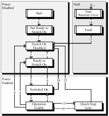
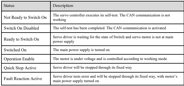
According to figure above, the state diagram can be divided into three main parts: "Power Disabled" (means the main power supply is switched off), "Power Enabled" (the main power supply is turned on) and “Fault”. All states enter "Fault" after an alarm occurs. After switching on the servo controller initializes itself and enters the state SWITCH_ON_DISABLED. In this state CAN communication is possible and the servo controller can be parameterized (e.g. the working mode of drive can be set to "PP" mode). The main power supply remains switched off and the motor is not excited. Through the state transitions 2, 3 and 4, the state OPERATION_ENABLE will be reached. In this state the main power supply is turned on and the servo controller controls the motor according to the parameterized working mode. Therefore, it must be confirmed that the parameters of the drive have been correctly configured and the corresponding input value is zero before such state. The circuit main power supply will be turned off after state transition 9 is done. Once the driver alarms, the driver enters FAULT.

6.5.3 Controlword
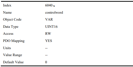

Bit0to3 and Bit7
The transmission of the state machine is triggered by the control command composed of those 5 bits.
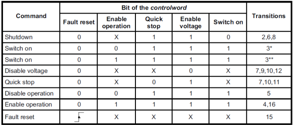
[Note] X means this bit could be ignored.
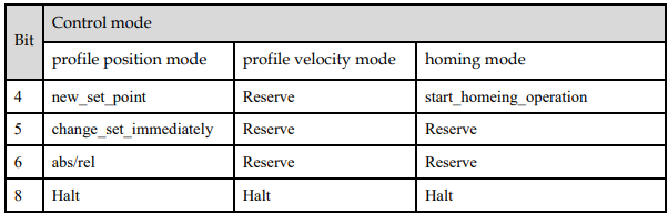
Bit4, 5, 6 and 8
The definition of this 4 bit is different in different control mode
Other bits
All reserved.
6.5.4 Statusword
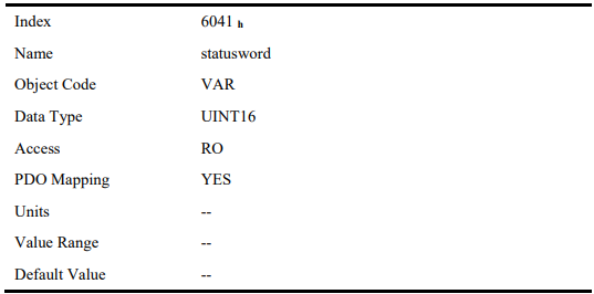
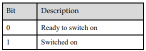
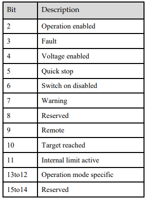
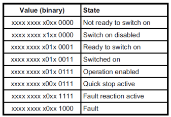
Explanation of statusword bit is as below:
Bit0~3 , Bit5 and Bit6
The combination of these bits indicates the status of drives.
Bit4: Voltage enabled
Main power supply is turned on when this bit is 1.
Bit5: Quick stop
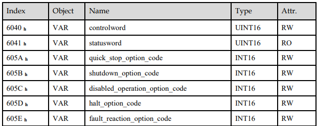
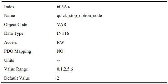
Driver will halt by following settings (605A h: quick_stop_option_code) when this bit is 0.
Bit7: Warning
Driver detects alarm when this bit is 1.
Bit9: Warning
Servo can deal with Controlword when the enabling state of this bit is at 1.
Bit10: Target reached
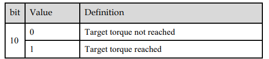
In different control modes the meaning of this bit is different.
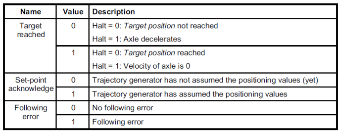
In profile position mode, when set position is reached, this bit is set. When Halt is booted, speed is reduced to 0 and this bit will be set. When new position is set, this bit will be cleared.
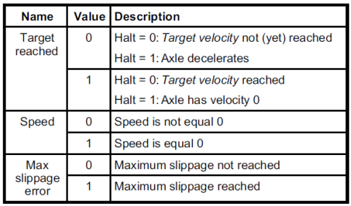
In profile Velocity Mode, when the speed reaches the targeted speed, this bit will be set. When Halt is booted and speed is reduced to 0, this bit is set.
Bit11: Internal limit active
When this bit is 1, it indicates that internal torque has surpassed the set value, or reached the max forward/reverse limit position. It can be confirmed by reading object 60FDh (digital inputs).
Bit12~13
These 2 bits have different meanings in different control mode

Other bits
All reserved.
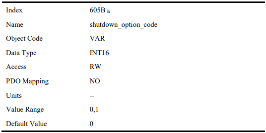
6.5.5 Shutdown_option_code
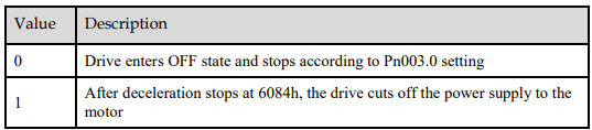
The object shutdown_option_code determines the behavior when the state transition from OPERATION ENABLE to READY TO SWITCH ON is executed.
6.5.6 Disable_operation_option_code
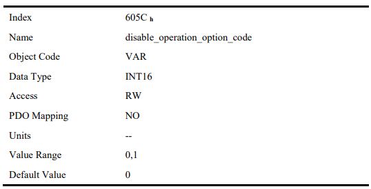
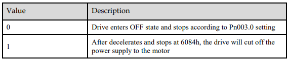
The object disable_operation_option_code determines the behavior if the state transition from OPERATION ENABLE to SWITCHED ON is executed.
6.5.7 Quick_stop_option_code
The object quick_stop_option_code determines the behavior if the state transition from Operation Enable to Quick Reaction Active is executed.
6.5.8 Halt_option_code
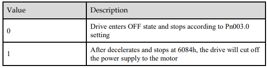
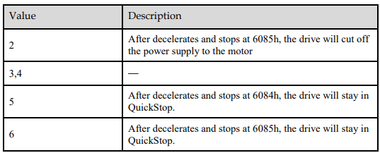
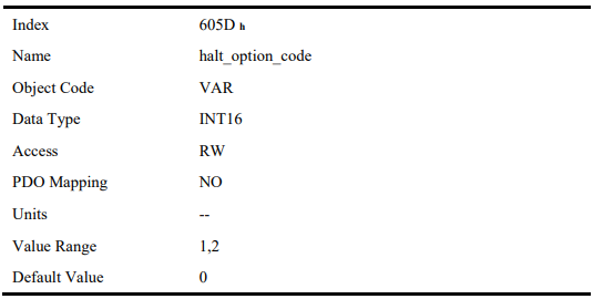
halt_option_code determines how to stop when bit.8 (halt) of controlword is set to 1.

6.5.9 Fault_reaction_option_code
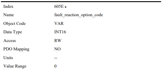
When an error is occurred, fault_reation_option_code determines how to stop.


6.6 Control Mode
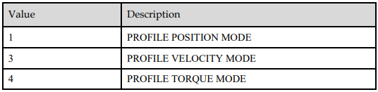
ProNet/EDS/ETS currently supports 5 control modes in CANopen DSP402:
HOMING MODE
PROFILE VELOCITY MODE
PROFILE TORQUE MODE
PROFILE POSITION MODE
INTERPOLATED POSITION MODE
Relevant parameter of control mode

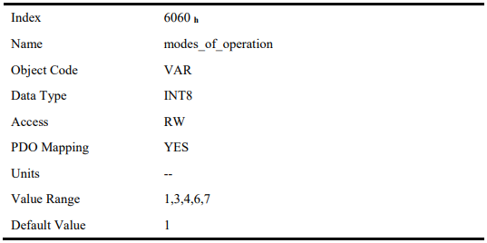
Modes_of_operation
Drive control mode will be determined by parameters of modes_of_operation.

Modes_of_operation_display
Drive current control mode could be read from parameters in modes_of_operation_display.
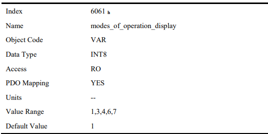
[Note] The current control mode could be only known from parameters in modes_of_operation_display.
6.7 HOMING MODE
Servo drive currently supports multiple homing mode, and users could choose the suitable homing mode.
The user can determine the way of homing, and its velocity and acceleration. After the servo controller has found its reference, the current position is displayed as the value set by home_offset (607C h).
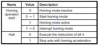
6.7.1 Control word of homing mode

*: Refer to previous chapters
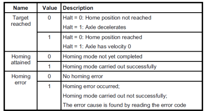
6.7.2 Status word of homing mode
 *: Refer to previous chapters
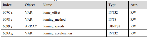
home_offset
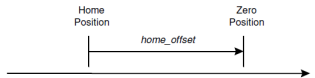
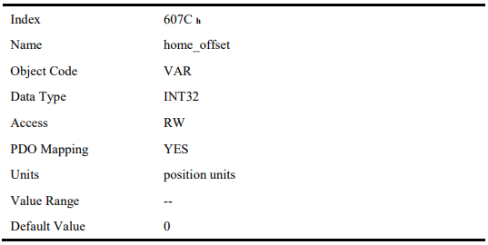
The parameter home_offset determines the distance between the reference position and the zero position.
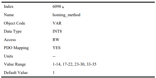
homing_method
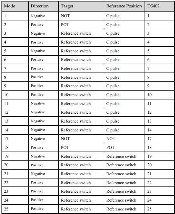
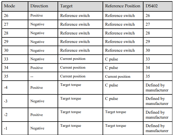
4 kinds of signals can be used as the homing signal: positive limit switch, negative limit switch, reference switch and C pulse.
List of Homing Modes
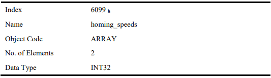
homing_speeds
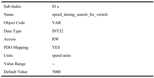
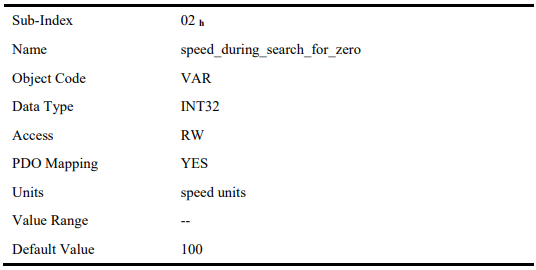
Two kinds of speed are required to find reference point, speed during search for switch and speed during search for zero.
Pn207 (stopper torque)
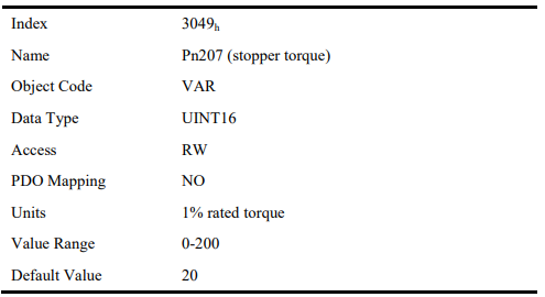
The locked-rotor torque value used by the homing modes -4, -3, -2 and -1. When the machine hits the stop and reaches the torque value set by Pn207 and keeps the filter time set by Pn208, find the C pulse in the reverse direction or make the current position for the origin.
Pn208 (blocking time)
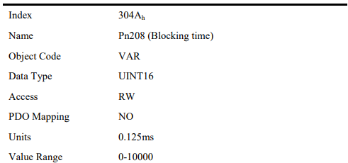
The locked-rotor torque value used by the homing modes -4, -3, -2 and -1. When the machine hits the stop and reaches the torque value set by Pn207 and keeps the filter time set by Pn208, find the C pulse in the reverse direction or make the current position for the origin.

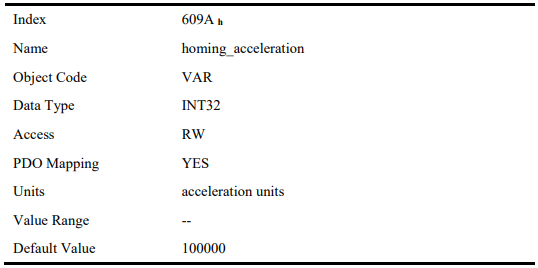
homing_acceleration
The objects homing_acceleration determine the acceleration and deceleration during homing.
6.7.4 Homing Methods
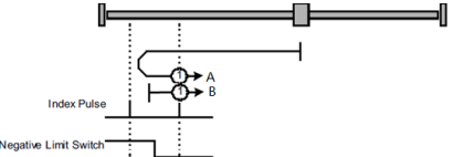
Method 1: Using C pulse and negative limit switch
A: When homing mode is enabled, if negative limit switch N-OT=0, the drive first moves quickly to the negative direction and stops until it reaches the rising edge of negative limit switch (N-OT). Afterwards the drive slowly returns, and stops until reaches the 1st C pulse of falling edge of negative limit switch (N-OT).
B: When homing mode is enabled, if negative limit switch N-OT=1, the drive first moves slowly to the positive direction, and stops until reaches the 1st C pulse of falling edge of negative limit switch (N-OT).
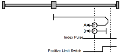
Method 2: Using C pulse and positive limit switch
A: When homing mode is enabled, if positive limit switch P-OT=0, the drive first moves quickly to the positive direction, and stops until it reaches the rising edge of positive limit switch (P-OT). Afterwards the drive slowly returns, and stops until reaches the 1st C pulse of falling edge of positive limit switch (P-OT).
B: When homing mode is enabled, if positive limit switch P-OT=1, the drive first moves slowly to the negative direction, and stops until reaches the 1 st C pulse of falling edge of positive limit switch (P-OT).
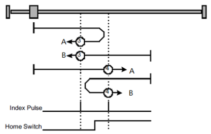
Methods 3 and 4: Using C pulse and positive reference switch
Method 3
A: When homing mode is enabled, if positive reference switch H-S=0, the drive first moves quickly to the positive direction, and stops until it reaches the 1st C pulse of rising edge of positive reference switch (H-S). Afterwards the drive slowly returns, and stops until reaches the 1st C pulse of falling edge of positive reference switch (H-S).
B: When homing mode is enabled, if positive reference switch H-S =1, the drive first moves slowly to the negative direction, and stops until reaches the 1st C pulse of falling edge of positive reference switch (H-S).
Method 4
A: When homing mode is enabled, if positive reference switch H-S =0, the drive first moves slowly to the positive direction, and stops until reaches the 1st C pulse of falling edge of positive reference switch (H-S).
B: When homing mode is enabled, if positive reference switch H-S=1, the drive first moves quickly to the negative direction, and stops until it reaches the 1st C pulse of falling edge of positive reference switch (H-S). Afterwards the drive slowly returns, and stops until reaches the 1st C pulse of rising edge of positive reference switch (H-S).
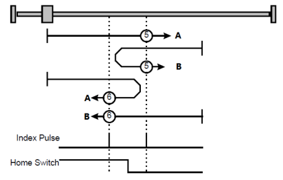
Methods 5 and 6: Using C pulse and negative reference switch
Method 5
A: When homing mode is enabled, if negative reference switch H-S=1, the drive first moves slowly to
the positive direction, and stops until it reaches the 1st C pulse of falling edge of negative reference
switch (H-S).
B: When homing mode is enabled, if positive reference switch H-S =0, the drive first moves quickly to
the negative direction, and stops until reaches the 1st C pulse of rising edge of negative reference switch (H-S). Afterwards the drive slowly returns, and stops until reaches the 1st C pulse of falling edge of negative reference switch (H-S).
Method 6
A: When homing mode is enabled, if negative reference switch H-S =1, the drive first moves quickly to the positive direction, and stops until reaches the 1st C pulse of falling edge of negative reference switch (H-S). Afterwards the drive slowly returns, and stops until reaches the 1st C pulse of falling edge of negative reference switch (H-S).
B: When homing mode is enabled, if negative reference switch H-S=0, the drive first moves slowly to the negative direction, and stops until it reaches the 1st C pulse of rising edge of negative reference switch (H-S).
Methods 7~14: Using reference switch , limit switch and C pulse
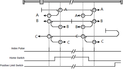
Methods 7~14 use the reference switch which is only active over parts of the travel.
When the positive limit switch (POT) is used for homing, the initial direction of methods 7~10 is the positive direction
− Method 7
A: When homing mode is enabled, if reference switch H-S=0, the drive first moves quickly into the positive direction, but not reaches positive limit switch, and stops until it reaches the rising edge of reference switch (H-S). Afterwards the drive slowly returns, and stops until reaches 1st C pulse of the falling edge of reference switch (H-S).
B: When homing mode is enabled, if reference switch H-S =1, the drive first moves slowly into the negative direction, and stops until reaches 1st C pulse of the falling edge of reference switch (H-S).
C: When homing mode is enabled, if reference switch H-S=0, the drive first moves quickly into the positive direction, reaches positive limit switch, and moves quickly to the negative direction. When it reaches the rising edge of the reference switch (H-S), it starts to decelerate and continues to run in the negative direction, and stops when it reaches the 1st C pulse after the falling edge of the reference switch (H-S).
− Method 8
A: When homing mode is enabled, if reference switch H-S=0, the drive first moves quickly into the positive direction, but not reaches positive limit switch, and slows down until it reaches the rising edge of reference switch (H-S). Afterwards it moves to positive direction, and stops until finds the 1 st C pulse.
B: When homing mode is enabled, if reference switch H-S =1, the drive first moves slowly to the negative direction, and turn around until reaches the falling edge of reference switch (H-S). Then moves slowly into the positive direction, and stops when it reaches the 1st C pulse after the rising edge of the reference switch (H-S).
C: When homing mode is enabled, if reference switch H-S=0, the drive first moves quickly to the positive direction , and reaches positive limit switch; then it moves quickly into th negative direction, and slows down after reaching the rising edge of reference switch (H-S). Afterwards it moves to negative direction, and returns to positive direction slowly. It stops until reaches the 1st C pulse of the rising edge of reference switch (H-S).
Method 9
A: When homing mode is enabled, if reference switch H-S=0, the drive first moves in the positive direction quickly, but not reaches the positive limit switch, and it slowly down after reaching the rising edge of the reference switch (HS), and continues to run slowly in the positive direction. Afterwards it slows down and stops after reaching the falling edge of the reference switch (HS). Then the drive returns slowly, and stops when it reaches the 1st C pulse behind the rising edge of the reference switch (HS).
B: When homing mode is enabled, if reference switch H-S =1, the drive runs slowly in the positive direction directly, reverses after reaching the falling edge of the reference switch (H-S). Afterwards it moves slowly in the negative direction, and stops after it reaches the 1st C pulse of the rising edge of the reference switch (H-S).
C: When homing mode is enabled, if reference switch H-S=0, the drive moves in the positive direction first, and when it reaches the positive limit switch, the drive automatically runs in the reverse direction at a high speed. After reaching the rising edge of the reference switch (HS), it slows down and continues to move slowly in the negative direction, and stops until the 1st C pulse is found.
Method 10
A: When homing mode is enabled, if reference switch H-S=0, the drive first moves in the positive direction quickly, but reaches the positive limit switch, and it slows down when reaching the rising edge of the reference switch (HS), and continues to run slowly in the positive direction. Afterwards it continues to run in the positive direction after reaching the falling edge of the reference switch (HS), and stops until the 1st C pulse is found.
B: When homing mode is enabled, if reference switch H-S =1, the drive runs slowly in the positive direction, and stops at the 1st C pulse behind the falling edge of the reference switch (H-S).
C: When homing mode is enabled, if reference switch H-S=0, the drive moves in the positive direction first, and when it reaches the positive limit switch, the drive automatically runs in the reverse direction at a high speed. After reaching the rising edge of the reference switch (HS), it slows down and stops, and then returns slowly, and continues to move slowly in the positive direction. It stops after reaching the 1st C pulse of the falling edge of the reference switch (H-S.
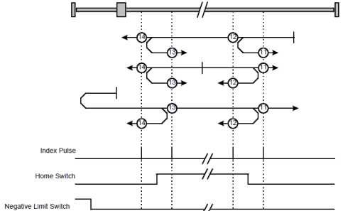
When the negative limit switch (NOT) is used for homing, the method 11~14 is almost same as method 7~10, and the drive first moves to the negative direction.
Methods 17~20, 23~30: Not using C pulse
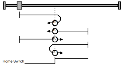
Homing methods 17~30 are similar to methods 1~4, and 7~14, but the target homing position is not relied on C pulse any more but on the change of limit switch or reference point. For example, as below, method 19 and method 20 are just similar to method 3 and method 4.
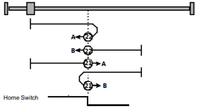
Methods 21, 22 Homing by using reference switch
These two homing methods are similar to 5 and 6, except that the C pulse is not used for target zero position, but depends on the change of the reference switch.
Method 21
A: When homing mode is enabled, if reference switch H-S =1, the drive runs slowly in the positive direction, and stops when it reaches the falling edge of the reference switch (H-S).
B: When homing mode is enabled, if reference switch H-S=0, the drive first moves in the negative direction quickly, slows down and stops when it reaches the rising edge of the reference switch (HS), then the drive returns slowly and runs in the positive direction. It stops when reaching the falling edge of the reference switch (HS).
Method 22
A: When homing mode is enabled, if reference switch H-S =1, the drive first moves in the positive direction quickly, slows down and stops when it reaches the falling edge of the reference switch (HS). Afterwards it returns slowly, runs in the negative direction, and stops when reaching the rising edge of the reference switch (HS).
B: When homing mode is enabled, if reference switch H-S=0, the drive runs slowly in the negative direction, and stops when reaching the rising edge of the reference switch (H-S).
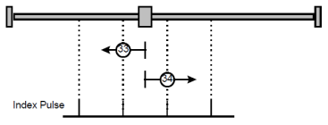
Methods 33 and 34: Homing by using C pulse
Method 33: The drive moves slowly into the negative direction, and stops when reaching the 1st C pulse.
Method 34: The drive moves slowly into the positive direction, and stops when reaching the 1st C pulse.
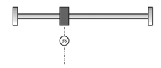
Method 35: Homing on the current position
In this method, the current position shall be taken to be the home position.
Method-4: Movement in positive direction, hitting an end and reversing to travel, the target homing position is the C pulse
In this method, the motor moves in positive direction. When it hits an end so that the torque set in Pn207 is reached for the blocking time set in Pn208, movement in the opposite direction, and the target homing position is the first C pulse.
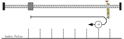
Movement in negative direction, hitting an end and reversing to travel, the target homing position is the C pulse
In this method, the motor moves in negative direction. When it hits an end so that the locked-rotor torque set in Pn207 is reached for the blocking time set in Pn208, movement in the opposite direction, and the target homing position is the first C pulse.
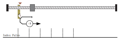
Method -2: Movement in positive direction, hitting an end, makes the current position for the homing point
In this method, the motor moves in positive direction. When the drive hits an end so that the locked-rotor torque set in Pn207 is reached for the blocking time set in Pn208, and makes the current position for the origin.

Method -1: Movement in negative direction, hitting an end, makes the current position for the homing point
In this method, the motor moves in negative direction. When the drive hits an end so that the locked-rotor torque set in Pn207 is reached for the blocking time set in Pn208, and makes the current position for the origin.

Notes: When starting homing on homing method about input signal, the rotation direction of servo motor is associated with the initial status of the limit switch. Changing the initial status by inverse input, if it is necessary.
6.8 PROFILE VELOCITY MODE
6.8.1 Flow Chart of Profile Velocaity Mode
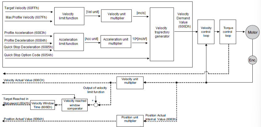
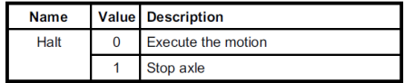
6.8.2 Control Word
 *: Refer to previous chapters
6.8.3 Status Word
 *: Refer to previous chapters
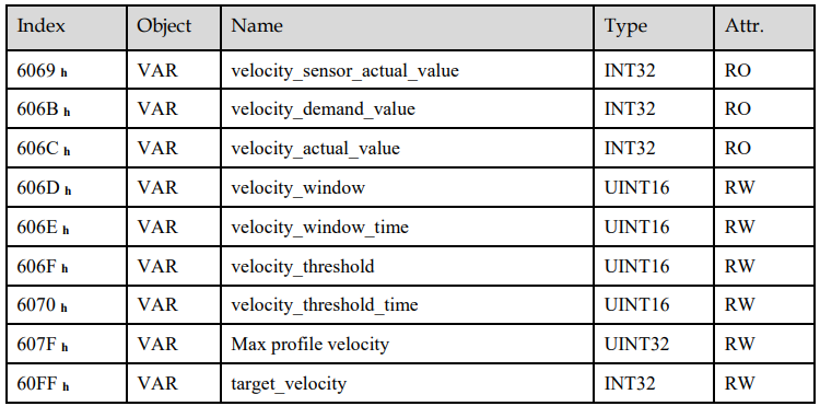
velocity_sensor_actual_value
The master could read velocity_sensor_actual_value to know the current velocity. The parameter’s unit is internal speed unit.
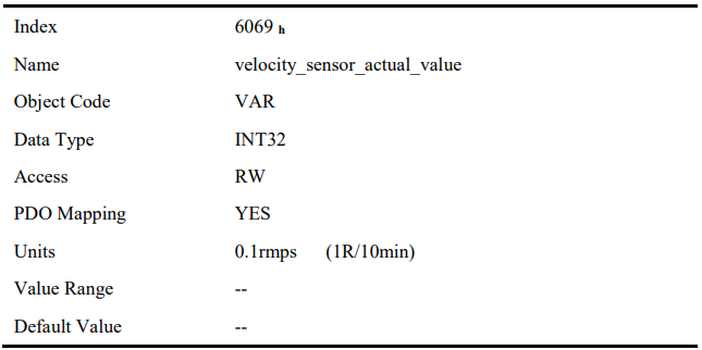
velocity_demand_value
The master can read velocity_demand_value to know the current reference speed value of the servo drive. The unit of this parameter is user’s velocity unit.
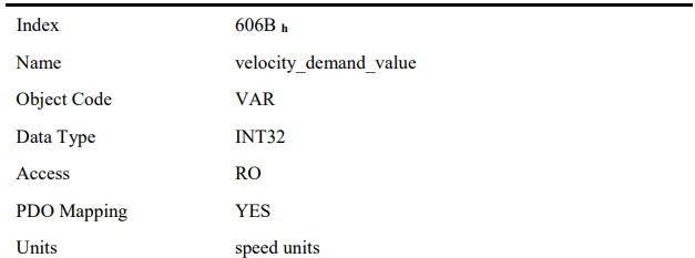

velocity_actual_value
The master can read velocity_ actual _value to know the current velocity of the servo motor. The unit of this parameter is user’s velocity unit.
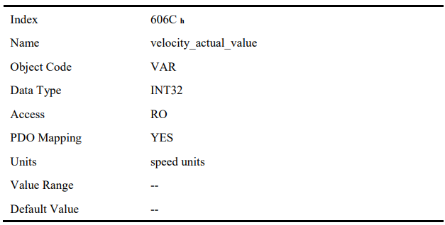
velocity_window
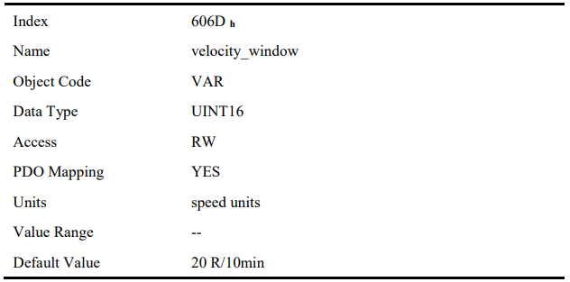
The difference between velocity_actual_value (606C h) and target_velocity (60FF h) is defined as actual velocity error window. If the actual velocity error window is always smaller than velocity_window (606D h) within the time set by velocity_window_time (606E h), then bit 10 of status word (target_reached) will be set to indicate that the set velocity has been reached.
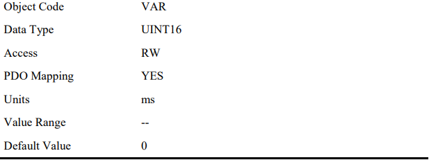
velocity_window_time
Velocity window comparator is composed of velocity_window_time and velocity_window.

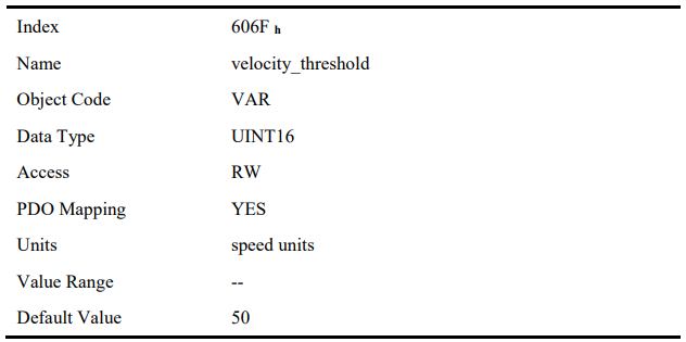
velocity_threshold
Velocity_threshold indicates a range close to zero speed in order to define if the servo motor has already stopped.
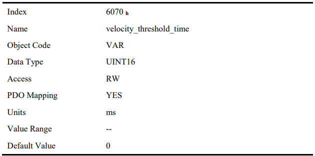
velocity_threshold_time
Velocity_threshold_time is used to set the shortest time when servo motor’s speed is under velocity threshold. The unit is: ms. When the time that servo motor’s speed is lower than the threshold is more than velocity_threshold_time, status word bit 12 (speed is zero) will be set as 1.
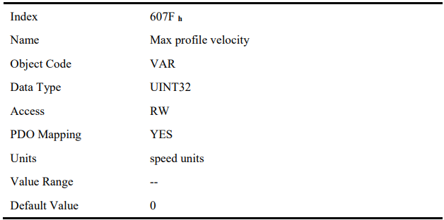
Max profile velocity
The object max profile velocity is the speed that the motor cannot exceed. Its unit is the unit of customer’s speed.
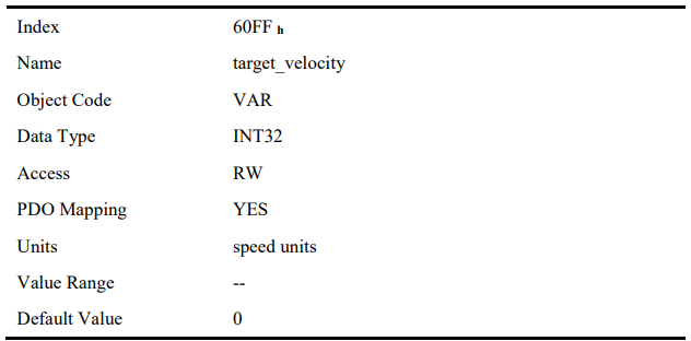
target_velocity
target_velocity is the reference speed.
6.9 PROFILE TORQUE MODE
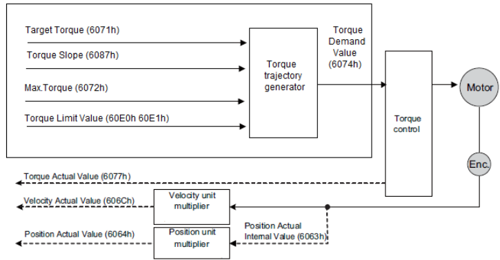
6.9.1 Flow Chart of PROFILE TORQUE MODE
6.9.2 Control Word


6.9.3 Status Word

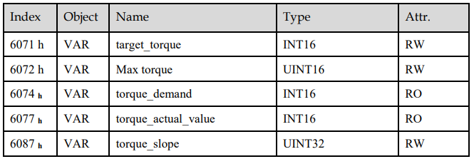
target_torque
The master can send a torque reference to the drive through target_torque, the unit is 0.1% of the rated motor torque, which is indicated on the motor nameplate.
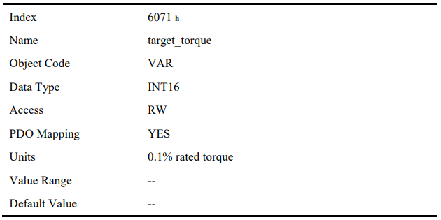
Max torque
Max torque, the maximum torque allowed by the motor during operation, the unit is 0.1% of the rated torque of the motor.
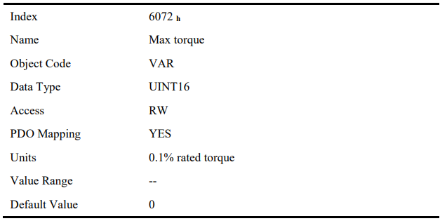
torque_demand
The output of the torque reference generator. The drive generates the command slope according to the value of target_torque and torque_slope.
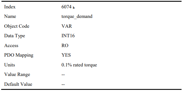
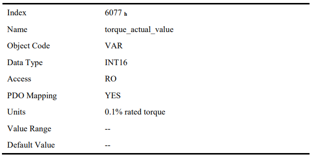
torque_actual_value
The master can get the current output torque of the motor by reading torque_actual_value. Its unit is 0.1% of rated torque of the motor.
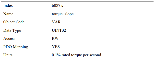
torque_slope
The master can set the change speed of torque reference via torque_slope. Its unit is 0.1% of rated torque per second.

6.10 PROFILE POSITION MODE
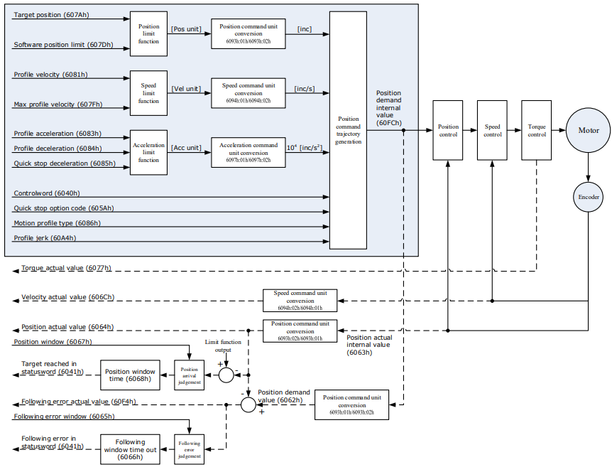
6.10.1 Flow Chart of PROFILE POSITION MODE
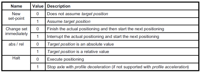
6.10.2 Control Word

6.10.3 Staus Word

target_position
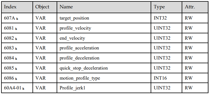
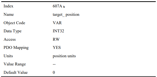
The object target_position is the given target position, which (target_position) is interpreted either as an absolute or relative position. This depends on bit 6 (relative) of the object control word.
profile_velocity
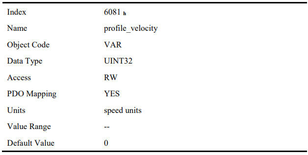
The object profile_velocity specifies the speed that usually is reached during a positioning motion at the end of the acceleration ramp.
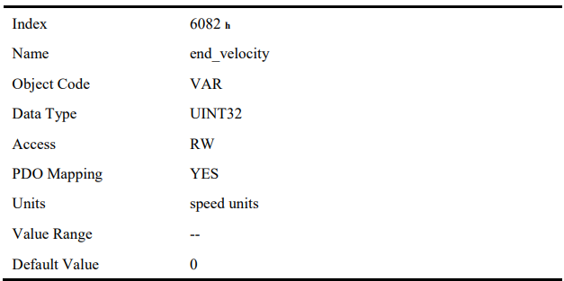
end_velocity
End_velocity is the speed when servo motor reaches the target_position. Normally we set this value as 0 in order to stop the servo motor when the servo motor reaches the requested position. But in continuous multiple position, this value could be set as a non-zero value.
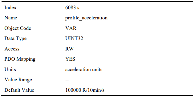
profile_acceleration
Profile_acceleration is the acceleration speed before reaching the target position
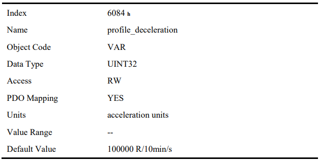
profile_deceleration
Profile_deceleration is the deceleration speed before reaching the target position.
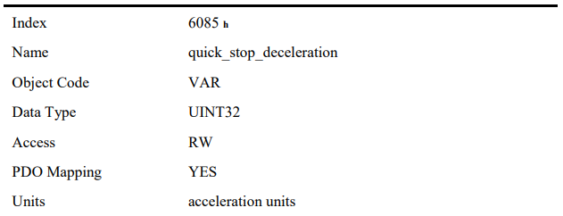
quick_stop_deceleration
Quick_stop_deceleration is the deceleration speed in Quick Stop.

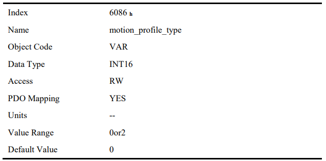
motion_profile_type
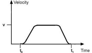
Motion_profile_type is used to select the motion curve. Now we only support trapezoid speed curve (set as 0) and S speed curve (set as 2).
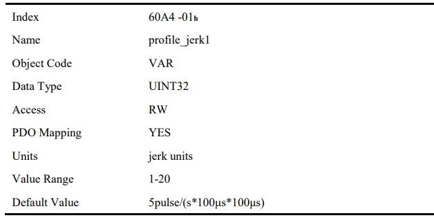
profile_jerk1
Profile_jerk1 is used to set the jerk of speed profile. The value is smaller, the speed changing is more smooth
6.10.5 Function Description
When the speed profile is trapezia (motion_profile_type=0), two different ways to apply target positions are supported:
Single-step
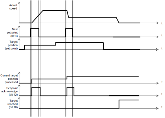
When the current position is being executed, the controller resends a new position, and at the same time gives a rising edge to bit4 of the controlword, the drive then will re-plan and execute based on the latest position and speed
Continuous-step
After the motor reaches the target position, the drive informs the host of "target position reached", and then gets a new target position and starts motion. Before getting a new target position, the motor speed is usually zero.
Both of the above two methods can be changed in real time by bit4 and bit5 of the controlword and bit12 (set_point_acknowledge) of the status word statusword. The position control being executed can be interrupted through the handshake mechanism, and the target position can be reset by using these few words.
Single-step setting procedure
1. Set the NMT status into Operational and set the control mode parameter (6060 h) as 1.
2. According to the actual demand, we could set the target position (target_positon: 607A h) and so on.
3. We need set bit4 (new_set_point) of the control word as 1, bit 5 (change_set_immediately) as 0, bit 6 (absolute/comparative) should be determined by whether the reference target position is an absolute value or a comparative value.
4. We use bit12 (set_point_acknowledge) of the status word to configure the servo drive acknowledge mechanism. And then we start to operate position control.
5. After reaching the target position, servo drive will need to respond through bit 10 (target_reached) of the status word. And then servo drive will follow the program to keep moving or accept new target position.
Continuous-step setting procedure
6. At first, set NMT as Operational and control mode parameter (6060 h) as 1.
7. According to actual demand, set the first target position (target_position: 607A h), target speed, acceleration/deceleration and other Related Parameters.
8. Set bit 4 (new_set_point) of control word as 1. Set bit 5 (change_set_immediately) as 0. Set bit6 (absolute/comparative) according to the type of object position.
9. Set bit 12 (set_point_acknowledge) of the status word and then start to operate position control.
10. Set the second target position (target_position: 607A h), target speed, acceleration/deceleration speed.
11. Set bit4 (new_set_point) as 1, bit 5 (change_set_immediately) as 0. Set Bit6 (absolute/comparative) according to the target position type.
12. After reaching the first target position, the servo drive will not stop and keep moving toward the second target position. After reaching the second target position, the servo drive will respond through status word bit 10 (target_reached). Then the servo motor will follow the program to keep moving or accept new target position.
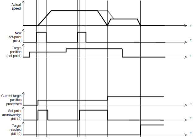
When the speed profile is S (motion_profile_type=2), only Continuous-step setting is available. 6083h (profile_acceleration) limits max acceleration, and 6081h (profile_velocity) limits max speed. 60A4-01 h (VAR Profile_jerk1) limits the jerk. Only symmetrical S linear is available currently
6.11 INTERPLATION POSITION MODE
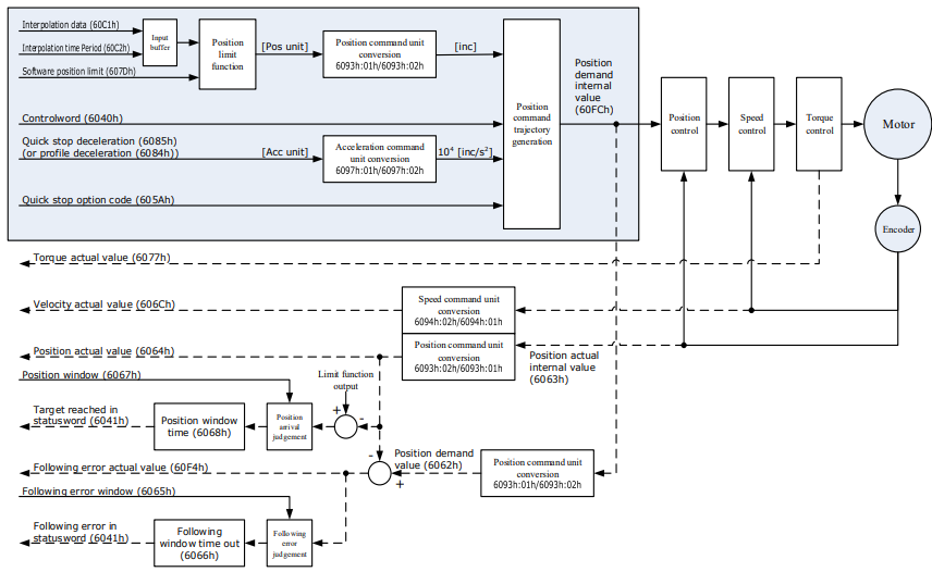
6.11.1 Flow Chart of INTERPLATION POSITION MODE
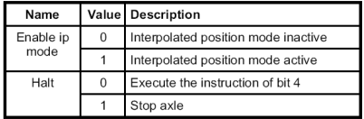
6.11.2 Control Word

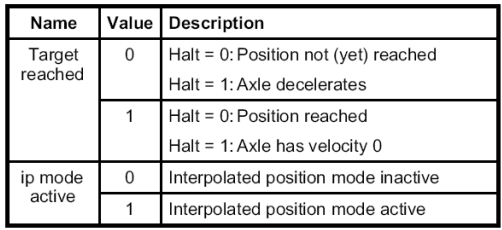
6.11.3 Status Word

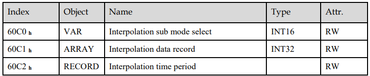
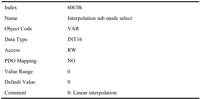
Interpolation sub mode select
Interpolation sub mode select is used to select the method of interpolation under IP control. Only the linear interpolation is available.
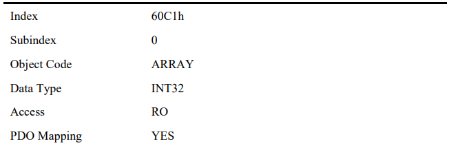
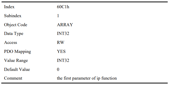
Interpolation data record
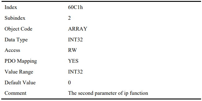
Interpolation data record is used to reserve interpolation potion data. Our servo drive’s interpolation command only uses the first data whose subindex is 1.

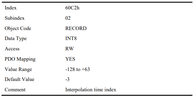
Interpolation time period
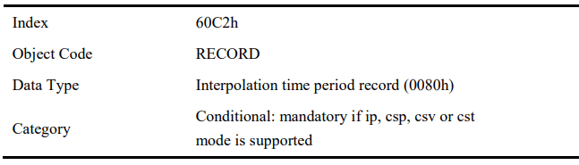
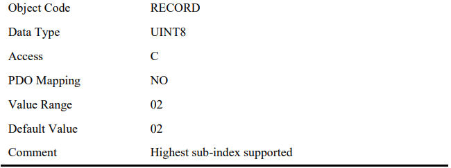
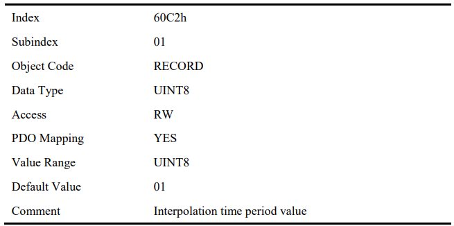
Interpolation time period is used to reserve the time data of interpolation position.

6.11.5 Functional Description
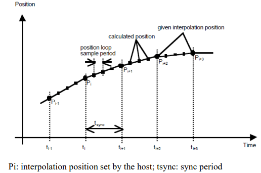
Interpolation principle of IP mode:
Explanations
1. In our servo drive, there is no buffer for position data so in IP control, all the position data needs to be updated by the host controller. To achieve synchronization, host controllers need to send the updated position at first and then use SYNC signal to make all the servo drive receive the synchronization information. After receiving the synchronization information, servo drive will synchronize its internal clock. Please notice that the sync period should be not bigger than interpolation cycle period in order to keep the updating of interpolation data.
2. In IP mode, the host controller should at first set the servo’s PDO receiving method into sync mode (use SYNC frame to receive and send synchronization information). Since the SYNC is broad casted, each servo drive will only update PDO data after receiving this signal.
3. Before SYNC is sent, host controller should send position data Xi and Controlword to the servo drive.
4. When there is data delay, servo drive will use the last sync date to do interpolation.
5. After one IP period is ended, if there is no further data updating, interpolation cycle overtime alarm (A 69) will happen. Then servo drive will stop.
Recommended RPDO configuration:
When you use only one RPDO
Control word (index: 6040h, subindex: 0h) 32bit position reference (index:60C1h,subindex:01h)
When you use two RPDOs
Control word (index:6040h,subindex:0h) 32bit position reference (index:60C1h,subindex:01h)
Configuration process:
1. Configure PDO. (RPDO1 is configured as index: 6040h, subindex: 0h, RPDO2 is configured as index 60c1h, subindex: 1h)
2. Set interpolation cycle (60C2-01h), in micro second (ms).
3. Set PDO as Sync mode (Set the object dictionary (index: 1400h, subindex: 02h) as 1. Set object dictionary (index: 1401h, subindex: 02h) as 1). If sending PDO needs to be in sync mode as well, we need to set object dictionary (index: 1800h, subindex: 02h) as 1 and (index:1801h,subindex:02h) as 1 as well.
4. Set the control mode to PI mode (set the object dictionary (index: 6060h, subindex:0h) to 7);
5. NMT starts node.
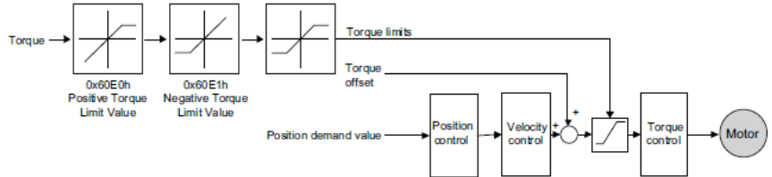
6.12 Torque Limit Function
In CANOPEN bus mode, torque limit function is restricted by 0x60E0 and 0x60E1 as below
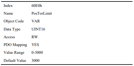
PosTorLimit(0x60E0)
PosTorLimit is the positive torque limit, unit: 0.1% rated torque
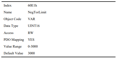
NegTorLimit(0x60E1)
NegTorLimit is the negative torque limit, unit: 0.1% rated torque
6.13 DIGITAL INPUT /OUTPUT
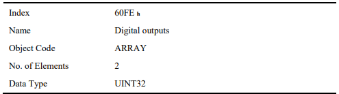
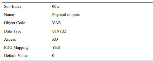
60FE (Physical outputs)
In some cases, some switches (i.e. the origin signal and limit signal) are not sent to the servo drive directly, but sent by the host. You need to use the object 60FE-01h (Physical outputs) to transfer the relevant signals.
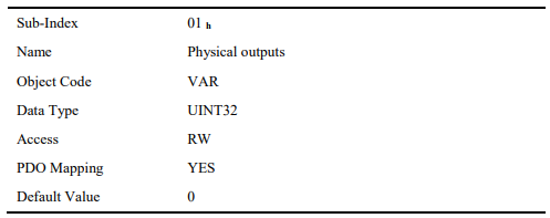
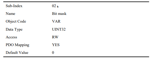

The bit28-bit30 bits of this object correspond only to the input port of CN1 respectively, and then you need to configure the corresponding function of the input port through Pn511 or invert it through 517.
60FD (Physical outputs)
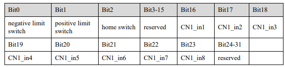
Sometimes, the host controller may read the object 60FDh (Digital Inputs) to monitor the switching onoff inputs of the drive, which are defined as follows:


6.14 Functions of TouchProbe
You may use the following trigger events to latch the feedback motor position.
TouchProbe input 1 (TP1) triggered
TouchProbe input 2 (TP2) triggered
Trigger by using C pulse signal
The latch function of two TouchProbes can be used at the same time:
Latch control object: 60B8h (bit0 to bit7)
Latch state object: 60B9h (bit0 to bit7)
The locked position is always stored in the TouchProbe1 position value (60BAh and 60BBh).
Trigger signal: C pulse signal or EXT1 signal of the encoder
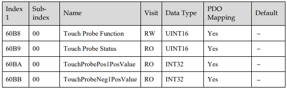
The objects involved in this function are listed in table below:

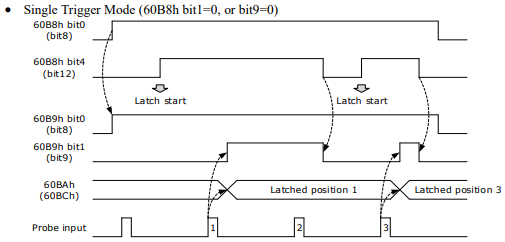
Example of the execution process of Touch Probe:
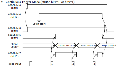
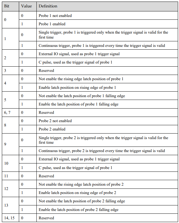
60B8h: Touch Probe Function
The object is configured to the Touch Probe Function.

Each bit of Touch Probe Function (60B8h) is described as follows:
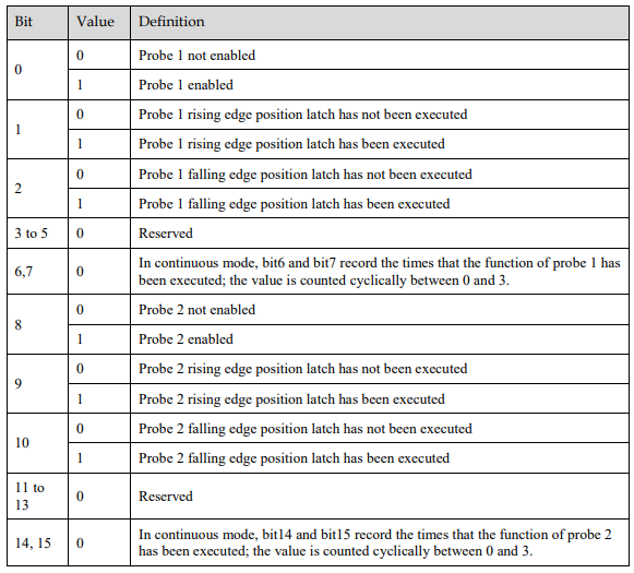
60B9h: Touch Probe Status
Touch Probe Status (60B9h) indicates the touch probe status.

Each bit of Touch Probe Function (60B9h) is described as follows:
60BAh: TouchProbePos1PosValue
TouchProbePos1PosValue (60Bah) indicates the latch location when the Touch Probe1 trigger condition occurs.

60BBh: TouchProbeNeg1PosValue
TouchProbeNeg1PosValue (60BBh) indicates the latch location when the trigger condition for Touch Probe1 falling edge occurs.

60BCh: TouchProbePos2PosValue
TouchProbePos2PosValue (60BCh) indicates the latch location when the Touch Probe2 trigger condition occurs.

60BDh: TouchProbeNeg2PosValue
TouchProbeNeg2PosValue (60BDh) indicates the latch location when the trigger condition for Touch Probe2 falling edge occurs.

Pn331 and Pn332
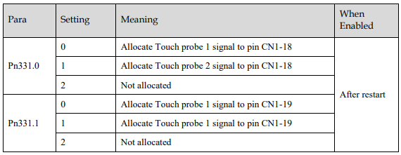
You can allocate the TouchProbe functions by Pn331, and set Touch Probe Digital Input Filtering Time by Pn332. The Related Parameters are as following:
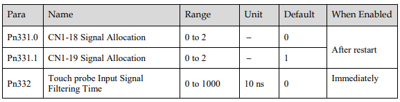
The signal allocation instructions for Touch probe 1 and Touch probe 2 are listed in table below.
Pn333
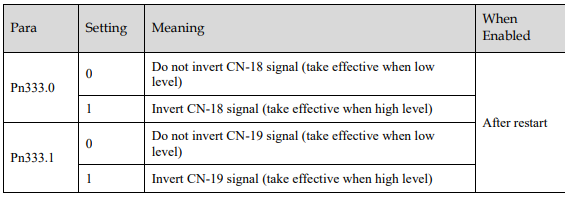
You can select whether to invert the Touch Probe 1 and Touch Probe 2 signals through the parameter Pn333. In general, it needs to be set according to the actual input signal level.
6.15 Soft Limit Function
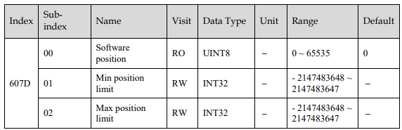
Software Position Limit defines the maximum and minimum absolute position commands. Every target position is checked against these limits. The limit positions are specified in user-defined position reference units, the same as for target positions, and are always relative to the machine home position. Before comparing with Target position, you need to use Home Offset to correct the position limit.
corrected min position limit = min position limit - home offset
corrected max position limit = max position limit - home offset
The software position limits are enabled at the following conditions:
When homing is completed
corrected min position limit<corrected max position limit
When the servo is not homed, if min position limit<max position limit, the servo takes max position limit and min position limit as the position limit; otherwise, the position command is not restricted by the position limit.