
8. Tuning
8.1 Overview
8.1.1 Basic Conception
Tuning is the process of satisfying the servo performance by adjusting the parameters involved in the
control law.
Tuning Flow
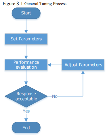
The process of tuning is usually an iterative process, and Figure 8-1 shows the general flow.
Parameter Classification
There are two types of parameters in the tuning.
Function Parameters: refers to some application function selections or switches that may improve Servo performance.
Adjustment Parameters: increasing or decreasing these parameters may improve Servo performance.
Servo Performance
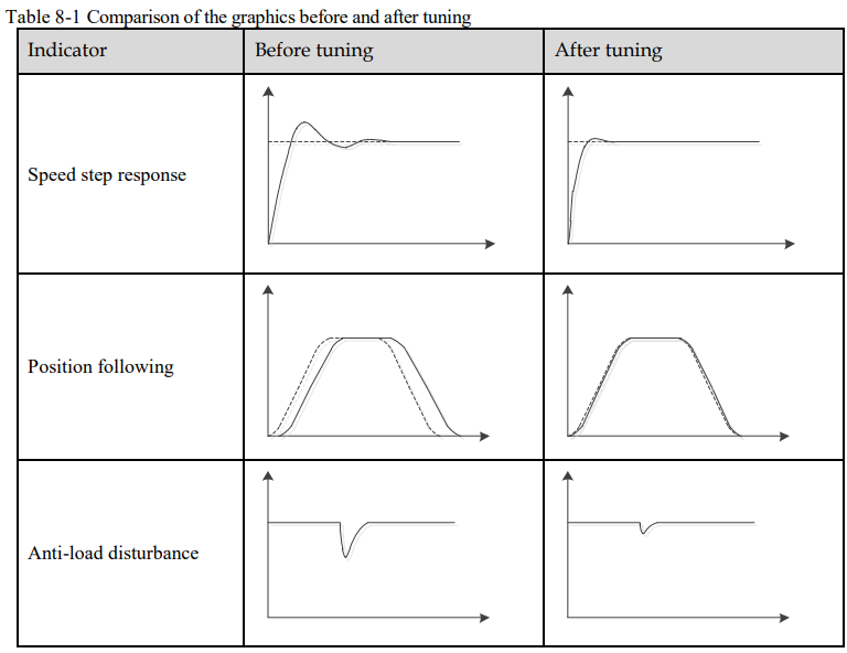
In general, the indicators used to evaluate Servo performance are bandwidth, response time, overshoot, steady state error, anti-load disturbance, speed ripple fluctuation, torque ripple, and so on. Table 8-1 shows the comparison of the graphics before and after tuning in the example indicators.
8.1.2 Control Block Diagram
It is necessary to learn the Servo control principle and Figure 8-2 shows the Servo control block diagram. The position loop, the speed loop and the torque loop are cascade structures, corresponding to the position control mode, the speed control mode and the torque control mode respectively
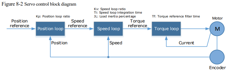
NOTE: only the basic tuning parameters during the tuning are shown in the figure.
8.1.3 Tuning Process
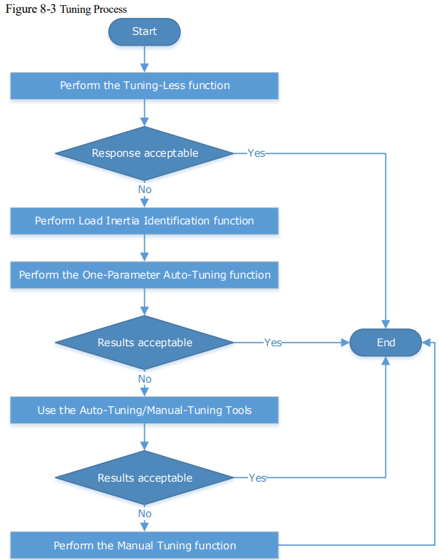
The Drive provides a variety of tuning methods, you can adjust the device according to the process shown in Figure 8-3, in order to obtain the desired Servo performance.

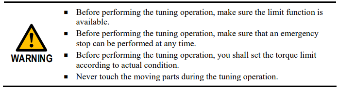
8.1.4 Precautions Before Tuning
8.2 Tuning Modes
8.2.1 Tuning-Less
Function Description
The tuning-less performs auto-tuning to obtain a stable response regardless of the type of machine or changes in the load. Autotuning is started when the Servo is turned ON.
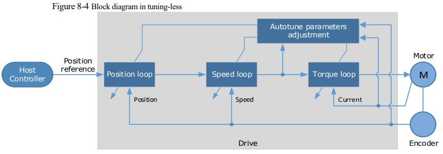
The tuning-less function uses an Autotune parameters adjustment module that updates the position loop and speed loop parameters in real time based on the servo operating state (position, speed, current). Figure 8-4 shows the block diagram in tuning-less.
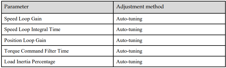
When using the tuning-less function, the following parameters are automatically adjusted
NOTE: The parameters will not change automatically in tuning-less function.
Applicated Case
Applied for that no more than 30 times the load moment of inertia.
Applied for any rotation speed.
Relevant Parameters

Application Restrictions
The following functions or applications are not available in the Tuning-less function:
Gain switch is disabled.
P/PI Switch is disabled.
Speed feedback by using observed speed is disabled.
Load Torque Compensation is disabled.
Model Following Control Function is disabled.
8.2.2 One-Parameter Auto-Tuning
Function Description
This tuning function is similar to the tuning-less function, using an Autotune parameters adjustment module that updates the position loop and speed loop parameters in real time based on the servo operating state (position, speed, current).
Only the parameter Pn101 (Servo Rigidity) needs to set in One-Parameter Auto-Tuning function, and
Figure 8-5 shows the block diagram in One-Parameter Auto-Tuning.
Figure 8-5 Block diagram in One-Parameter Auto-Tuning

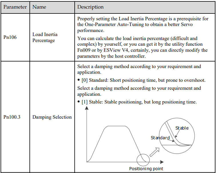
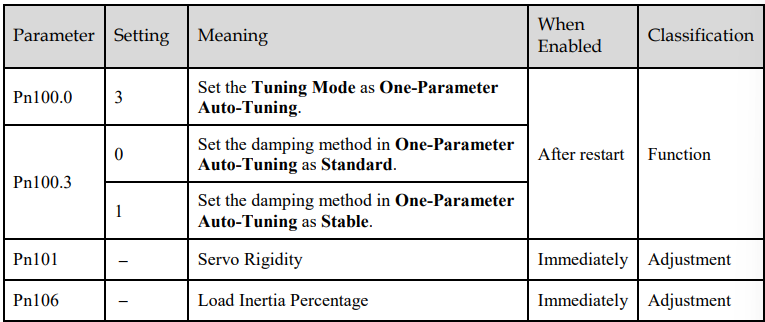
Before performing One-Parameter Auto-Tuning, you need to manually set the following parameters:
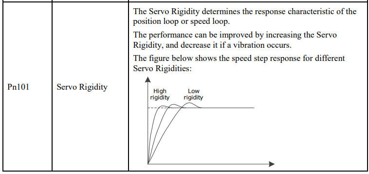
When using One-Parameter Auto-Tuning function, the following parameters are automatically adjusted.
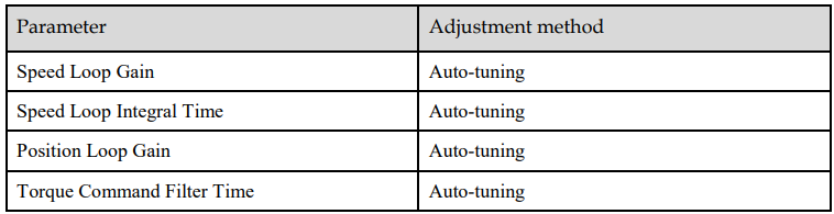 NOTE: The parameters will not change automatically in tuning-less function.
Compared to Tuning-less, there are some features below in One-Parameter Auto-Tuning:
Tuning based on a proper load inertia percentage can get a better servo performance.
The setting of Servo Rigidity can be applied to more operating conditions.
Applicated Case
Applied for that more than 50 times the load moment of inertia.
Applied for any rotation speed.
Relevant Parameters
Application Restrictions
The following functions or applications are not available in One-Parameter Auto-Tuning function:
Gain switch is disabled.
Model Following Control Function is disabled.
8.2.3 Manual Tuning
Function Description
In the Manual Tuning, you need to manually adjust the gain parameters without using the autotune parameter adjustment module, until the Servo get the desired performance. Figure 8-6 shows the block diagram in Manual Tuning.
Figure 8-6 Block diagram in Manual Tuning
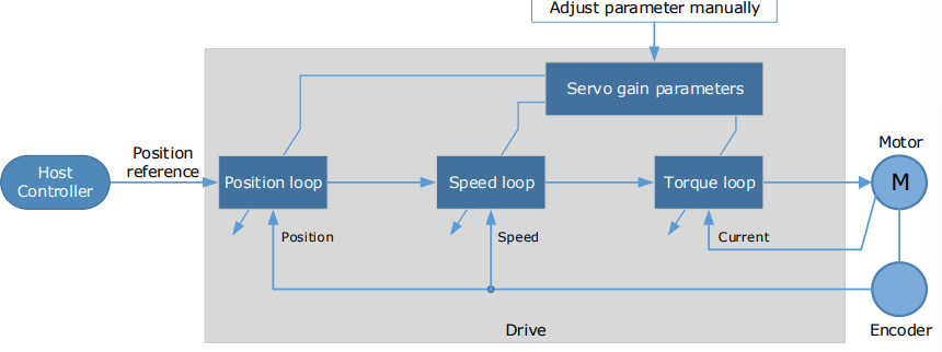
It is necessary to adjust the three-loop control parameters of the Servo from the inside out, that is, the adjustment sequence is Torque loop → Speed loop → Position loop. In addition, in order to meet the stability, the bandwidth setting should be the largest in the torque loop, the speed loop is the second, and the position loop is the smallest.
The following parameters need to be adjusted in each loop when performing Manual Tuning.
Torque loop (Torque Control Mode)
− Torque Reference Filter Time (Tf):
The torque reference filter filters the torque reference to remove the high frequency band, which can effectively reduce the torque ripple of the Motor output, eliminate signal noise and reduce the temperature rise of the Motor. The larger the Torque Reference Filter Time, the better the filtering effect on the torque reference. However, the greater the phase lag, and the slower the torque response. Therefore, a smaller acceptable value should be set to obtain a larger torque loop bandwidth in the actual tuning.
Speed loop (Speed Control Mode)
− Relevant parameter in torque loop (Tf)
− Load Inertia Percentage (JL)
Properly setting the Load Inertia Percentage is a prerequisite for the tuning to obtain a better Servo performance.
You can calculate the load inertia percentage (difficult and complex) by yourself, or you can get it by the utility function Fn009 or by ESView V4, certainly, you can directly modify the parameters by the host controller.
− Speed Loop Gain (Kv), Speed Loop Integral Time (Ti)
The speed loop is controlled using a Proportional-Integral Controller that contains Speed Loop Gain and Speed Loop Integral Time. Both of them determine the speed loop bandwidth and antidisturbance performance of the Servo. In general, if you can increase the setting of the Speed Loop Gain, the speed loop bandwidth will be increased and the anti-load disturbance performance will be better. And, if you can decrease the setting of the Speed Loop Integral Time, the integral action will be stronger, the speed loop bandwidth will be increased, and the anti-load disturbance performance will be better. In addition, the integral action may reduce the steady-state error to zero.
Table 8-2 lists several commonly used adjustment methods based on the characteristics of the speed
step response.
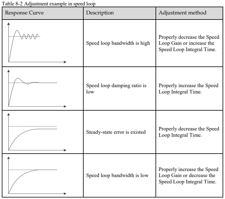
It is recommended to increase the Speed Loop Gain and decrease the Speed Loop Integral Time to obtain a larger speed loop bandwidth.
Position loop (Position Control Mode)
− Relevant parameters in speed loop (Kv, Ti, Tf, and JL)
− Position Loop Gain (Kp)
The position loop is controlled using a Proportional Controller that only contains the Position Loop Gain. This parameter determines the position loop bandwidth. If you increase the Position Loop Gain, the position loop bandwidth will be increased and the anti-load disturbance performance will be better. However, overshooting and vibration in the position reference may be occurred.
It is recommended to set the Position Loop Gain to a quarter of the Speed Loop Gain, and make appropriate adjustments based on this.
Applicated Case
Applied for that more than 50 times the load moment of inertia.
Applied for any rotation speed.
Relevant Parameters
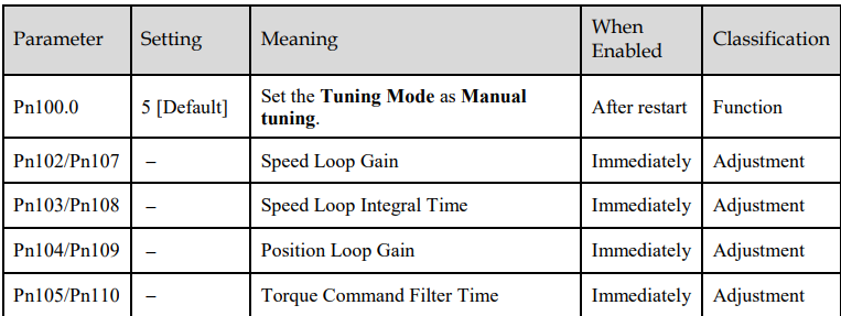
NOTE: the settings of Pn107 to Pn110 are taken effect after the gain is switched.
8.3 Tuning Tools
There is an Auto-Tuning Tool and a Manual Tuning Tool in Tuning tools. When using a tuning tool, the Drive will execute the position references generated internally, Figure 8-5 shows the block diagram in using a tuning tool.
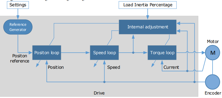
The reference generator plans an appropriate position reference according to the settings of relevant parameter.

8.3.2 Auto-Tuning Tool
Function Description
With the Auto-Tuning Tool, the reference generator can plan the position curve and generate a position reference as inputs to the position loop.
There are two operation patterns (POS0 and POS1), you can set their relevant parameters respectively.Figure 8-8 shows an example of position-speed timing diagram in PJOG operation.
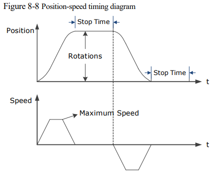
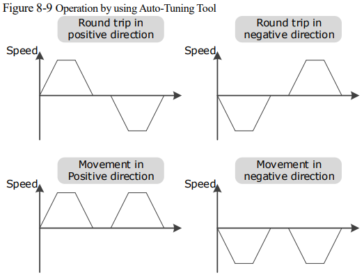
The Drive will operator the Motor repeatedly according to the parameter settings of the two operation patterns until the tuning is completed. You can set the parameters Pn164 and Pn168 to a negative value for reversing the Motor, so that there are four ways of the operation in the program jogging, as is shown in Figure 8-9.
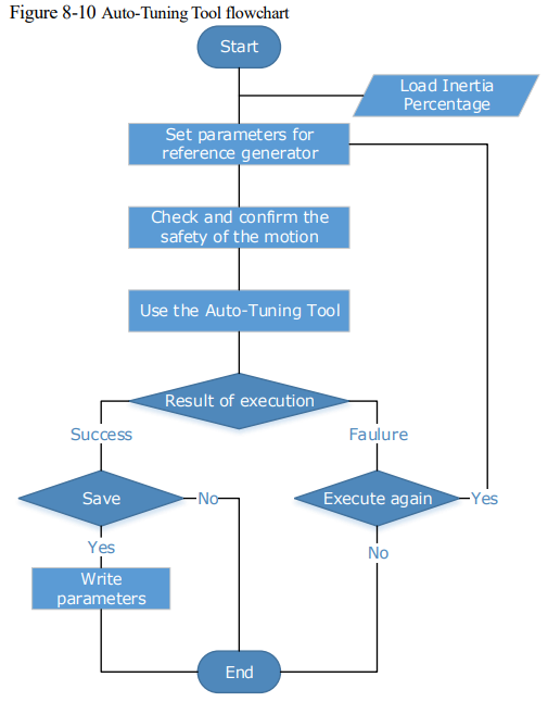
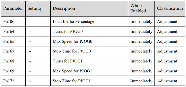
You shall set the Rotations (Pn164 and Pn168) and Max Speed (Pn165 and Pn169) to a proper value. If the Rotations is set too small or the Max Speed is set too large, it is possible that the maximum speed set cannot be reached. In this case, it is necessary to increase the Rotations or decrease the Max Speed. Use the Auto-Tuning Tool as shown inFigure 8-10.
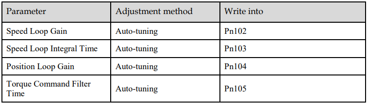
The following parameters are automatically adjusted when using the auto-tuning tool.

Applicated Case
Applied for the high rigidity (up to 20 times load moment of inertia) equipment.
Applied for the low rigidity (up to 10 times load moment of inertia) equipment.
The number of revolutions is more than 1 rotation, and the rotation speed is higher than 100 rpm.
Relevant Parameters
Application Restrictions
You can use the automatic vibration suppression function when using the auto-tuning tool.
The following functions or applications are not available when using Auto-Tuning Tool:
Gain switch is disabled.
Model Following Control Function is disabled.
Notch Filter is disabled.
Vibration Suppression is disabled.
Load Oscillation Suppression is disabled

Operation Procedure: Use the Panel Operator of the Drive
The following are the steps to use the Auto-tuning tool.
Step 1 Press [M] key several times to select the Utility Function Mode.

Step 2 Press [▲] key or [▼] key to select the function number Fn017.
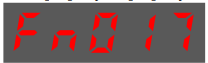
Step 3 Press [◄] key, and Panel Operator displays as below

Step 4 Press [M] key to execute this operation, and Panel Operator display as below.
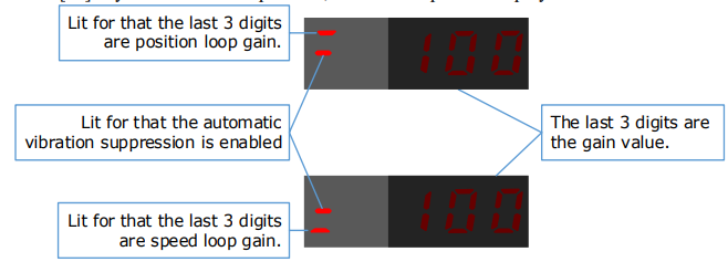
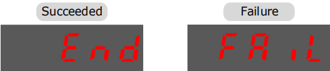
Step 5 When this operation has been completed, Panel Operator will display the result of execution.
Step 6 Press [◄] key to return to the display of the Fn017.
---- End
Operation Procedure: Use the ESView V4
By using the Auto-Tuning Tool, the Drive can automatically perform the round-trip (forward and reverse) operation to adjust for machine characteristics.
Step 1 Select Tuning → Tuning Tools → Auto-Tuning Tool in the Menu Bar of the ESView V4 main windows.
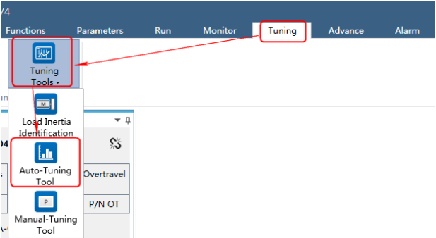
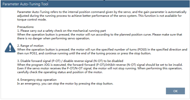
Step 2 Read and follow the precautions in the warning box, and then click OK.
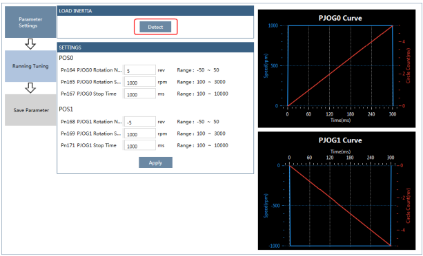
Step 3 The Auto-Tuning Tool window will be displayed in Function Display Area.
Step 4 Click Detect to perform Load Inertia Identification function if necessary.
Step 5 Set the relevant parameters for the operation patterns POS0 and POS1.
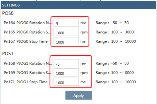
Rotation Number: Set the numbers of rotation the Motor will run in the operation pattern POS0 or POS1.
Rotation Speed: Set the Motor running speed in the operation pattern POS0 or POS1
Stop Time: Set the hold time when the Motor stops running in the operation pattern POS0 or POS1,
and then switches to the other operation pattern.
Step 6 Click Apply to complete the settings.
Step 7 Click Running Tuning.
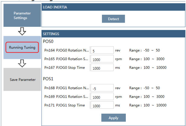
Step 8 The window will display the preparations before running the tuning.
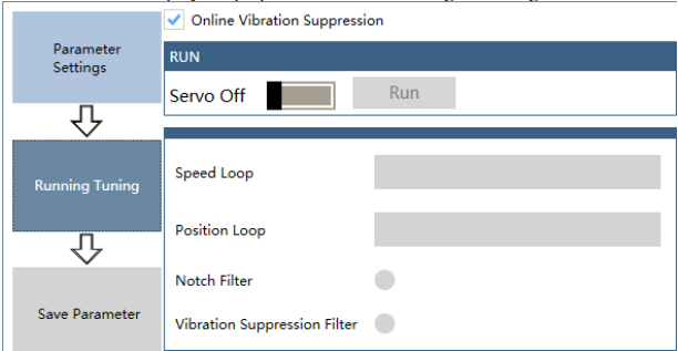
The setting will be written into the Drive automatically after you check or uncheck Online Vibration Suppression option.
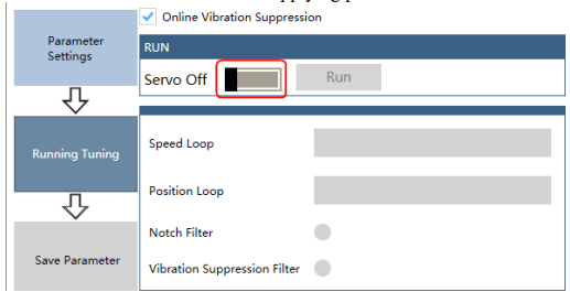
Step 9 Click Servo Off / Servo On for supplying power to the Motor.
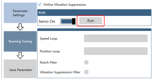
Step 10 Click Run.
Step 11 The Motor will be run between the operation patterns POS0 and POS1
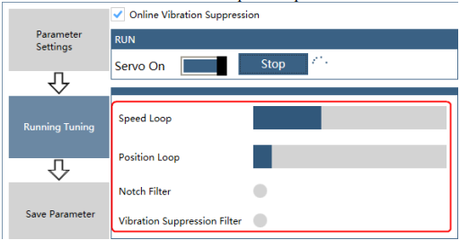
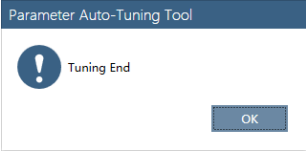
Step 12 Click OK when the Auto-Tuning Tool function has been completed.
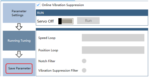
Step 13 Click Save Parameter.
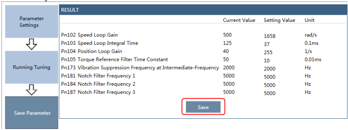
Step 14 Check the RESULT, and click Save, the settings of parameters will be written into the Drive automatically.
---- End
8.3.3 Manual-Tuning Tool
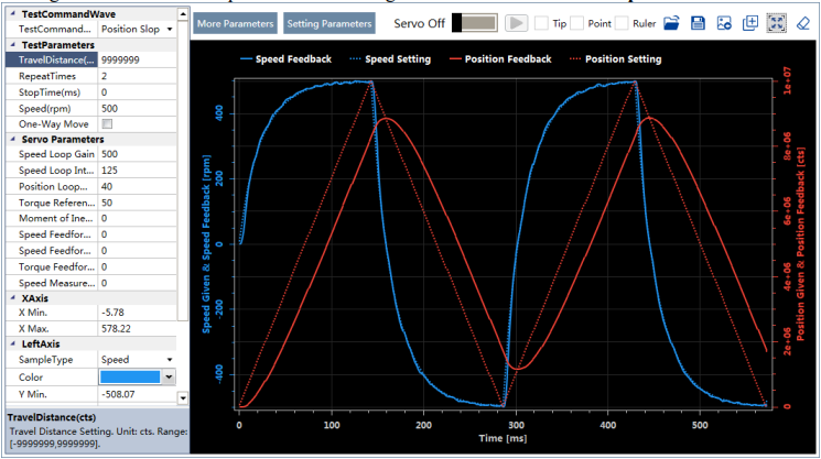
By using the Manual-Tuning Tool, you will set the Servo gain parameters again and again according to the waveform graphics of the data (Speed Feedback, Speed Setting, Position Feedback and Position Setting), as far as the performance of the servo meets the requirements.
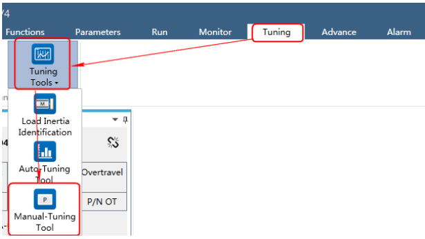
Step 1 Select Tuning → Tuning Tools → Manual-Tuning Tool in the Menu Bar of the ESView V4 main windows.
Step 2 The Manual-Tuning Tool window will be displayed in Function Display Area.
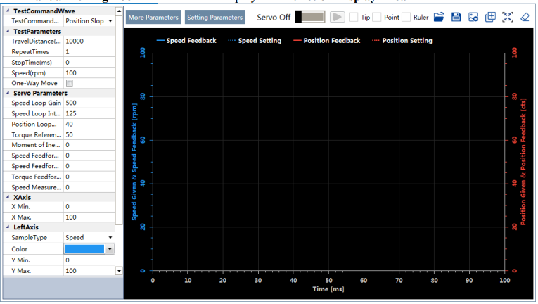
Step 3 Set the necessary parameters of the Test Command.
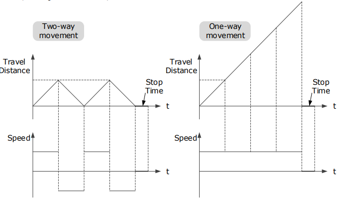
Choose Test Command Wave as Position Slope, the Drive will operate in position control method, and the trajectory of the Motor in Two-way movement and One-way movement is shown in the figure below. (Set Repeat Times as 2)
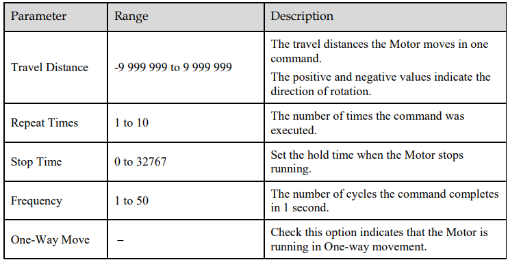
The relevant parameters in the Position Slope are shown in the table below.
Sinusoidal of position
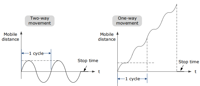
When "Test instruction waveform" is set to "position sine", the driver will run in position control mode, and the position instruction generated internally makes the motor move in non-unidirectional motion and the track of unidirectional motion as shown in Figure 8-14 (" Repetition times "is set to 2).
The relevant parameters in the Position Stepwise are shown in the table below.
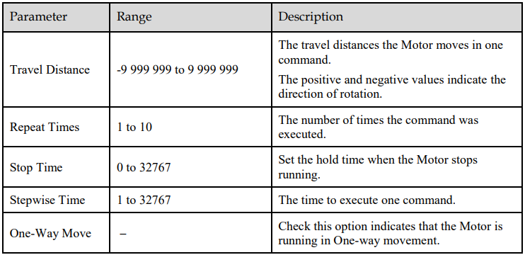
Queue a position steps
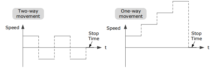
When "Test instruction waveform" is set to "position step", the driver will run in position control mode, and the position instructions internally generated make the motor move in non-unidirectional and unidirectional time sequence as shown in Figure 8-15 (assuming "repetition times" is set to 2)
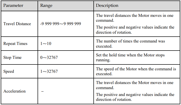
Linear velocity trapezoid
When "Test Instruction Waveform" is set to "speed trapezoid", the driver will run in position control mode, and the position instruction generated internally makes the motor in non-unidirectional motion and unidirectional motion speed waveform as shown in Figure 8-15 (" Repetition times "is set to 2).
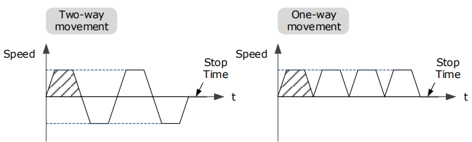
Anyway, you risk losing your set speed by setting the "travel distance" too small.
The relevant parameters in the Speed Trapezoid are shown in the table below
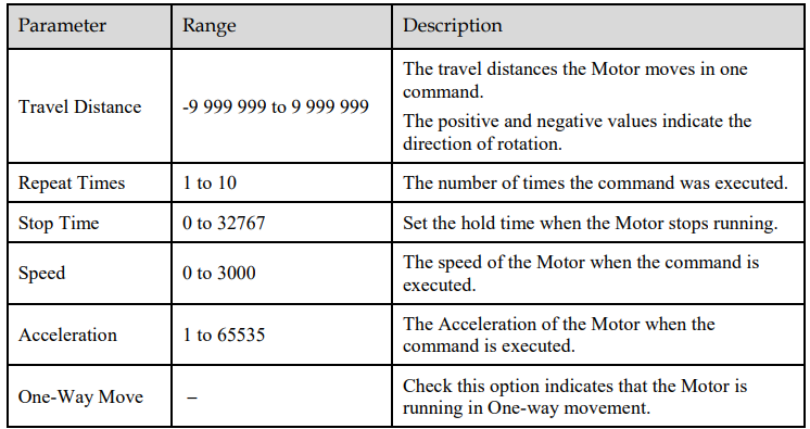
Step 4 Set the necessary parameters for the data collected.
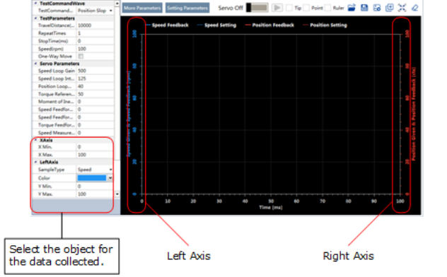
X Axis: Indicates Times.
Left Axis: Select Sample Type as Speed or Position.
This selection will affect the Sample Type of the Right Axis.
Right Axis: Select Sample Type as None, Speed, Position, or Offset.
The setting Offset indicates the deviation of the sample type (speed or position) selected by the left axis.
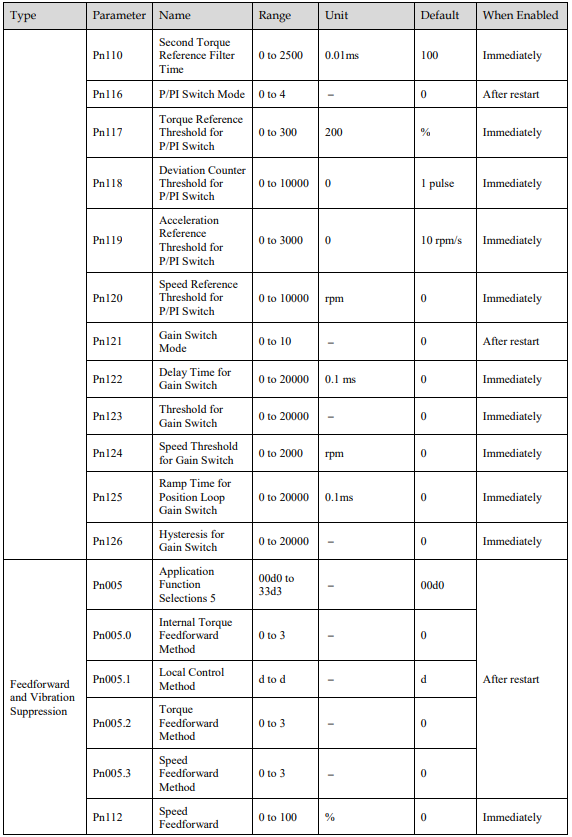
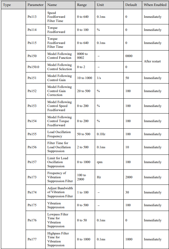
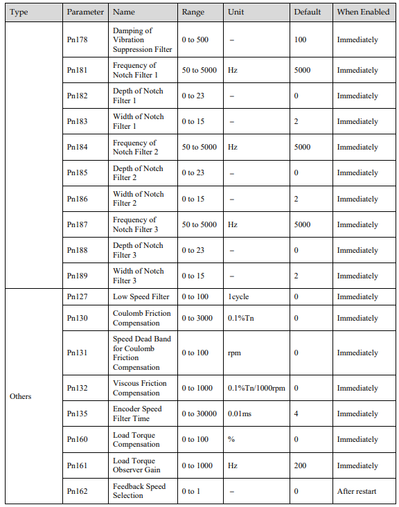
Step 5 Set the necessary parameters for the Servo gain.
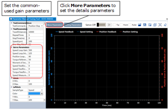
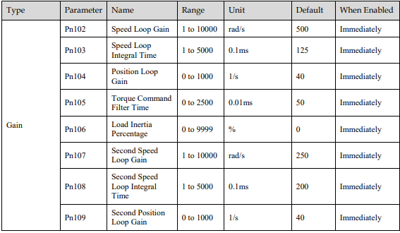
The parameters that may be used are shown in Table 8-3.
Table 8-3 The parameters that may be used
Step 6 Click Servo Off / Servo On for supplying power to the Motor.

Step 7 Click  to start using Manual-Tuning Tool

Step 8 When the Manual-Tuning Tool function has been completed, the waveform graphics of the data result is displayed in the window.
The figure below is an example of data collecting results with the Position Slope command.
Step 9 Repeat setting the parameters and perform the data collecting until result meets the requirements.
Step 10 Click Setting Parameters after confirming that the results have reached the desired performance, and the parameters will be written into the Drive.

----End