10. Fully-Closed Loop Control
10.1 Overview
With a fully-closed system, an externally installed encoder is used to detect the position of the controlled machine and the machine’s position information is fed back to the Drive. High-precision positioning is possible because the actual machine position is fed back directly. With a fully-closed system, looseness or twisting of mechanical parts may cause vibration or oscillation, resulting in unstable positioning.
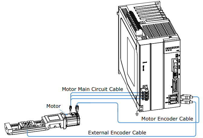
The following figure shows an example of the system configuration.
10.2 Commissioning Procedure
First, confirm that the Drive operates correctly with semi-closed loop control, and then confirm that it operates correctly with fully-closed loop control.
The commissioning procedure for the Drive for fully-closed loop control is given below.
Step 1 Complete the wiring and connection of the Drive and Motor, and connect to the machine.
Refers to the section 8.4 Motor Operation with a Load.
Step 2 Set Pn210.0=0 (Do not use an external encoder) to specify semi-closed loop control.
Step 3 With the JOG operation, move the movable part on the machine side to an appropriate position, and then confirm the Motor's motion in forward rotation and reverse rotation.
For details on JOG operation, refers to the section 8.3.3 JOG Operation.
Step 4 Set Pn210.0=1 (Use an external encoder for the fully-closed loop control) to specify fully-closed loop control.
Step 5 Using the JOG operation again to confirm the Motor's motion in forward rotation and reverse rotation.
Step 6 Resolve the following alarms and reset the system.
If alarms A90 (Phase A Disconnected), A91 (Phase B Disconnected), A92 (Phase C Disconnected) alarms occur, check the wiring of the external encoder.
If an alarm A93 (Encoder Communications Error) occurs, contact ESTUN or the Authorized Distributor.
If an alarm A94 (Position Deviation Overflow) occurs, check the settings of Pn210, Pn212, Pn213 and Pn214. Also, you may check the wiring of the external encoder, and check if the mechanical connection structure is loose, slippery or has a large gap.
Step 7 Check the settings of parameters Pn210.3, Pn212, and Pn213.
You may set Pn210.3 to change the count direction of the external encoder.
According to your application, set Pn212 to change the size of the external encoder resolution.
Set Pn213 to change Position Deviation Threshold between Encoder and External Encoder.
Step 8 Try to use the PJOG operation to confirm the Motor’s motion.
For details on PJOG operation, refers to the section 8.5 Program Jogging.
Step 9 Refers to the Step 6, to resolve possible alarms until the alarm no longer occurs.
Step 10 Confirm that the servo can operate normally in PJOG operation, indicating that the Servo can operate in fully-closed loop control.
10.3 Parameter Settings
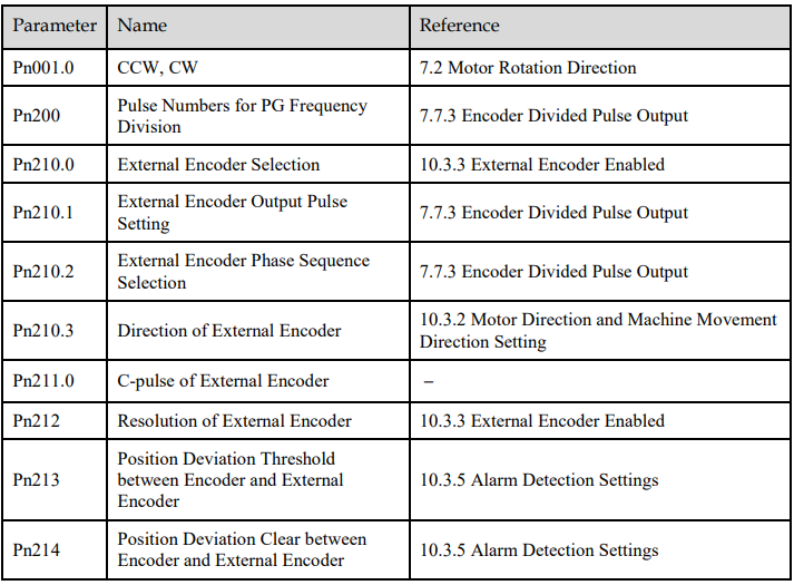
To properly perform fully-closed loop control, you may set the following parameters.
10.3.1 Control Block Diagram
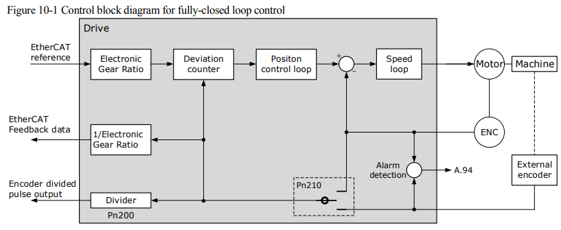
The control block diagram for fully-closed loop control is as shown in Figure 10-1.
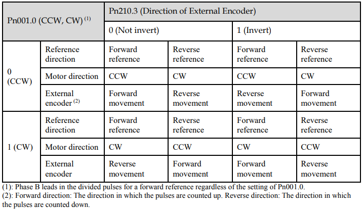
10.3.2 Motor Direction and Machine Movement Direction Setting
You must set the Motor direction and the machine movement direction. To perform fully-closed loop control, you must set the Motor rotation direction with both Pn001.0 (CCW, CW) and Pn210.3 (Direction of External Encoder).
10.3.3 External Encoder Enabled
Set Pn210.0=1 or 2 to enable the external encoder:
Set Pn210.0 to 1, representing that the external encoder is enabled for the fully-closed loop control.
Set Pn210.0 to 2, representing that the external encoder is enabled for the counting only.
In addition, set the parameter Pn212 (Resolution of External Encoder) to specify the resolution of the external encoder, indicating the numbers of AB quadrature pulse edges emitted by the external encoder after one rotation of the Motor (one quadrature pulse has four edges, that is, the pulse numbers × 4).

10.3.4 Encoder Divided Pulse Output for External Encoder
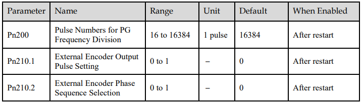
To use the encoder divided pulse output, you shall set Pn200 (Pulse Numbers for PG Frequency Division) and parameter Pn210.1 (External Encoder Output Pulse Setting).
For details on encoder divided pulse output, refers to the section 7.7.3 Encoder Divided Pulse Outpu.
If the external encoder is used for the divided pulse output (Pn210.1=1), you can also set Pn210.2 to select whether to invert the output signals.
10.3.5 Alarm Detection Settings
This setting is used to detect the difference between the feedback position of the Motor encoder and the feedback load position of the external encoder for fully-closed loop control.
If the detected difference exceeds the setting, an A94 alarm (Position Deviation Overflow) will be output.
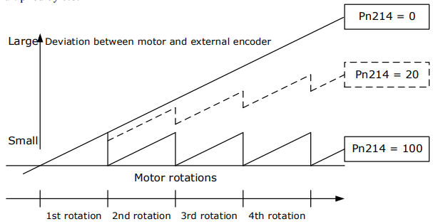
In addition, you shall set the coefficient of the deviation between the Motor and the external encoder per Motor rotation (Pn214). This setting can be used to prevent the Motor from running out of control due to damage to the external encoder or to detect belt slippage.
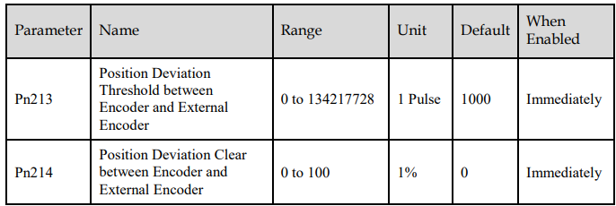
If Pn214 is set to 0, the external encoder value will be read as it is.
If you set Pn214 to 20, the second rotation will start with the deviation for the first Motor rotation multiplied by 0.8.