
2. Installation
2.1 Installation Precautions
Installation Near Sources of Heat
Implement measures to prevent temperature increases caused by radiant or convection heat from heat sources so that the ambient temperature of the Drive meets the ambient conditions.
Installation Near Sources of Vibration
Install a vibration absorber on the installation surface of the Drive so that the Drive will not be subjected to vibration.
Other Precautions
Never install the Drive in a location subject to high temperatures, high humidity, water drops, cutting oil, excessive dust, excessive dirt, excessive iron powder, corrosive gasses, or radioactivity.
2.2 Mounting Types and Orientation
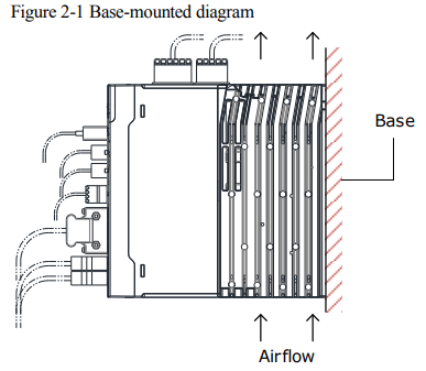
The Drives are based mounted. Mount the Drive vertically, as is shown in Figure 2-1. Mount the Drives so that the Panel Operator is facing toward the operator. And, prepare two or three mounting holes for the Drive and mount it securely in the mounting holes (The number of mounting holes depends on the capacity of the Drive).
2.3 Mounting Hole Dimensions
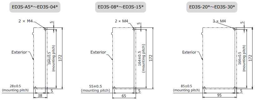
Use two or three mounting holes to securely mount the Drive to the mounting surface.
To mount the Drive, you will need to prepare a screwdriver that is longer than the depth of the Drive.
2.4 Mounting Interval
Installing One Drive in a Control Cabinet
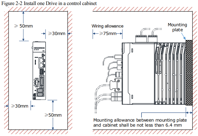
Provide enough space around the Drive when installing one Drive in a control cabinet, as is shown in Figure 2-2.
Installing More than One Drive in a Control Cabinet
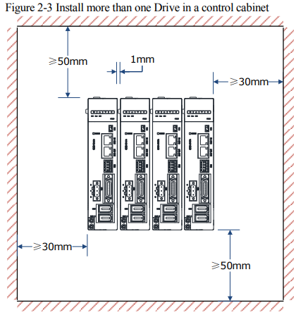
Provide enough space around the Drive when installing more than one Drive in a control cabinet, as is shown in Figure 2-3.

2.5 EMC Installation Conditions
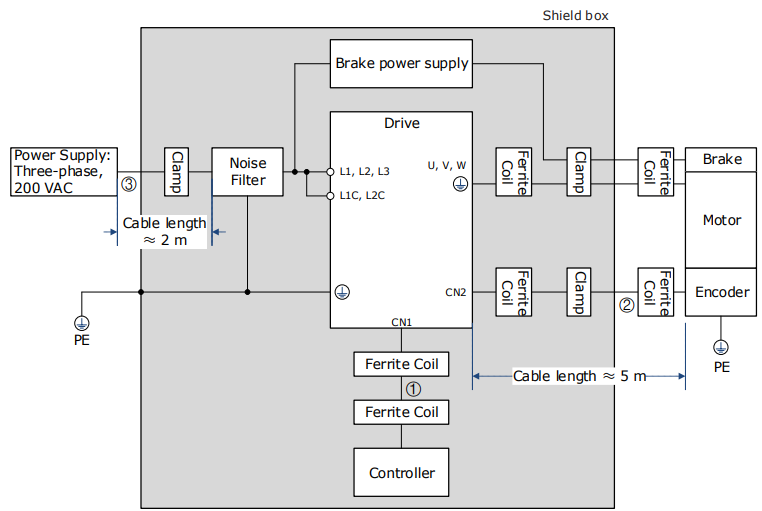
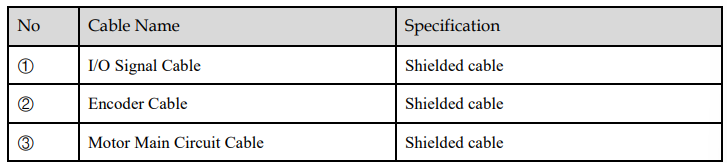
This section gives the installation conditions that were used for EMC certification testing.
2.5.1 EMC Directives
The EMC installation conditions that are given here are the conditions that were used to pass testing criteria at ESTUN. The EMC level may change under other conditions, such as the actual installation structure and wiring conditions. These ESTUN products are designed to be built into equipment. Therefore, you must implement EMC measures and confirm compliance for the final equipment.
2.5.2 Ferrite Coil Mounting
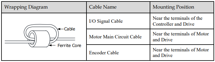
Ferrite Coil Attached
Wrap the cable around the ferrite coil for 2 turns. The Ferrite Coil mounting positions of each cable is shown in the following table.
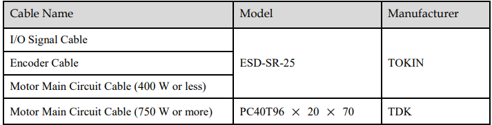
Recommended Model of Ferrite Core
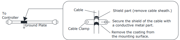
Cable Fixed
Secure the shield of the cable with a conductive metal part, and fix it to the ground plate.
Shield Box
Use a shield box with the closed metal housing to shield electromagnetic interference from the Drive. The shield box must have a structure that allows the body, door, cooling device, etc. to be grounded, and the opening of the shielding box shall be as small as possible.
