5. EtherCAT Communications
5.1 Introduction
5.1.1 Protocol Overview
EtherCAT is an open network based on Ethernet to achieve real time control. It could support high speed and synchronized control. By using efficient network topology, the network structure with too many concentrator and complicated connections are avoided. It is very suitable to use this protocol in motion control and other factory automation applications.
EtherCAT is registered trademark and patented technology, licensed by Beckhoff Automation GmbH, Germany.
EtherCAT technology breaks the limits of normal internet solution. Through this technology, we don’t need to receive Ethernet data, decode the data, and then copy the process data to different devices. EtherCAT slave device could read the data marked with this device’s address information when the frame passes this device. As the same, some data will be written into the frame when it passes the device. In this way, data reading and data writing could be done within several nanoseconds.
EtherCAT uses standard Ethernet technology and support almost kinds of topologies, including the line type, tree type, star type and so on. Its physical layer could be 100 BASE-TXI twisted-pair wire, 100BASE-FX fiber or LVDS (low voltage differential signaling). It could also be done through switch or media converters or in order to achieve the combination of different Ethernet structure.
Relying on the ASICs for EtherCAT in the slave and DMA technology that reads network interface data, the processing of the protocol is done in the hardware. EtherCAT system could update the information for 1000 I/O within 30 µs. It could exchange a frame as big as 1486 bytes within 300 µs. This is almost like 12000 digital output or input. Controlling one servo with 100 8-byte I/O data only takes 100 µs. Within this period, the system could update the actual positions and status presented by command value and control data. Distributed clock technology could make the cyclic synchronous error lower than 1 µs.
5.1.2 Specification
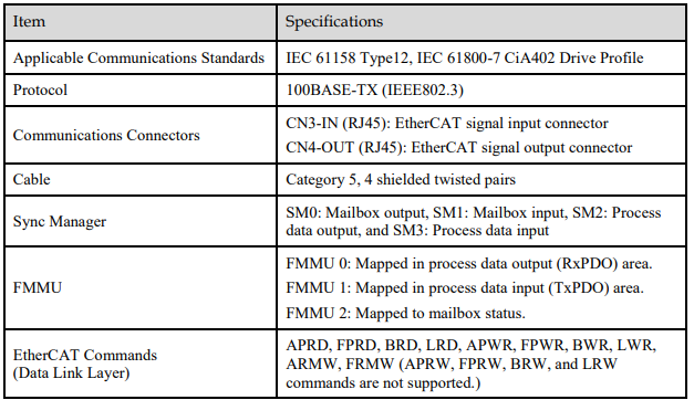
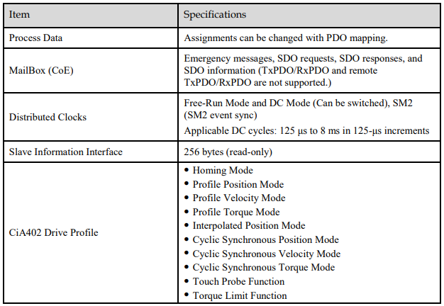
The specifications for EtherCAT communication are as follows.
5.2 Relevant Settings
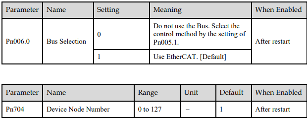
If the EtherCAT network cannot communicate, check the settings of the parameters Pn006 and Pn704.
5.3 EtherCAT Basis
5.3.1 CANopen over EtherCAT Reference Model
CANopen over EtherCAT (CoE) reference model is as shown in Figure 5-1.
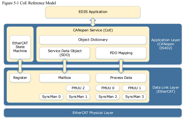
The coe reference model mainly includes two parts: the Data Link Layer and the Application Layer. The Data Link Layer is mainly responsible for the EtherCAT communication protocol, and the Application Layer embeds the CANopen drive profile (DS402) communication protocol. The Object Dictionary in the Application Layer contains parameters, application data, and PDO mapping information.
The Process Data Object (PDO) consists of objects in the object dictionary that can be mapped to the PDO. The contents of the process data are defined by the PDO mapping. Process data communication cyclically reads writes the PDO.
Mailbox communication (SDO) uses asynchronous message communications where all object in the object dictionary can be read and written.
5.3.2 EtherCAT Slave Information
You can use EtherCAT slave information files (XML format) to configure the EtherCAT master. The XML file contains the standard EtherCAT communications settings for the Drive. The following file is provided for the Drive:
ESTUN_ED31_V***.xml
NOTE: The asterisks (***) indicate the version number
5.3.3 EtherCAT State Machine
The EtherCAT state machine is used to manage the communications states between the master and slave applications when EtherCAT communications are started and during operation, as shown in Figure 5-2. Normally, the state changes for requests from the master
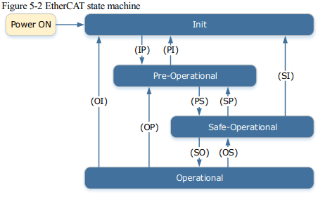
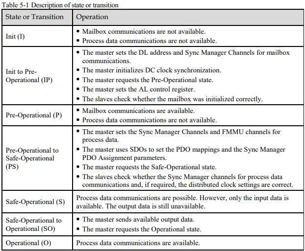
Table 5-1 lists the state transition and initialization process.
5.3.4 Process Data Object (PDO)
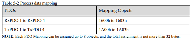
The ED3S provides 4 RxPDOs and 4 TxPDOs, all of which support dynamic mapping. The mapping objects are shown in Table 5-2.
PDO Assignment
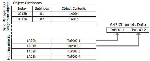
The Sync Manager Channels SM2 is responsible for receiving the data from RxPDO, and Sync Manager Channels SM3 is responsible for transmitting the data in TxPDO.
The Sync Manager PDO assignment objects (1C12h and 1C13h) establish the relationship between these PDOs and the Sync Managers. The following figure shows an example that how to set the relationship between SM3 and TxPDO through object 1C13h.
PDO Mapping
POD mappings are definitions of the applications objects that are sent with PDOs (RxPDOs and
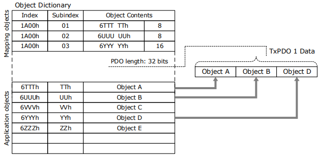
TxPDOs). The PDO mapping tables are in indexes 1600h to 1603h and 1610h to 1613h for the RxPDOs (RxPDO 1 to RxPDO 4) and indexes 1A00h to 1A03h and 1A10h to 1A13h for the TxPDOs (TxPDO 1 to TxPDO 4) in the object dictionary.
Each PDO mapping object can be added up to 10 objects, and the total assignment is not more than 32 bytes. The following figure shows a mapping example of TxPDO 1. The mapping object is 1A00h.
Taking SM2 channel and RxPDO 1 as an example, the steps of PDO mapping are as follows:
1. Disable the assignment between the SM2 and RxPDO 1:
Set subindex 00h in object 1C12h to 0.
2. Disable the assignments of RxPDO 1:
Set subindex 00h in object 1600h to 0.
3. Set all of the mapping entries (index and subindex) for the RxPDO 1 mapping objects:
Write the mapping entity index and subindex values into the corresponding subindex of 1600h.
4. Set number of mapping entries for the RxPDO 1 mapping objects:
Write the number of mapping entries into the subindex 00h of 1600h.
5. Set the assignments between the SM2 and RxPDO 1:
Set subindex 01h in object 1C12h to 0x1600.
6. Enable the assignments between the Sync Manager and RxPDO 1:
Set subindex 00h in object 1C12h to 1.

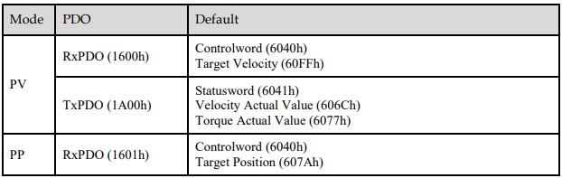
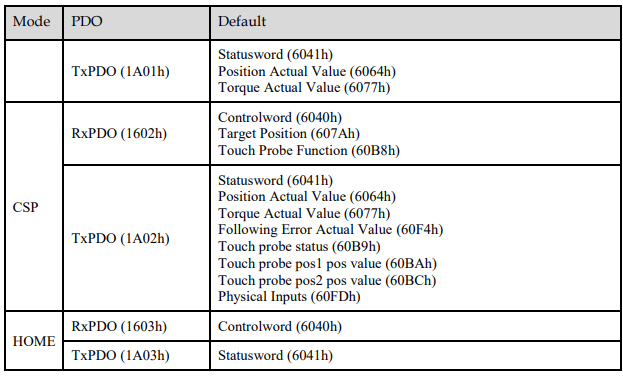
Default PDO Mappings
The following table shows the default PDO mappings for the Drive. These initial settings are also defined in the EtherCAT slave information file (XML format).
5.3.5 Service Data Object (SDO)
SDO is used to transfer non-cyclic data, such as communication parameter configuration, and Servo running parameter configuration. The CoE service type includes Emergency Message, SDO request and SDO response.
5.3.6 Emergency Message
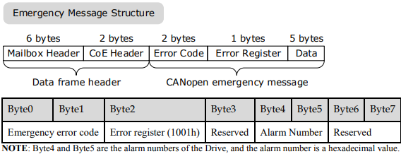
When an alarm occurs in the Drive, the CoE service can trigger an emergency message to inform the user of the error code.
An emergency message consists of eight bytes of data as shown in the following description
5.3.7 Distributed Clock (DC)
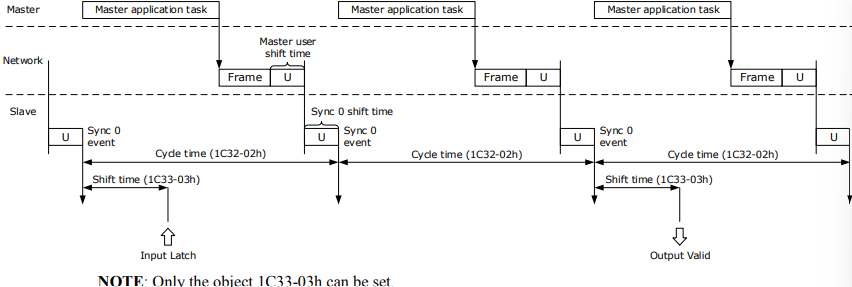
The synchronization of EtherCAT communications is based on a mechanism called a distributed clock. With the distributed clock, all devices are synchronized with each other by sharing the same reference clock. The slave devices synchronize the internal applications to the Sync0 events that are generated according to the reference clock.
You can use the following synchronization modes with EtherCAT (CoE). You can change the synchronization mode in the Sync Control registers (ESC registers 0x980 and 0x981).
Free-Run (ESC register0x981: 0x980 = 0x0000)
In Free-Run mode, the local cycle is independent from the communications cycle and master cycle.
DC Mode (ESC register0x981: 0x980 = 0x0300)
In this mode, the Drive is synchronized with the host controller (master) on the Sync0 event.
The following figure gives a timing chart for DC synchronization.
5.4 Communication Indication
5.4.1 Indicator Lamps on Panel Operator
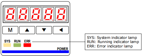
There are 3 indicator lamps on the panel Operator of the Drive to indicate the communication status of EtherCAT: SYS, RUN and ERR.
SYS Indicator
The SYS indicator shows the system status of EtherCAT communications.
RUN Indicator
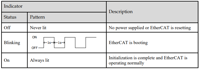
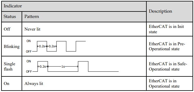
The RUN indicator shows the status of EtherCAT communications.
ERR Indicator
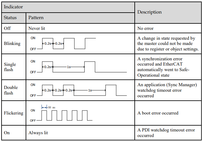
The ERR indicator shows the error status of EtherCAT communications.
5.4.2 Indicator Lamps on RJ45
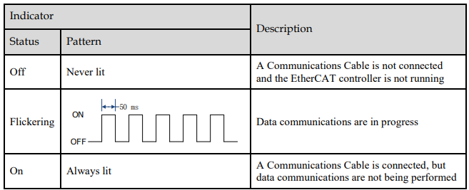
The Link/Activity indicators show whether Communications Cables are connected to the CN3-IN and CN3-OUT connectors and whether communications are active.