8. Device Settings
You are recommended to complete device settings in following order: Device Connection → Image Settings → Algorithm Settings → I/O Control Settings → Data Processing → Communication Settings → Configuration Management.

● Device Connection: It tells you how to connect the device to the client software. And you can configure and operate the device remotely via the client software only when you have connected the device to the client software. Refer to Connect Device to Client Software for details.
● Image Settings: It tells you how to set image related parameters of the device via client software. Refer to Image Quality Settings for details.
● Algorithm Settings: It tells you how to set the types of barcode to be read, the 1D code algorithm, the 2D code algorithm, etc. Refer to Code Algorithm Settings for details.
● I/O Control Settings: It tells you how to set the parameters related to the control of input and output signals of device. Refer to Signal Input Settings and Signal Output Settings for details.
● Data Processing: It tells you how to set filter rules for reading barcodes and other data processing related parameters. Refer to Code Reading Result Settings for details.
● Communication Settings: It tells you how to select different communication protocols, and set their corresponding parameters. Refer to Communication Settings for details.
● Configuration Management: It tells you how to set and manage the user parameters, restart device, etc. Refer to User Set Customization for details.
8.1 Image Quality Settings
This section introduces how to set image related parameters of the device via client software.

8.1.1 Set Image
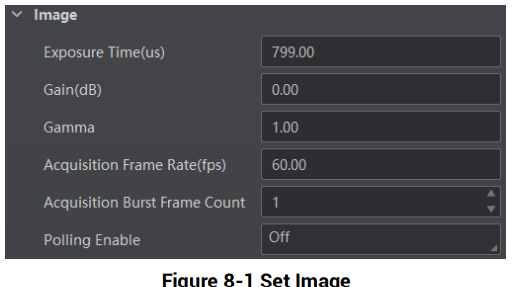
You can set different image parameters like exposure time, gain, Gamma, acquisition frame rate, acquisition burst frame count in image parameters interface.

Exposure Time
You can increase exposure time to improve image brightness.

Gain
You can increase gain to improve image brightness.

Gamma
Gamma allows you to adjust the image contrast. It is recommended to reduce Gamma to increase brightness in dark background.
Acquisition Frame Rate
Acquisition frame rate refers to the image number that is acquired by the device per second.
Acquisition Burst Frame Count
Acquisition burst frame count refers to the outputted image number when the device is triggered once.
Polling Enable
It enables the polling function, you can select off, single or multiple mode.

8.1.2 Set Polling
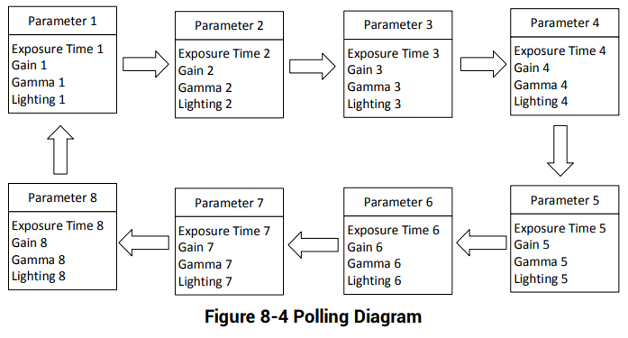
The polling function allows the device to acquire images based on the parameters you set, including exposure time, gain, Gamma, and light source. Currently, 2 types of polling modes are available, including single mode and multiple mode.
Single Mode
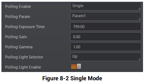
Steps
1. Go to Image Settings → Image → Polling Enable, and select Single as Polling Enable.
2. Select one parameter (e.g. Param1) from Polling Param.
3. Set Polling Exposure Time, Polling Gain, and Polling Gamma according to actual demands
4. Select Polling Light Selector according to actual demands, and enable Polling Light Enable.
Multiple Mode
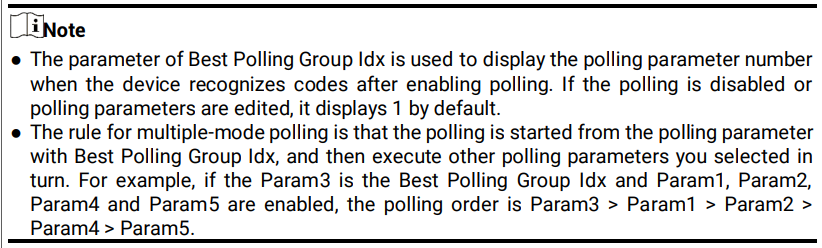
Steps
1. Go to Image Settings → Image → Polling Enable, and select Multiple as Polling Enable.
2. Set Polling Time and Polling Period according to actual demands.
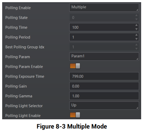
3. Select 2 to 8 sets of parameters (e.g. Param1 and Param2) from Polling Param, and enable Polling Param Enable to let them take effect.
4. Set Polling Exposure Time, Polling Gain, and Polling Gamma for the Polling Param you selected.
5. Select Polling Light Selector according to actual demands, and enable Polling Light Enable.
6. Repeat step 3 to step 5 to set other parameters from Polling Param.
8.1.3 Set Light Source
You can select different light types, and set their related parameters in the light interface.

You can select different light sources in Light Type.
Own Lighting
It refers to use the device's embedded light source to light during code reading.
External Lighting
It refers to the device controls the external light source by triggering output signal during code reading.
Non-Lighting
It refers to the device turns off light source during code reading.

Set Own Lighting
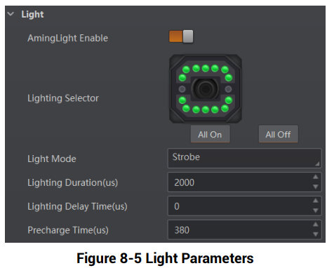
If you select Own Lighting as Light Type, you can set the following parameters.
Aiming Light Enable
You can enable Aiming Light Enable to enable the device’s aiming light.

Lighting Selector
You can click lamps on the light source illustration to turn on or turn off lamps on different directions.

Light Mode
It has 2 light modes, including Strobe and Long. Strobe means the light flashes at a specific interval during code reading, and Long means the light is solid during code reading.
Lighting Duration
It sets the lighting duration and the unit is μs.
Lighting Delay Time

It determines the delay time for lighting after exposure and the unit is μs.
Precharge Time
It determines how earlier the light source starts lighting before exposure and the unit is μs.

Set External Lighting
If you select External Lighting as Light Type, you can set the following parameters.
Line Out Duration
The lighting duration of the external light source and the unit is μs.
Line Out Delay Time
It sets the delay time for lighting after device outputs event source, and the unit is μs.
Line Out Ahead Time
It sets how earlier the external light starts lighting before the device outputs event source information, and the unit is μs.
8.1.4 Set Lens Focus
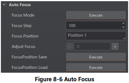
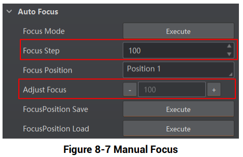
The device supports setting lens focus via the client software. 2 ways are available to set lens focus, including auto focus and manual focus.

Auto Focus
Steps
1. Click  in the live view window.
2. Go to Image Settings → Auto Focus, and click Execute in Focus Mode.
The device starts to adjust focus automatically.
3. Select the position parameter from Focus Position, and click Execute in Focus Position Save to save the focus position.
4. (Optional) Select the position parameter from Focus Position, and click Execute in Focus Position Load to load saved focus position.
Manual Focus
1. Go to Image Settings → Auto Focus, and set Focus Step according to actual demands.
2. Click or in Adjust Focus to adjust focus.
3. Select the position parameter from Focus Position, and click Execute in Focus Position Save to save the focus position.
4. (Optional) Select the position parameter from Focus Position, and click Execute in Focus Position Load to load saved focus position.
8.1.5 Set Self-Adaptive Adjustment

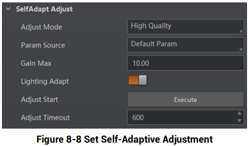
The function of self-adaptive adjustment can automatically adjust exposure, gain, Gamma and other parameters to have a better code reading effect.
Steps
1. Right click the device in Device Connection, and click Feature Tree.
2. Go to Self Adapt Adjust, and select Adjust Mode.
● High Quality: In this mode, the client software will adjust exposure in priority with small gain and noise. The image quality is high, and this mode is applicable to the scenario for low speed conveyer belt.
● High Speed: In this mode, the client software will adjust gain in priority with small exposure and large gain. The image quality is less high, and this mode is applicable to the scenario for high speed conveyer belt.
3. Select Param Source according to actual demands.
● Default Param: It adjusts the default parameters.
● Polling Param: It adjusts parameters configured in polling.
4. (Optional) Enable or disable Lighting Adapt during self-adaptive adjustment. If it is enabled, the client software will select the best one from all lighting options during the selfadaptive adjustment. If it is disabled, the client software will keep the lighting status before the self-adaptive adjustment.
5. (Optional) Set Gain Max or Exposure Max according to actual demands.
● Gain Max: It is enabled in high quality mode, and it sets the max. gain during the selfadaptive adjustment.
● Exposure Max: It is enabled in high speed mode, and it sets the max. exposure during the self-adaptive adjustment.
6. (Optional) You can set Adjust Timeout to set the duration of the self-adaptive adjustment, and the adjustment will stop if the duration is exceeded. The unit of Adjust Timeout is second.
7. Click Execute in Adjust Start. The device will automatically acquire images and perform self-adaptive adjustment, and stop acquisition after adjustment is completed.

8.1.6 Set Mirror X
The device supports the mirror X function. If this function is enabled, the image will be reversed in a horizontal way.
Go to Image Settings, click All Features, and you can see the Mirror X.

8.1.7 Set Test Pattern
Test pattern helps troubleshooting image problems and images in the test pattern are only for test. When exceptions occur in images acquired by the device in real time, you can check if images in the test pattern have similar problems to determine the cause of an exception.

Go to Image Settings, click All Features, find Test Pattern in Other Features, and set Test Pattern according to actual demands.
8.2 Code Algorithm Settings
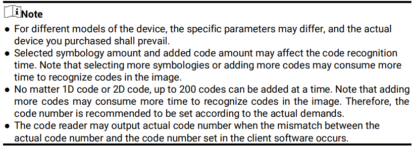
The code reader supports reading multiple types of 1D code and 2D code, and you can add and set code parameters via the client software.
8.2.1 Add Code
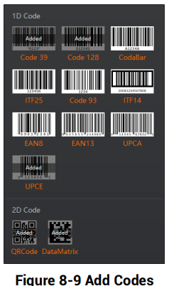
Adding code before you set code parameters via the client software. In Algorithm Settings, you can add different types of codes according to actual demands.
In Algorithm Settings, click Add Barcode, select the types of codes to be read, and set the 1D Code Number and 2D Code Number according to actual demands.
8.2.2 Set Code Reading ROI
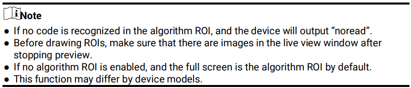
Algorithm ROI (Region of Interest) allows the device to execute algorithms and read codes on the specific area you selected, and thus improving code reading efficiency.
Currently, up to 4 ROIs can be configured, and the device outputs codes according to the number of ROI (e.g. Region 1, Region 2, and Region 3) in turn. The client software supports drawing single group of ROI, drawing ROI in batch, and drawing ROI via chessboard.
Draw Single Group of ROI
Steps
1. Go to Algorithm Settings, click All Features, and find Algorithm ROI.
2. Click Draw to draw ROI in the live view window.
3. (Optional) Repeat the above step to draw multiple ROIs according to actual demands

4. (Optional) Set other ROI parameters according to actual demands.
● ROI Index: It indicates different ROIs and ranges from 0 to 149 which corresponds 1 to 150 ROIs.
● Draw ROI Width: It refers to the width in algorithm ROI.
● Draw ROI Height: It refers to the height in algorithm ROI.
● Draw ROI Offset X: It refers to the X coordinate of the upper left corner in algorithm ROI.
● Draw ROI Offset Y: It refers to the Y coordinate of the upper left corner in algorithm ROI.

5. (Optional) Click Execute in Restore Max. Algorithm ROI to restore the ROI to the full screen.
6. (Optional) Click Execute in Clear All ROI to delete all ROIs.
7. (Optional) Enable ROI Link IO Enable in Algorithm Control, and there will be prompts by the output device when codes are not read in any ROI.

Draw ROI in Batch
Steps
1. Go to Algorithm Settings, click All Features, and find Algorithm ROI.
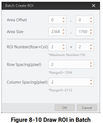
2. Click Batch to set parameters according to actual demands.
● Area Offset: It sets the pixel quantity from the starting point when the ROI is in horizontal and vertical direction from the full resolution.
● Area Size: It sets the pixel quantity in the horizontal and vertical direction of the ROI.
● ROI Number: It sets the row and column quantity.
● Row Spacing: It sets the interval between rows.
● Column Spacing: It sets the interval between columns.
3. Click OK after settings.
4. Repeat other optional steps mentioned in drawing single group of ROI according to actual demands.
5. (Optional) Enable ROI Link IO Enable in Algorithm Control, and there will be prompts by the output device when codes are not read in any ROI.

Draw ROI via Chessboard
Steps
1. Go to Algorithm Settings, click All Features, and find Algorithm ROI.
2. Click Execute in Chessboard ROI, set parameters according to actual demands, and click OK after setting.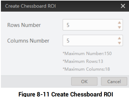
3. Click after creating ROI, and the red frame becomes green as shown below.
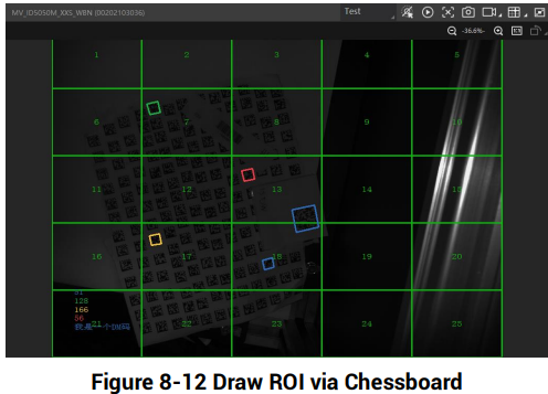
4. (Optional) Click  to restore the ROI to the full screen, and click
 to clean all configured ROIs.
5. Repeat other optional steps mentioned in drawing single group of ROI according to actual demands.
6. (Optional) Enable ROI Link IO Enable in Algorithm Control, and there will be prompts by the output device when codes are not read in any ROI.

8.2.3 Set 1D Algorithm Parameter
Click All Features on the upper-right to display all algorithm parameters. In the Algorithm Parameter page, select 1DCode as Arithmetic Type, and then you can set its corresponding parameters.

Timeout Value
Timeout value refers to the maximum running time of algorithm, and its unit is ms. The code reader will stop parsing the images and return results if the time is exceeded the waiting time configured.
Code Color
It defines the readable code color. White Code On Black Wall means that the client software can recognize the white code with black background. Black Code On White Wall means that the client software can recognize the black code with white background.
Code 39 Check
Enable this parameter if Code 39 uses the parity bit.

ITF 25 Check
Enable this parameter if ITF 25 uses the parity bit.

Code Score Enable
If it is enabled, the device will evaluate code quality and display overall grade and code score in history record area of the client software. The higher the score, and the better the code quality.
Accurate Timeout Enable
If it is enabled, the accuracy of algorithm timeout will improve.
8.2.4 Set 2D Algorithm Parameter
Click All Features on the upper-right to display all algorithm parameters. In the Algorithm Parameter page, select 2D Code as Arithmetic Type, and then you can set its corresponding parameters.

Timeout Value
Timeout value refers to the maximum running time of algorithm, and its unit is ms. The code reader will stop parsing the images and return results if the time is exceeded the waiting time configured.
Algorithm Running Mode
It is used to be set the algorithm operating mode. It includes High Speed, High Performance, and Balance. High Speed focuses on recognition speed, and the algorithm can recognize the code rapidly, while High Performance refers to the algorithm can recognize the code that has distortion, spot or white gap, but its recognition speed is slow. Balance refers to the algorithm makes a balance between speed and performance.
2D Code Max. Size
It refers to the max. recognizable code width. The 2D code will not be recognized if its width exceeds the configured value.
Mirror Mode
It is useful when the recognized image is a mirror one, mirroring in X coordinate. 3 modes are available: Adaptive, Mirror, and Non Mirror.
Downsampling Level
It refers to the pixel sample size that the code reader takes. Increasing this parameter will improve the code reading efficiency at the expense of code recognition rate.

Code Color
It defines the readable code color. Adaptive means that the client software can recognize both the black code with white background, and the white code with black background. White Code On Black Wall means that the client software can recognize the white code with black background. Black Code On White Wall means that the client software can recognize the black code with white background.
Note
● For QR code, the code color is determined by the color of the concentric square on it. indicates that the code color is white, and indicates that the code color is black.
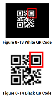
● For DM code, the code color is determined by the color of its "L" shaped sides. White "L" shaped sides indicate that the code color is white, and black "L" shaped sides indicate that the code color is black.
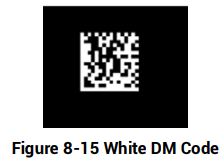
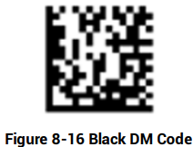
Discrete Flag
Continuous stands for the minimum units in the "L" shaped sides of the DM code are continuous, or the minimum units in the concentric square like or in the QR code are continuous. Usually the continuous code uses squares as the minimum units. Discrete stands for the minimum units in the "L" shaped sides of the DM code are discrete, or the minimum units in the concentric square like or in the QR code are discrete. Usually the discrete code uses dots as the minimum units. Adaptive stands for the device can recognize both continuous code and the discrete code.
QR Distortion Correction
If the QR code or DM code is distorted, you can enable this parameter to improve code recognition rate.

Advance Param
This parameter is applicable to some special codes, and it is recommended to use the default value.
DM Code Shape
It defines the recognizable code shape. Square stands for square mode: If the 2D code is square shaped, it can be recognized by the device. Rectangle stands for rectangle mode: If the 2D code is rectangle shaped, it can be recognized by the device. Adaptive stands for compatible mode: The device can recognize 2D codes of both the abovementioned two shapes.
DM Code Type
It includes All, ECC140, and ECC200.
2D Code Quality Enable
Refer to section Set 2D Code Quality Evaluation for details.
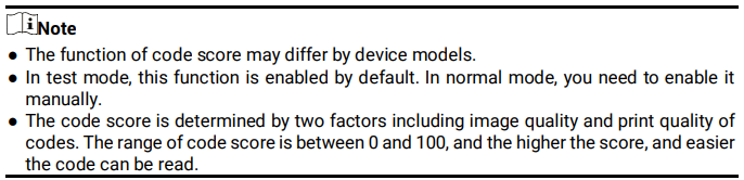
Code Score Enable
If it is enabled, the device will evaluate code quality and display overall grade and code score in history record area of the client software. The higher the score, and the better the code quality.
Accurate Timeout Enable
If it is enabled, the accuracy of algorithm timeout will improve.
8.2.5 Set 2D Code Quality Evaluation
After 2D Code Quality Enable, you can set specific parameters according to actual demands.

Steps
1. Set Sym Proc Type according to actual demands, and the default type is Type 1. Type 1 has a strong capacity to locate codes.
2. Set Iso Edition, including Iso15415 and Iso29158
● Iso15415 is applicable to the quality evaluation for label 2-dimensional codes.
● Iso29158 is applicable to the quality evaluation for DPM format 2-dimensional codes.
3. Set Verify Edition, including standard mode and HIK mode.
● Standard mode is a standard quality evaluation mode.
● HIK mode is a professional quality evaluation mode.
4. Set Standard Aperture and Magnification.
● Standard aperture refers to a standard aperture, and its default value is 400.
● Magnification is 150 by default.

5. Click  to start acquisition, and the client software will display the overall code quality in the history area.
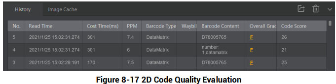

6. (Optional) Click specific grade in the overall grade list to view different quantity evaluation items.
8.2.6 Set Code Score
After enabling code score function, the client software can output specific score for codes it has read.
Steps
1. Right click the device in Device Connection, and click Feature Tree.
2. Go to Algorithm Control, and enable Code Score Enable.
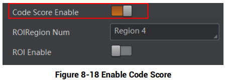
3. Click  to start acquisition, and the client software will display specific code score in the history area.
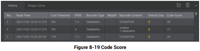
4. (Optional) Go to Image Settings, and adjust parameters like exposure time, gain, Gamma, light source, etc. if the code score is low.

8.3 Signal Input Settings
In the signal input module, you can set the trigger related parameters. You can enable trigger mode to let the acquisition of image data occur only when the trigger source is generated.
8.3.1 Set Trigger Mode
The device has 2 types of trigger mode: Internal trigger mode and external trigger mode.
Internal Trigger Mode
In this mode, the device acquires images via its internal signals.
External Trigger Mode
In this mode, the device acquires images via external signals like software signal and hardware signal. The trigger source of external trigger mode includes software, physical lines, counter, TCP, UDP, and serial.
8.3.2 Enable Internal Trigger Mode
In the internal trigger mode, the device acquires images via its internal signals. You have 2 methods to enable the internal trigger mode:
● Click I/O Control Settings → Input → Trigger Mode, and select Off as Trigger Mode.
● In the live view page, click  to enable the internal trigger mode.
8.3.3 Enable External Trigger Mode
In the external trigger mode, the device acquires images via external signals like software signal and hardware signal. You have 2 methods to enable the external trigger mode:
● Click I/O Control Settings → Input → Trigger Mode, and select On as Trigger Mode.
● In the live view page, click  to enable the external trigger mode.
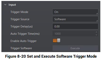
Set and Execute Software Trigger Mode
In software trigger, the software sends trigger signal to the device via I/O interface to acquire images.
Steps
1. Click I/O Control Settings → Input → Trigger Mode.
2. Select On as Trigger Mode.
3. Select Software as Trigger Source.
4. Click Execute in Trigger Source to send trigger commands.
You can also enter Auto Trigger Time, and then enable Enable Auto Trigger to let the client software automatically send trigger signal to device according to the interval you set.
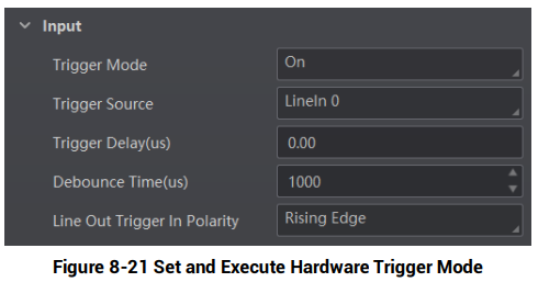
Set and Execute Hardware Trigger Mode
Steps
1. Click I/O Control Settings → Input → Trigger Mode.
2. Select On as Trigger Mode.
3. Select the specific line as Trigger Source according to actual demands.
4. Set Debounce Time and Line Out Trigger In Polarity according to actual demands.

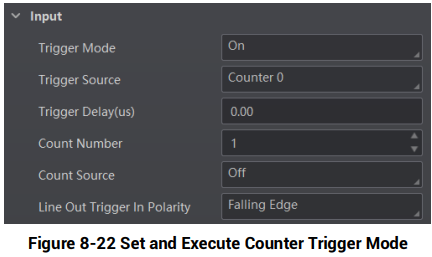
Set and Execute Counter Trigger Mode
Counter specifies that the trigger source will be generated after the set number of valid signals appears. For example, if you set the Count Number to 3, the trigger source will be generated after 3 signals appear.
Steps
1. Click I/O Control Settings → Input → Trigger Mode.
2. Select On as Trigger Mode.
3. Select Counter 0 as Trigger Source.
4. Set Trigger Delay, Count Number, Count Source and Line Out Trigger In Polarity according to actual demands.
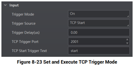
Set and Execute TCP Trigger Mode
TCP start specifies the TCP server as the source for the trigger signal. When the server receives the specified string text, the trigger signal will be outputted.
Click I/O Control Settings → Input → Trigger Mode, select On as Trigger Mode and select TCP Start as Trigger Source.
Set Trigger Delay, Tcp Trigger Port, and Tcp Start Trigger Text according to actual demands.
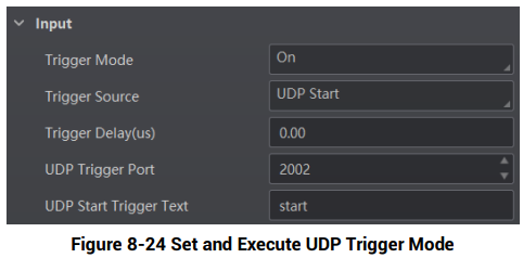
Set and Execute UDP Trigger Mode
UDP start specifies the UDP server as the source for the trigger signal. When the server receives the specified string text, the trigger signal will be outputted.
Click I/O Control Settings → Input → Trigger Mode, select On as Trigger Mode and select UDP Start as Trigger Source.
Set Trigger Delay, Udp Trigger Port, and Udp Start Trigger Text according to actual demands.
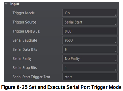
Set and Execute Serial Port Trigger Mode
Serial start specifies the serial port as the source for the trigger signal. When the serial port receives the specified string text, the trigger signal will be outputted.
Click I/O Control Settings → Input → Trigger Mode, select On as Trigger Mode and select Serial Start as Trigger Source.
Set Trigger Delay, Serial Baudrate, Serial Data Bits, Serial Parity, Serial Stop Bits, and Serial Start Trigger Text according to actual demands.
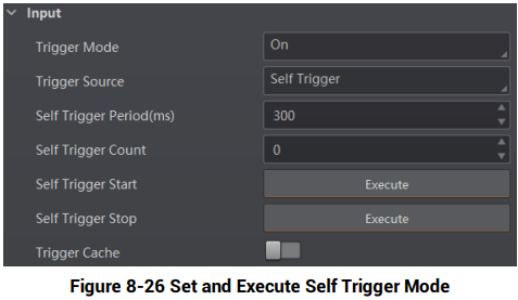
Set and Execute Self Trigger Mode
Self trigger mode allows you to trigger the device according to the trigger period you configured.
Steps
1. Click I/O Control Settings → Input → Trigger Mode.
2. Select On as Trigger Mode.
3. Select Self Trigger as Trigger Source, and set Self Trigger Period and Self Trigger Count.
4. Click Execute in Self Trigger Start to start, and click Execute in Self Trigger Stop to stop.
8.3.4 Stop Trigger
The device supports stopping trigger via TCP, UDP, I/O, and serial port. You can also set code reading timeout duration or max. barcode amount to be read to stop trigger. After stopping trigger is completed, the device cannot make response to trigger again.
Stop Trigger via IO
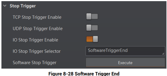
You can stop a trigger via IO: Enabling IO Stop Trigger Enable first, select specific sources from IO Stop Trigger Selector, and then set the trigger polarity as the condition to stop trigger.
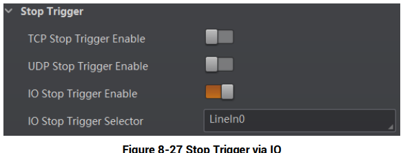
When selecting SoftwareTriggerEnd as IO Stop Trigger Selector, you can click Execute in Software Stop Trigger to stop current trigger.
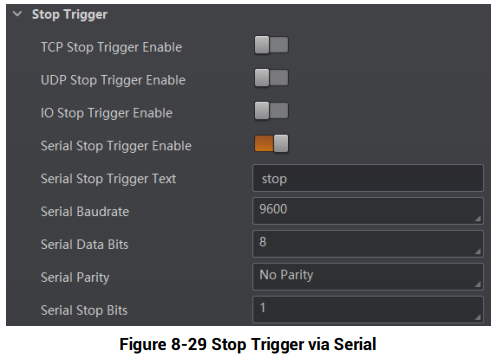
Stop Trigger via Serial
When the specified serial port receives the specified string text, the trigger will be stopped.
The client software sends stop trigger command to the device after Serial Stop Trigger Enable is enabled.
You should enter Serial Stop Trigger Text, Serial Baudrate, Serial Data Bits, Serial parity, and Serial Stop Bits according to actual demands. The Serial Baudrate includes 4800, 9600, 19200, 38400, 57600 and 115200, and Serial Data Bits is 8.
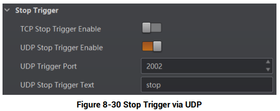
Stop Trigger via UDP
When the UDP server receives the specified string text, the trigger will be stopped. The client software sends stop trigger command to the device after Udp Stop Trigger Enable is enabled. You should enter Udp Trigger Port and Udp Stop Trigger Text according to actual demands. The range of Udp Trigger Port is from 1025 to 65535, and the default port is 2002.
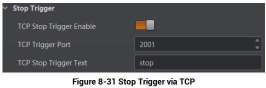
Stop Trigger via TCP
When the TCP server receives the specified string text, the trigger will be stopped. The client software sends stop trigger command to the device after Tcp Stop Trigger Enable is enabled. You should enter Tcp Trigger Port and Tcp Stop Trigger Text according to actual demands. The range of Tcp Trigger Port is from 1025 to 65535, and the default port is 2001.
Stop Trigger via Timeout Duration

When the trigger time reaches the specified maximum value (in ms), the trigger will be stopped. You can enable TimeOut Stop Trigger Enable, and set Maximum Output Limited
Time according to actual demands. The range of Maximum Output Limited Time is 0 to 10000 ms.

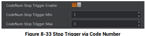
Stop Trigger via Code Number

This function means that the code quantity outputted by the device is restricted to the settings you configured here. You can enable CodeNum Stop Trigger Enable, and set CodeNum Stop Trigger Min and CodeNum Stop Trigger Max according to actual demands.
● If the outputted code quantity is smaller than configured CodeNum Stop Trigger Min, and the device will output codes continuously.
● If the outputted code quantity is smaller than configured CodeNum Stop Trigger Max, and the device will stop outputting codes.
● If the outputted code quantity is between configured CodeNum Stop Trigger Min and CodeNum Stop Trigger Max, and the device will read and output codes according to trigger signals.
● If CodeNum Stop Trigger Min is same with CodeNum Stop Trigger Max, and the device will stop outputting codes when the number of outputted codes reaches the configured number.
8.4 Signal Output Settings
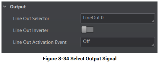
8.4.1 Select Output Signal
The device’s output signal can control external devices like PLC, flashing light, etc. Click I/O Control Settings → Output → Line Out Selector to select output signal.
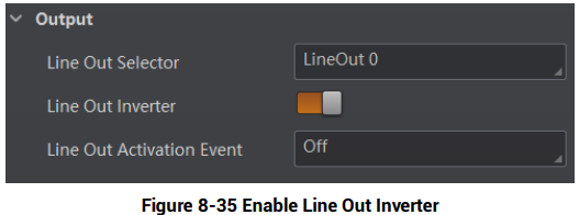
8.4.2 Enable Line Inverter
The level inverter function allows the device to invert the electrical signal level of an I/O line, and meets requirements of different devices for high or low electrical signal level.
You can go to I/O Control Settings → Output → Line Out Inverter to enable it.

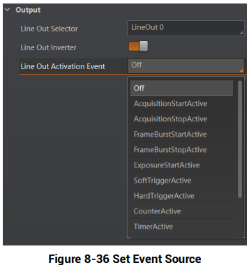
8.4.3 Set Event Source
The device supports outputting different trigger signals according to the event source you select.
Click I/O Control Settings → Output → Line Out Activation Event to select event source.
The device supports following event sources, including Off, Acquisition Start Active, Acquisition Stop Active, Frame Burst Start Active, Frame Burst Stop Active, Exposure Start Active, Soft Trigger Active, Hard Trigger Active, Counter Active, Timer Active, No Code Read, Read Success, and Light Strobe Long.

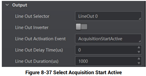
Select Acquisition Start Active
If acquisition starts, the output signal will be triggered. When you select Acquisition Start Active as Line Out Activation Event, you can set its output delay time and duration.
Line Out Delay Time
It sets the delay time for outputting the output signal.
Line Out Duration
It sets the time duration of the output signal.
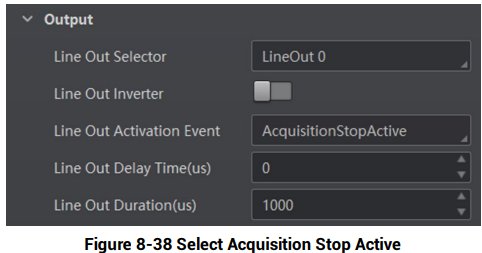
Select Acquisition Stop Active
If acquisition stops, the output signal will be triggered. When you select Acquisition Stop Active as Line Out Activation Event, you can set its output delay time and duration.
Line Out Delay Time
It sets the delay time for outputting the output signal.
Line Out Duration
It sets the time duration of the output signal.
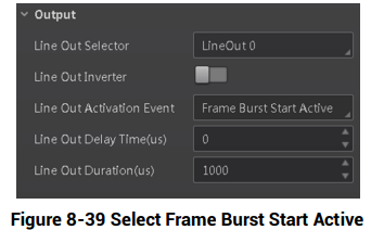
Select Frame Burst Start Active

If the burst of a frame starts, the output signal will be triggered. When you select Frame Burst Start Active as Line Out Activation Event, you can set its output delay time and duration.
Line Out Delay Time
It sets the delay time for outputting the output signal.
Line Out Duration
It sets the time duration of the output signal.
Select Frame Burst Stop Active

If the burst of a frame stops, the output signal will be triggered. When you select Frame Burst Stop Active as Line Out Activation Event, you can set its output delay time and duration.
Line Out Delay Time
It sets the delay time for outputting the output signal.
Line Out Duration
It sets the time duration of the output signal.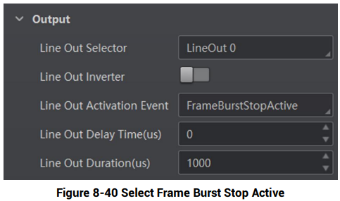
Select Exposure Start Active

If you select Exposure Start Active as Line Out Activation Event, you can set its output delay time, duration, and ahead time.
Line Out Delay Time
It sets the delay time for outputting the signal.
Line Out Duration
It sets the duration for outputting the signal.
Line Out Ahead Time
It sets the ahead time for outputting the signal.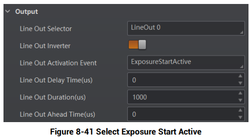
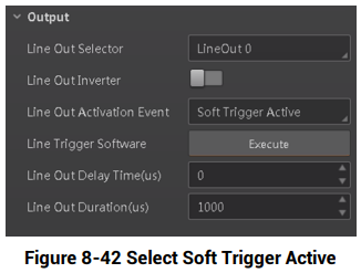
Select Soft Trigger Active
If you select Soft Trigger Active as Line Out Activation Event, you can set its output delay time, duration, and execute outputting signal manually.
Line Out Delay Time
It sets the delay time for outputting the output signal.
Line Out Duration
It sets the time duration of the output signal.
Line Trigger Software
Click Execute for manually outputting the output signal.
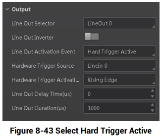
Select Hard Trigger Active
If you select Hard Trigger Active as Line Out Activation Event, you can set its output delay time, duration, trigger source, and trigger activation.
Line Out Delay Time
It sets the delay time for outputting the output signal.
Line Out Duration
It sets the time duration of the output signal.
Hardware Trigger Source
It sets the hardware trigger source, including LineIn 0, LineIn 1, and LineIn 2.
Hardware Trigger Activation
It sets the trigger activation of input signal, including Rising Edge and Falling Edge.
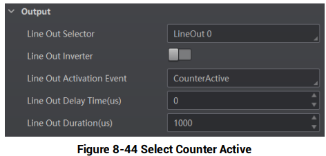
Select Counter Active
Counter active means that the counter triggers the output signal. When you select Counter Active as Line Out Activation Event, you can set its output delay time and duration.
Line Out Delay Time
It sets the delay time for outputting the output signal.
Line Out Duration
It sets the time duration of the output signal.
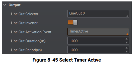
Select Timer Active
If you select Timer Active as Line Out Activation Event, you can set its output duration and period.
Line Out Duration
It sets the time duration of the output signal.
Line Out Period
It sets the time period of the output signal.
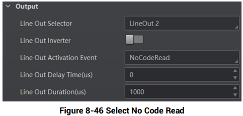
Select No Code Read
If you select No Code Read as Line Out Activation Event, you can set its output delay time and duration.
Line Out Delay Time
It sets the delay time for outputting the output signal.
Line Out Duration
It sets the time duration of the output signal.
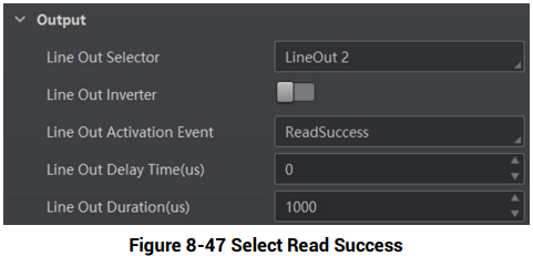
Select Read Success
If you select Read Success as Line Out Activation Event, you can set its output delay time and duration.
Line Out Delay Time
It sets the delay time for outputting the output signal.
Line Out Duration
It sets the time duration of the output signal.
Select Light Strobe Long
If you select Light Strobe Long as Line Out Activation Event, you do not need to set any parameters.
8.5 Code Reading Result Settings
In Data Processing module, you can set filter rules for reading barcodes and other data processing related parameters.
8.5.1 Set Code Reading Result Output Mode
There are 2 types of output modes when the device mode is Normal and trigger mode is On: Instant output mode and non-instant output mode.
● Instant output mode means that the device can instantly output code reading results when recognizing codes if you enable Instant Output Mode Enable in Filter Rule.
● Non-instant output mode means that the device does not output code reading results it recognized until the trigger stops if Instant Output Mode Enable is not enabled. If the device does not recognize any codes during the whole process, images it captured will be output, and you can set which images to be outputted in NoRead Image Index.
When the device mode is Normal and trigger mode is Off, you can set Filter Time in Filter Rule. Within the configured Filter Time, the device will not output any code information

8.5.2 Set Filter Rule
You can set rules to filter unwanted barcodes to improve the reading efficiency in Filter Rule.
Two filter modes are available, including normal mode and regular expression mode. You can set it in Filter Mode.

Normal Filter Mode
When the device mode is Normal, Trigger Mode is On, and Filter Mode is Normal, you can set the following parameters according to actual demands.
Instant Output Mode Enable
If this parameter is enabled, the device can instantly output code reading result when recognizing codes. If it is not enabled, the device will not output code reading result until the trigger stops.
Min. Output Time
It sets the min. waiting time before data output. For example, if you set 500 ms as Minimum Output Time, the barcode would not be outputted until 500 ms is passed.
Numeral Filter
If this parameter is enabled, the device will only parse and read the numeral contents of the barcodes, and the non-numeral contents will be filtered out.
Max Output Length
It sets the max. code length that can be outputted.
Code Offset Num
It sets the range of barcode to be filtered. For example, the barcode is ABCDEFG, if you set this parameter as 2, the device will output CDEFG at last and filter AB.
Begin with Specific Character for Result
If this parameter is enabled, the device will only read the barcodes which begin with a specific character. Otherwise, the barcodes will be filtered out. You can enter the specific character in Begin with.
Include Specific Character in Barcode
If this parameter is enabled, the device will only read the barcodes which include a specific character. Otherwise, the barcodes will be filtered out. You can enter the specific character in Character.
Exclude Specific Character in Barcode
If this parameter is enabled, the device will only read the barcodes which exclude a specific character. Otherwise, the barcodes will be filtered out. You can enter the specific character in Character.
Min. Code Length
If the length of a barcode is shorter (in terms of the number of characters contained in the barcode) than the configured value, the device will not parse the contents of the barcode. The valid value is from 1 to 256. For example, if you set the value as 6, the device will not parse the contents of the barcodes which contain less than 6 characters.
Max. Code Length
If the length of a barcode is longer ((in terms of the number of characters contained in the barcode) than the configured value, the device will not parse the contents of the barcode. The valid value is from 1 to 256. For example, if you set the value as 9, the device will not parse the contents of the barcodes which contain more than 9 characters.
Read Times Threshold
If the reading results of a barcode is same for the configured times, the barcode will be regarded as valid and its reading result will be outputted. Or the barcode will be regarded as invalid and its reading result will not be outputted.
De-duplication Enable
If it is enabled, the repeated code information will be filtered within specific trigger times. You can set trigger times in De-duplication Windows Size, and its default value is 1.
De-duplication By ROI
If it is enabled, the device will filter information based on drawn ROIs.
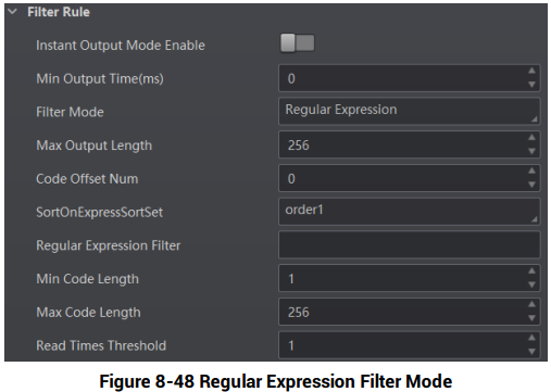
Regular Expression Filter Mode
Instant Output Mode Enable
If this parameter is enabled, the device can instantly output code reading result when recognizing codes. If it is not enabled, the device will not output code reading result until the trigger stops.
Min. Output Time
It sets the min. waiting time before data output. For example, if you set 500 ms as Minimum Output Time, the barcode would not be outputted until 500 ms is passed.
Max Output Length
It sets the max. code length that can be outputted.
Code Offset Num
It sets the range of barcode to be filtered. For example, the barcode is ABCDEFG, if you set this parameter as 2, the device will output CDEFG at last and filter AB.
Regular Expression
It selects the regular expression from order 1 to order 10. You can enter specific regular expression contents in Regular Expression Filter. Up to ten regular expression rules can be set at the same time. Once one regular expression is met, code can be outputted.
Regular Expression Filter
It sets the specific regular expression contents.
Min. Code Length
If the length of a barcode is shorter (in terms of the number of characters contained in the barcode) than the configured value, the device will not parse the contents of the barcode. The valid value is from 1 to 256. For example, if you set the value as 6, the device will not parse the contents of the barcodes which contain less than 6 characters.
Max. Code Length
If the length of a barcode is longer ((in terms of the number of characters contained in the barcode) than the configured value, the device will not parse the contents of the barcode. The valid value is from 1 to 256. For example, if you set the value as 9, the device will not parse the contents of the barcodes which contain more than 9 characters.
Read Times Threshold
If the reading results of a barcode is same for the configured times, the barcode will be regarded as valid and its reading result will be outputted. Or the barcode will be regarded as invalid and its reading result will not be outputted.
8.5.3 Set Result Format
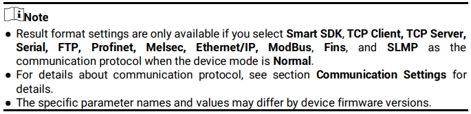
Result format settings allow you to set the format and contents contained in the outputted barcode information. Result format is related to communication protocol and trigger mode.
With different selected communication protocol and trigger mode, you need to set corresponding parameters.
Result Output via Smart SDK
When the communication protocol is Smart SDK, device mode is Normal and trigger mode is On, you can set following parameters.
Sorting Rules
It decides the output order of codes, and you can select it according to actual demands.
One By One Enable
If it is enabled, the device will send one piece of code information each time in accordance with the specified interval. You can set the interval via One By One Interval and the default value 100 ms.
Local Save Picture Mode
It includes Off and NoRead. You can select NoRead to let the device save images when no code is read.
Local Picture Type
It sets the image saving type, including JPEG and BMP.
Local Override Strategy
It includes Off, Max Count, Loop Max Count, and Reserve Space. Off means that disk will not be overridden. Max Count means that the device will save image quantity configured in Local Override Max. Count, and no more imaged will be saved when the disk is full. Loop Max Count means that after the image quantity is reached the number configured in Local Override Max. Count, the device will delete the first image and continue to save the latest image. Reserve Space means that the device will save images when the disk is safe in terms of storage space If the available disk space is lower than configured value, and images will be deleted.
Local Override Max. Count
You need to set this parameter when selecting Max Count or Loop Max Count as Local Override Strategy.
Local Picture Name Content
It selects what contents you want to display in file name, including frame time, trigger No. and frame No.
Local Time Format
It selects a format type from the drop-down list for the time stamp contained in the file name. Take YYYYMMDD_HHMMSSFFF as an example, (from the left to the right) YYYY represents year, MM represents month, DD represents date, HH represents hour, MM represents minute, SS represents second, and FFF represents millisecond.
Local Save Picture Strategy
It sets the picture saving method. Four methods are available, including recently frame, all frames, range frames and specific frame. If specific frame is selected as Local Save Picture Strategy, you need to set Local Picture Index.
Result Output via FTP
The device also supports using the FTP communication protocol to send and receive data, and you can select it to output information. The configurable parameters below are related to the trigger mode, and here we take the external trigger mode as an example.
Sorting Rules
It decides the output order of codes, and you can select it according to actual demands.
One By One Enable
If it is enabled, the device will send one piece of code information each time in accordance with the specified interval. You can set the interval via One By One Interval and the default value 100 ms.
Local Save Picture Mode
It includes Off and NoRead. You can select NoRead to let the device save images when no code is read.
Local Picture Type
It sets the image saving type, including JPEG and BMP.
Local Override Strategy
It includes Off, Max Count, Loop Max Count, and Reserve Space. Off means that disk will not be overridden. Max Count means that the device will save image quantity configured in Local Override Max. Count, and no more imaged will be saved when the disk is full. Loop Max Count means that after the image quantity is reached the number configured in Local Override Max. Count, the device will delete the first image and continue to save the latest image. Reserve Space means that the device will save images when the disk is safe in terms of storage space If the available disk space is lower than configured value, and images will be deleted.
Local Override Max. Count
You need to set this parameter when selecting Max Count or Loop Max Count as Local Override Strategy.
Local Picture Name Content
It selects what contents you want to display in file name, including frame time, trigger No. and frame No.
Local Time Format
It selects a format type from the drop-down list for the time stamp contained in the file name. Take YYYYMMDD_HHMMSSFFF as an example, (from the left to the right) YYYY represents year, MM represents month, DD represents date, HH represents hour, MM represents minute, SS represents second, and FFF represents millisecond.
Local Save Picture Strategy
It sets the picture saving method. Four methods are available, including recently frame, all frames, range frames and specific frame. If specific frame is selected as Local Save Picture Strategy, you need to set Local Picture Index.
Output Retrans Enable
If this parameter is enabled, the data is allowed to retransmit to FTP server, and you should set specific value in Output Retrans Number.

FTP Picture Name Content
It selects what contents you want to display in FTP file name, including code content, code type, frame number, etc. You can select multiple contents as desired, and the selected contents will be displayed below.
FTP Transmission Conditions
It sets the condition to upload the data outputted by the device to FTP server. All refers to upload the data always. Read Barcode refers to upload the data only when the barcode is read by the device. No Read Barcode refers to upload the data only when no barcode is read by the device.
FTP Transmission Result Contain
It selects contents to upload to the FTP server. Just Result refers to only upload the content of the barcode. Just Picture refers to only upload the barcode picture. Result and Picture refers to upload both the content of the barcode and the picture.
FTP Time Format
It selects a format type from the drop-down list for the time stamp contained in the file name. Take YYYYMMDD_HHMMSSFFF as an example, (from the left to the right) YYYY represents year, MM represents month, DD represents date, HH represents hour, MM represents minute, SS represents second, and FFF represents millisecond.
FTP Result Prefix
It sets the prefix of FTP file name, including No, Result and All. No stands for no prefix for file name, and all images are saved in FTP root directory. Result stands for all images that code reading successfully will be saved in Read directory, and all images that code reading failed will be saved in Noread directory. All stands for all images will be saved in All directory.
FTP Save Picture Strategy
It sets the FTP picture saving method when no code is read. Four methods are available, including recently frame, all frames, range frames and specific frame. If specific frame is selected as FTP Save Picture Strategy, you need to set FTP Picture Index.
Result Output via Other Communication Protocols
When the communication protocol is TCP Client, TCP Server, Serial, Profinet, Melsec, Ethernet/IP, ModBus, Fins or SLMP, device mode is Normal and trigger mode is On, you can set following parameters.

Sorting Rules
It decides the output order of codes, and you can select it according to actual demands.
One By One Enable
If it is enabled, the device will send one piece of code information each time in accordance with the specified interval. You can set the interval via One By One Interval and the default value 100 ms.
ROI Output NoRead Enable
If it is enabled, codes will be outputted in turn according to the ROI Selector of the algorithm ROI they belong.
Local Save Picture Mode
It includes Off and NoRead. You can select NoRead to let the device save images when no code is read.
Local Picture Type
It sets the image saving type, including JPEG and BMP.
Local Override Strategy
It includes Off, Max Count, Loop Max Count, and Reserve Space. Off means that disk will not be overridden. Max Count means that the device will save image quantity configured in Local Override Max. Count, and no more imaged will be saved when the disk is full. Loop Max Count means that after the image quantity is reached the number configured in Local Override Max. Count, the device will delete the first image and continue to save the latest image. Reserve Space means that the device will save images when the disk is safe in terms of storage space If the available disk space is lower than configured value, and images will be deleted.
Local Override Max. Count
You need to set this parameter when selecting Max Count or Loop Max Count as Local Override Strategy.
Local Picture Name Content
It selects what contents you want to display in file name, including frame time, trigger No. and frame No.
Local Time Format
It selects a format type from the drop-down list for the time stamp contained in the file name. Take YYYYMMDD_HHMMSSFFF as an example, (from the left to the right) YYYY represents year, MM represents month, DD represents date, HH represents hour, MM represents minute, SS represents second, and FFF represents millisecond.
Local Save Picture Strategy
It sets the picture saving method. Four methods are available, including recently frame, all frames, range frames and specific frame. If specific frame is selected as Local Save Picture Strategy, you need to set Local Picture Index.
Profinet Output Format
It selects what contents you want to output, including code content, code type, angle, trigger start time, code score, etc. You can select multiple contents according to actual demands.
Profinet Format Check
You should click Execute in Profinet Format Check to check if you entered is right in format, and the check result will be displayed in Profinet Format Check Result.
Profinet Output NoRead
If it is enabled, and the device will output the content you set in Profinet Output NoRead Text when no code is recognized.
Profinet Output Start Text
The contents of the start part of the data outputted. You can set the contents according
to actual condition.
Profinet Output Stop Text
The contents of the end part of the data outputted. You can set the contents according to actual condition.
Profinet Output Barcode Enter Character Enable
If it is enabled, enter character will be outputted.
Profinet Output Barcode Newline Character Enable
If it is enabled, a newline will be outputted.
Profinet Output Barcode Carriage Return Enable
If it is enabled, a carriage return will be outputted.
Profinet Add NoRead Enable
You can add contents to let the device output codes when the code recognized by the device does not meet the min. length requirement. It includes Off, Add Noread, and Just Noread. Off does not add contents and the device outputs code recognized only. Add Noread allows you to add contents to the min. length requirement and output. Just Noread means that the device outputs Noread only if the code recognized by the device does not meet the min. length requirement.
Code Pos Width Enable
If it is enabled, you can add 0 to codes if the code coordinate does not meet specified length.
Code Pos Width
You can enter the length of the code coordinate after enabling Code Pos Width Enable.
CodeNum End Trigger Min
If it is enabled, the device will stop triggering and save the current image when the code recognized by the device does not meet the min. length requirement.
8.6 Contrast Control Settings

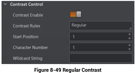
The contrast control function compares the data that the device reads with preset data and outputs contrast result. The result can be used as the event source of trigger signal, including Contrast Success and Contrast Fail. This function has two ways to contrast, including regular contrast and consecutive number contrast.
Regular Contrast
The regular contrast requires you to set code contents in advance, and the client software will contrast the data that the device reads with preset contents and outputs comparison result.
Steps
1. Right click the device in Device Connection, and click Feature Tree.
2. Go to Contrast Control, enable Contrast Enable, and select Regular as Contrast Rules.
3. Set Start Position that means the stating position of the comparison.
4. Set Character Number that means the comparison quantity.
5. Set code contents in Wildcard String.

Consecutive Number Contrast
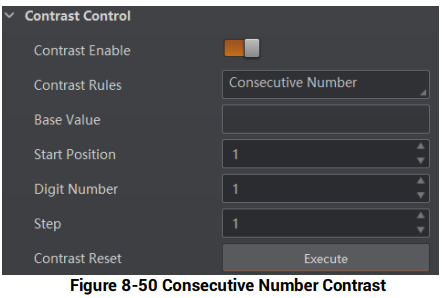
The consecutive number contrast requires you to set consecutive code rules, and the client software will contrast the data that the device reads with preset rules and outputs contrast result.
Steps
1. Right click the device in Device Connection, and click Feature Tree.
2. Go to Contrast Control, enable Contrast Enable, and select Consecutive Number as Compare Rules.
3. Set Start Position that means the stating position of the comparison.
4. Set Digital Number that means the comparison quantity.
5. Set Step that means the client software will increase or decrease the preset value after each comparison according the step you set.

6. (Optional) Click Execute in Contrast Reset to reset comparison. After that, the client software will use the first code it reads as the preset value.
Here we take start position (3), digital number (2) and step (2) as an example to explain the consecutive number comparison:
● If the first code that the device reads is ur96k, and then the preset value is 96. The preset value increases to 98 (96+2).
● If the second code is yr98kjkfd, and comparison succeeds. The preset value increases to 100 (98+2).
● If the third code is kl99fjkd, and comparison fails. The preset value does not increase.
● If the fourth code is kl00djf, and comparison succeeds. The preset value increases to 02 (00+2).
8.7 Communication Settings
The communication protocol is used to transmit and output code reading result and image. The communication protocol is related to the device modes. With various device modes, the device supports different communication protocols and corresponding parameters. When the device mode is Test or Raw, the device only supports Smart SDK protocol and no parameter settings are required. While in Normal mode, the device supports Smart SDK, TCP Client, TCP Server, Serial, FTP, Profinet, Melsec, Ethernet/IP, ModBus, Fins and SLMP communication protocols, and you need to set corresponding parameters.

8.7.1 Smart SDK
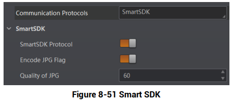
If Smart SDK is selected as the Communication Protocols, you can enable SmartSdk Protocol to let the device output data via Smart SDK.
Encode JPG Flag
If enabled, the device will compress the image data.
Quantity of Jpg
You can enter a number (range: 50 to 99) to determine the compression quality
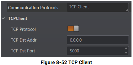
8.7.2 TCP Client
The TCP includes TCP Server and TCP Client. If TCP Client is selected as the Communication Protocols, you can enable TCP Protocol, and enter TCP Dst Addr and TCP Dst Port.
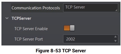
8.7.3 TCP Server
The TCP includes TCP Server and TCP Client. If TCP Server is selected as the Communication Protocols, you can enable TCP Server Enable, and enter TCP Server Port.
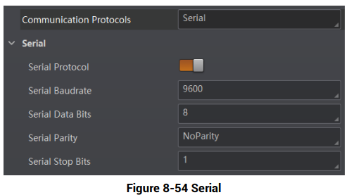
8.7.4 Serial
If Serial is selected as the Communication Protocols, you can enable Serial Protocol, enter Serial Baud Rate, Serial Data Bits, Serial Parity, and Serial Stop Bits.
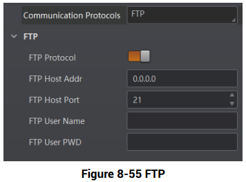
8.7.5 FTP
If FTP is selected as the Communication Protocols, you can enable FTP Protocol, enter FTP Host Addr, FTP Host Port, FTP User Name, and FTP User PWD.
8.7.6 Profinet
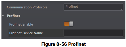
If Profinet is selected as the Communication Protocols, you can enable Profinet Enable and set Profinet Device Name according to actual demands.
8.7.7 MELSEC
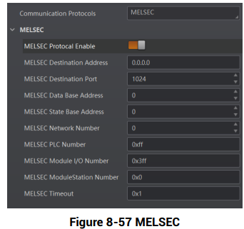
If MELSEC is selected as the Communication Protocols, you can enable MELSEC Protocol Enable and set related parameters according to actual demands.
MELSEC Destination Address
It sets the IP address of the target PLC.
MELSEC Destination Port
It sets the port number of the target PLC.
MELSEC Data Base Address
It sets the first address of the data area.
MELSEC State Base Address
It sets the first address of the status area.
MELSEC Network Number
It sets the network No.
MELSEC PLC Number
It sets the PLC No.
MELSEC Module I/O Number
It sets the target module’s I/O number.
MELSEC Module Station Number
It displays the module station number.
MELSEC Timeout
It sets the waiting time before the returning of PLC’s response.
8.7.8 Ethernet/IP
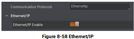
If Ethernet/IP is selected as the Communication Protocols, you can enable Ethernet/IP Enable, and the device will output data via Ethernet/IP.
8.7.9 ModBus
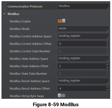
If ModBus is selected as the Communication Protocols, you can enable ModBus Enable and set related parameters according to actual demands.
ModBus Mode
It includes server and client, and is server by default.

ModBus Control Address Space
It is holding_register by default.
ModBus Control Address Offset
It refers to the address offset, and is 0 by default.
ModBus Control Data Number
It is 2 by default.
ModBus State Address Space
It is input_register by default.
ModBus State Address Offset
It is 0 by default.
ModBus State Data Number
It is 2 by default.
ModBus Result Address Space
It is input_register by default.
ModBus Result Address Offset
It is 4 by default.
ModBus String Byte Swap
If it is enabled, string byte is saved by big-endian. If it is not enabled, string byte is saved by little-endian.
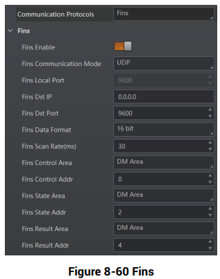
8.7.10 Fins
If Fins is selected as the Communication Protocols, you can enable Fins Enable and set related parameters according to actual demands.
Fins Communication Mode
It includes UDP or TCP.
Fins Local Port
It is 9600 by default.
Fins Dst IP
It sets the IP address of the target device.
Fins Dst Port
It sets the port of the target device.
Fins Data Format
It includes 16-bit or 32-bit.
Fins Scan Rate (ms)
It sets the interval that the device reads the server’s control register, and the unit is ms.
Fins Control Area
It is saved in DM area by default.
Fins Control Addr
You can set it according to actual demands. Make sure that each area cannot be overlapped and covered.
Fins State Area
It is saved in DM area by default.
Fins State Addr
You can set it according to actual demands. Make sure that each area cannot be overlapped and covered.
Fins Result Area
It is saved in DM area by default.
Fins Result Addr
You can set it according to actual demands. Make sure that each area cannot be overlapped and covered.
8.7.11 SLMP
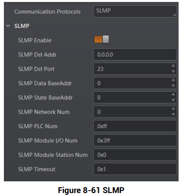
If SLMP is selected as the Communication Protocols, you can enable SLMP Enable and set related parameters according to actual demands.
SLMP Dst Addr
It sets the IP address of the target PLC.
SLMP Dst Port
It sets the port number of the target PLC.
SLMP Data Base Addr
It sets the first address of the data area.
SLMP State Base Addr
It sets the first address of the status area.
SLMP Network Num
It sets the network No.
SLMP PLC Num
It sets the PLC No.
SLMP Module I/O Num
It sets the target module’s I/O number.
SLMP Module Station Num
It displays the module station number.
SLMP Timeout
It sets the waiting time before the returning of PLC’s response.
8.8 User Set Customization
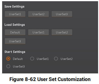
The Configuration Management module allows you to set and manage the user set. A user set is a group of parameter values with all the settings needed to control the device, and you can save, load and switch different user sets.
Save Settings
If you have set the device parameters as desired, you can save them into the user set. Go to Config Management → Save Settings, and click UserSet1, UserSet2, or UserSet3 to save the current device settings.
Load Settings
You can load the user set to restore the device to the saved group of parameter values again if required. Go to Config Management → Load Settings, and click Default, UserSet1, UserSet2, or UserSet3 to load settings.

Start Settings
The selected user set will be automatically loaded after the device being powered on.
For example, if you select Default, the device parameter settings will be restored to the factory settings.
8.9 Statistics Information
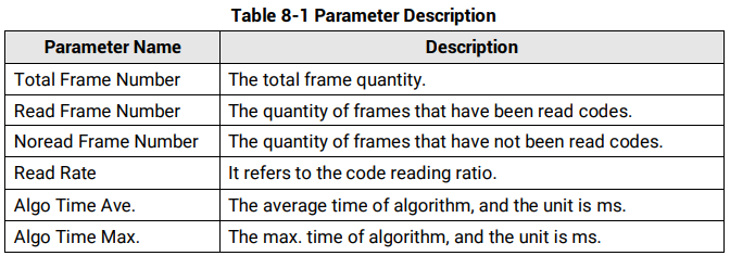
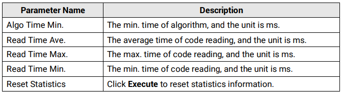
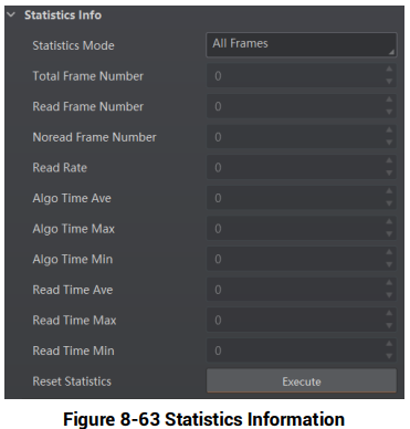
The statistics information in the feature tree helps you to count data related with code reading.

Go to feature tree, find Statistics Info., and select Statistics Mode according to actual demands. Two statistics modes are available:
All Frames means that the client software will display all data since the device is powered on. Latest Frames means that the client software will display data of the last 10 frames. Refer to the table below for specific parameters.
8.10 Event Report
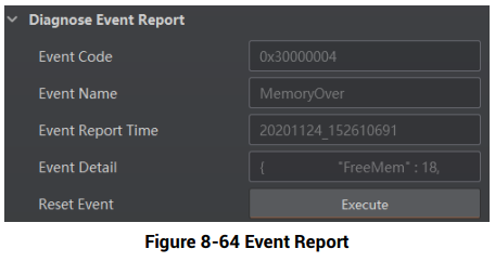
The diagnose event report function in the feature tree monitors memory and CPU usage rate, and let you know when there is a crash, higher CPU usage rate, insufficient memory, and other events.
Go to feature tree, find Diagnose Event Report, and you can view related information as shown below. You can click Execute in Reset Event to clear all information.