
6. Device Configuration
After connecting devices to the Software, you can configure the device parameters to determine the optimal settings for barcode reading.
Note
It is recommended that you start live view before configuring device parameters. For details about live view, see Acquisition and Live View.
6.1 Device Connection and Management
You should connect devices to the Software for further configuration. In the device list, you can performoperations after adding devices, such as configuring device IP address, renaming device user ID, and resetting device. In the Device Control area, you can set the device to work automatically and synchronize time. In the Device Information area, you can view the basic information of the selected device.
6.1.1 Connect Device
You can connect devices to the Software in two ways, i.e., connecting auto-enumerated local devices, or adding remote devices.
Connect Enumerated Local Device
All the devices on the same local subnet with the PC running the Software will be automatically enumerated on the device list.
Click Settings → General, and switch on Device List Auto-Enumeration to enumerate all local devices.
Note
When multiple NICs are connected to the same network segment, the Software will
enumerate the devices for all the NICs respectively.
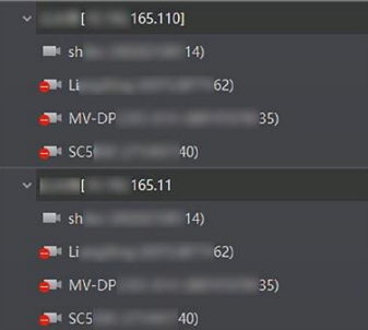
Figure 6-1 Enumerate Devices for Two NICs in the Same Network Segment
For auto-enumerated devices, you can perform the following operations.
● Click Device Connection to display the device list, select a device, and click  to connect it to the Software.
Note
The icon beside the device name shows the device status.
● Click  to refresh the devices on the same local subnet, or enable auto-refreshing. For details about auto-refreshing local devices, see General Settings.
● Add devices to groups for further management. For details, see Group Cameras.
● Enter the device name, model name, serial number, and/or IP address, and click  to search for devices.
● Click  → Device Name / Model Name / Serial Number / IP Address to sort the devices.
● Click Settings → General, and switch on Filter Camera Model and set the filtering tag of a device model for not displaying that device model in the device list.
Note
This function will take effect after you restart the Software.
● You can set the device enumeration protocol(s) to standard protocol, private protocol, or standard and private protocol. See details in General Settings.
Connect a Camera by CMD
You can launch the Software and connect devices by CMD command.
Steps
1. Open the CMD window in the PC system.
2. Enter cd and the file path of IDMVS.exe, then press Enter.
Example
If the path of IDMVS.exe is C:\Program Files (x86)\IDMVS\Applications\Win64, then you should enter cd C:\Program Files (x86)\IDMVS\Applications\Win64, as shown in the picture below.

Figure 6-2 Connect to the Software via CMD Command
3. Connect to a device with CMD command in one of the following ways.
1) Connect via device IP address. Enter IDMVS.exe/IP xx.xx.xx.xx, then press Enter.

Figure 6-3 Connect a Device via IP Address
2) Connect via device MAC address. Enter IDMVS.exe/Mac xx.xx.xx.xx.xx.xx, then press Enter.
3) Connect via device serial No. Enter IDMVS.exe/SN xxxxxxxx, then press Enter.
Result
With all the steps above, you can open the Software and connect a device.
Add Remote Camera
You can add GigE Vision camera NOT in the same local subnet with the client software to the device list.
Steps
1. Right-click the network interface card (for example, Local Area Connection in the following picture) to open the right-click menu.
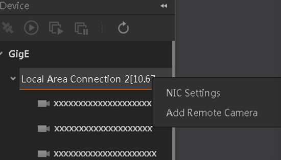
Figure 6-4 Right-click Menu
2. Click Add Remote Camera to open the Add Remote Camera window.
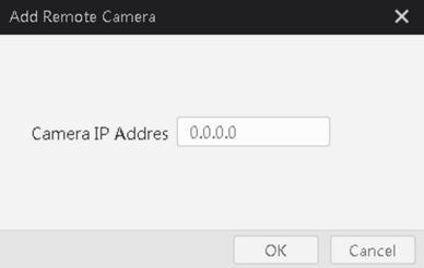
Figure 6-5 Add Remote Camera
3. Enter the camera IP address and then click OK to add the camera.
6.1.2 Device Status
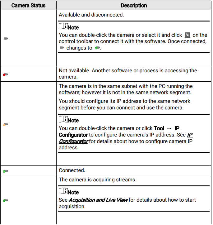
The Software provides multiple icons to indicate the device status. You can do further management according to the device status. For example, if the device status is "Connected", you can start acquiring streams or viewing the live video of the device.
The following table shows the descriptions of the status of the GigE Vision camera on the device list.
6.1.3 Edit IP Address of a Single Camera
You can modify the IP address of a single camera if the camera status is Free or Unreachable.
Steps
1. Select a network interface.
2. Double-click any place in the camera row to open the Modify IP Address window.
3. Select the Static IP, DHCP, or LLA as the IP type.
Note
You can change the IP type only when the camera status is Free. And if you change the IP type, the camera will be reset to its power up state.
Static IP
For setting the IP type as Static IP, you can modify the IP address, subnet mask, and default gateway.
DHCP
The camera is set to automatically obtain an IP address. This means that the IP address will dynamically change (within a range) every time the camera or computer is restarted.
Note
● If the IP addresses of your PC and camera are both static but they are not in the same IP segment, you need to change the camera IP address to a dynamic IP address.
● If you enter restricted IP types including D type (from 224 to 239), E type (from 240 to 254), the IP addresses starting with 127 or 255, or IP addresses with incorrect IP address formats, you will not be able to access the devices.
LLA
The camera uses a default IP address from the link-local address block. Link-local addresses for IPv4 are defined in the address block 169.254.0.0/16 in CIDR notation. In IPv6, they are assigned the address block fe80::/10.
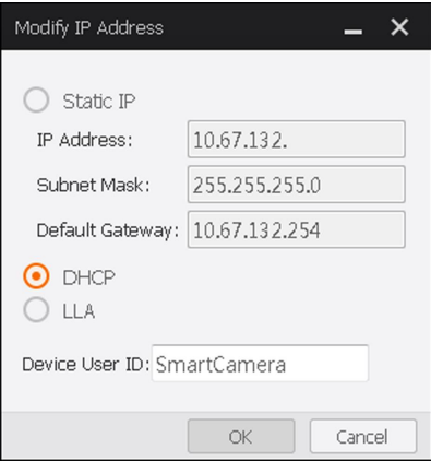
Figure 6-6 Modify IP Address
4. Optional: Edit the camera name in Device User ID field.
5. Click OK to save the settings.
Note
If the modified IP address conflicts with another device's IP address in the same local subnet, a prompt will pop up to remind you that IP conflict occurs. Change the IP address in this situation.
6.1.4 Group Cameras
You can custom camera group(s) on Device Configuration Wizard Panel.
Steps
1. Right-click the GigE list, and click Add Group to add a new group to the device list.
2. Optional: You can perform the following operations.
Rename You can rename the new group if needed.
Delete Group You can delete the new group if needed.
3. Right-click the camera, and click Move to Group to open the Switch Group page.
4. Select a group name to add the camera, and click OK.
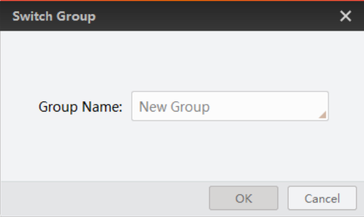
Figure 6-7 Switch Group
You can view camera information in the new group.
5. Optional: Right-click the camera on the list, and click Remove from Group to remove the camera from the group.
The camera will be on the original place of the device list.
6.1.5 Feature Tree
When a device is connected, all of the camera's features will be displayed on the feature tree.
Right-click a connected device and then click Feature Tree to display the feature tree.
● Click  to switch between Chinese and English.
● Click  to unfold or fold all parameters in the feature tree.
● Click  to import parameters to the feature tree, or export parameters in the feature tree to the PC as an MFS file.
● Click  to import or export device features. See File Access.
● Click  to refresh parameters in the feature tree.
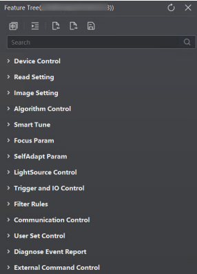
Figure 6-8 Feature Tree
Note
The features displayed vary with the camera model, firmware version, and running mode (Normal, Test).
6.1.6 File Access
You can export the feature configuration of a connected device to the local PC as a binary file, or import a binary file containing the feature configuration information from the local PC to a connected device.
Note
● This function should be supported by the device.
● This function is not available if you start acquisition.
Import Feature
Perform the following task to import feature configuration information to a connected device.
Steps
1. Click Device Connection to display the device list, and then select a device and click to connect it to the Software.
2. Right-click a device, and then click File Access to display the File Access window.
3. Click Import and select the corresponding MFA file to import the features saved in the file to the device.
Note
The Software only supports importing between cameras of the same model.
4. Optional: You can also batch import a feature configuration file to multiple devices of the same model using the File Access tool if needed.
1) On the top menu bar, select Tool → File Access to open the File Access Tool window.
2) Select devices (whose status are "Free") accordingly and select the corresponding MFA file from a local folder.
3) Click Import on the top right to import the features saved in the file to the selected devices.
Note
You can check the import progress and result of each device in the Import Status column.
5. Reboot the camera for the configurations of the imported file to take effect.
Export Feature
Perform the following task to export feature configuration information of a connected device to the local PC.
Steps
1. Click Device Connection to display the device list, and then select a device and click  to connect it to the Software.
2. Right-click a device, and then click File Access to display the File Access window.
3. From the drop-down list, select a device feature to be exported.
Note
You may also select License Notice from the drop-down list to export the license notice to the local PC as an MFA file. A TXT file for the license notice can then be generated based on the MFA file exported.
4. Click Export.
Note
● The exported file is in MFA format by default.
● The name of the exported file is "Device Model + Device Serial Number + Feature Name" by default.
Example
MV-ID5060M-08S-WBN_00F45884701_UserSet1.mfa
5. Optional: Click View on the prompt message to open the folder in which the exported file is saved.
6.1.7 Firmware Updater
You can update device firmware via the device list.
Steps
1. Select an available device in the device list, and select TCP upgrade mode or UDP upgrade mode according to your need.
Note
TCP upgrade mode should be supported by the device.
– TCP Upgrade Mode: After connecting to a camera, right-click the camera, and select Firmware Update. Enter the Update Port and click  to select the DAV file of firmware program according to the device model.
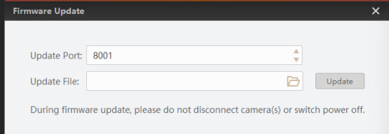
Figure 6-9 Firmware Upgrade-TCP
Note
The firmware upgrader does not support upgrading in TCP mode.
– UDP Upgrade Mode: right-click an available camera and select Firmware Update. Click  to select the DAV file of firmware program according to the device model. Click Update and you can view the progress of firmware update.
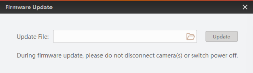
Figure 6-10 Firmware Update
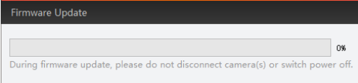
Figure 6-11 Firmware Update Progress
2. When the update finishes, a pop-up window will prompt the update success, and the device will reboot automatically.
6.1.8 Other Functions
The device list provides other functions such as saving GenICam XML and renaming device user ID.
● Right-click the network interface and then click NIC Settings to configure the properties of network interface card.
● Right-click a connected device and then click Rename User ID to edit the device user ID.
● Right-click a connected device and then click Save GenICam XML to save the camera information as XML file for secondary development.
● Right-click a connected device and then click Export EMMC Storage to export file stored on the device to the local PC.
Note
The function should be supported by the device.
● Right-click a connected device and then click Device Reset to reset the device to its power up state.
● Right-click a connected device and then click Auto Work to enable the device to enter working mode automatically when powered on.
● In Device Control, click Timingon the right of Auto Work to open the Time Calibration window, and select Manual Timing or NTP Timing
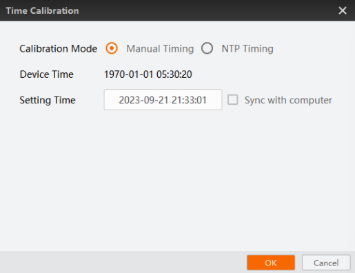
Figure 6-12 Manual Timing
Manual Timing
Device Time
The current time of the camera.
Setting Time
The time you configured. If you check Sync with computer, the PC time will be synchronized to the camera.
NTP Timing
The camera time will be regularly corrected as the configured interval
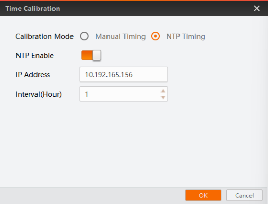
Figure 6-13 NTP Timing
NTP Enable
When this parameter is enabled, the camera time will be corrected according to the parameters you configure.
IP Address
The IP address of the NTP server.
Interval
The interval for correcting camera time.
Note
By default, the port number of the NTP server is 123 and it cannot be changed.
● Right-click a base used for matching a handhold code reader, and select BLE Pair Code to open the BLE Pair Code window, use the handhold code reader to scan the code to finish the match.
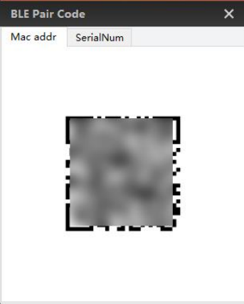
Figure 6-14 BLE Pair Code
Mac Address
A base can be matched with a 3 series handhold code reader via scanning the Mac address pair code.
SerialNom
A base can be matched with a 2 series handhold code reader via scanning the serial number.
Note
Only handheld code readers can match bases via BLE pair code.
6.2 Running Mode
The Software allows you to select different running modes for the code reader in different situations based on your requirements. For example, if you need to configure the code reader, you can set the running mode to test mode.
You can set the running mode on the upper-left of the live view window.
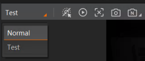
Figure 6-15 Running Mode
The following table shows the description of each running mode.
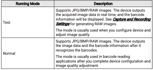
Note
The running mode may vary with the camera model and firmware version.
6.3 Code Reading Mode Settings
The device supports different code reading modes, including common mode, accurate mode, continuous mode, and batch mode.
Right click the device in Device Connection, and click Feature Tree. Go to Trigger and IO Control → Read Code Method, and select it according to actual demands.
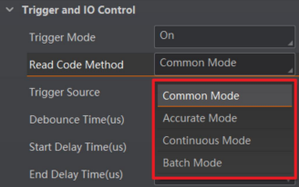
Figure 6-16 Code Reading Mode Settings
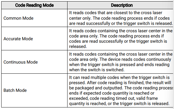
Note
These parameters are only supported by handheld code readers.
6.4 Device Control Settings
Go to Device Control, you can view battery value, temperature, and other information of the device and smart base.
This topic includes the following:
Note
● Only wireless handheld code readers support configuring smart base parameters.
● The specific parameters may differ by device models and firmware versions.
6.4.1 Device Parameters
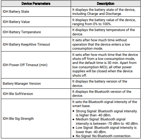
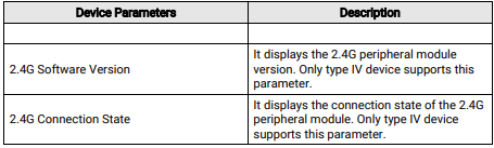
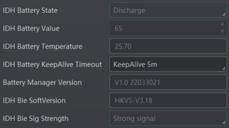
Figure 6-17 Device Parameters
6.4.2 Smart Base Parameters
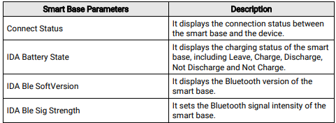
Strong Signal: Bluetooth signal intensity is higher than -40 dBm.Medium Signal: Bluetooth signal intensity is between -70 dBm to -40 dBm.Low Signal: Bluetooth signal intensity is lower than -40 dBm.No Signal: No Bluetooth connection.

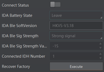
Figure 6-18 Smart Base Parameters
6.5 Image Settings
The Image Settings module allows you to configure image related features for the device. The basic features in the Image Settings module include features of the Image category and the Light category, which allow you to configure parameters such as exposure time, gain, gamma, and those related to the device light source. Besides the basic features, you may also configure features related to auto focus and self adapt, or both of them with the smart tune feature depending on the device support, as well as other features such as image flipping and the test pattern.You can also set ROIs if needed for image acquisition and auto focus respectively.
Click  Image Settings to open the Image Settings panel.
Note
The actual features displayed vary with the device model.
6.5.1 Image Features
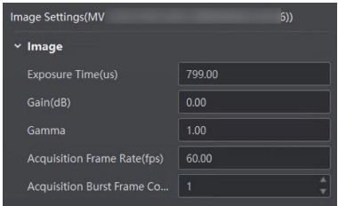
You can configureparameters including exposure time, gain, gamma, acquisition frame rate, and acquisition burst frame count in the Image feature based on your needs.
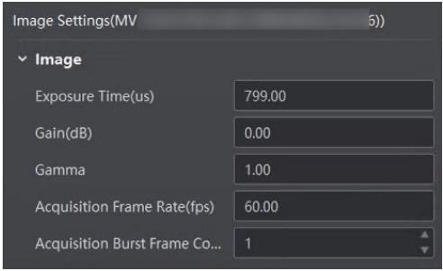
Figure 6-19 Image Settings
Note
The image features vary with different models of code readers.
Exposure Time
Increasing the exposure time will enhance the image brightness at the expense of lowering acquisition frame rate, and smear may occur when acquiring images of moving object.
Gain
Increasing Gain will enhance the image brightness at the expense of increasing noise.
Gamma
Decreasing Gamma will enhance the image contrast, which benefits code reading.
Acquisition Frame Rate
Determine the image number acquired by the device per second.
Acquisition Burst Frame Count
Determine the image number outputted by the device when triggered.
Note
For details about the valid range of the exposure time and Gain, and the maximum acquisition frame rate, see the device specification.
6.5.2 Set Polling
The polling function allows the camera to acquire images based on the parameters you set, including exposure time, gain, Gamma, light source, focus position, etc. Currently, 2 types of polling modes are available, including single mode and multiple mode.
Single Mode
The single mode allows the camera to acquire images based on one set of parameters you select.
Before You Start
● Make sure you have set the running mode to Normal mode. See Running Mode for details.
● Stopping the real-time acquisition is required before setting the polling function.
Steps
Note
● After polling is enabled, the device acquires images with its max. frame rate. Once the polling disabled, the frame rate you set in Acquisition Frame Rate takes effect.
● The polling function and specific parameters may differ by device model.
1. Go to Image Settings → Image, and set Polling Enable to Single.
2. Select one set of parameters (e.g., Param1) from Polling Param.
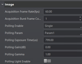
Figure 6-21 Set Polling Parameters (Single Mode)
3. Set Polling Exposure Time, Polling Gain, and Polling Gamma according to actual demands.
4. Optional: Enable Polling Light Enable according to actual demands.
5. Optional: Enable Polling Focus Enable, and set Polling Focus Pos and Polling Focus Temp according to actual demands.
Polling Focus Pos
It sets the focus position of the polling.
Polling Focus Temp
It displays the device's temporary position while setting the focus position.
6. Optional: Repeat the above steps to set polling parameters for other sets. You can also click  Polling Param on the control toolbar to set polling parameters for every set at once in a pop-up window.
Multiple Mode
The multiple mode allows the camera to acquire images based on multiple sets of parameters you select.
Before You Start
Stopping the real-time acquisition is required before setting the polling function.
Steps
Note
● In multiple mode, the camera supports trigger parameters like software trigger, external trigger, TCP, etc., but does not support stopping polling via the external trigger.
● The parameter of Best Polling Group Idx is used to display the polling parameter number when the camera recognizes codes after enabling polling. If the polling is disabled or polling parameters are edited, it displays 1 by default.
● The rule for multiple-mode polling is that the polling is started from the polling parameter with Best Polling Group Idx, and then execute other polling parameters you selected in turn. For example, if the Param3 is the Best Polling Group Idx and Param1, Param2, Param4 and Param5 are enabled, the polling order is Param3 > Param4 > Param5 > Param1 > Param2.
1. Go to Image Settings → Polling Enable, and select Multiple at the Polling Enable field.
2. Set Polling Time and Polling Period according to actual demands.
3. Select 2 to 8 sets of parameters (e.g. Param1 and Param2) from Polling Param, and enable Polling Param Enable to let them take effect.
4. Set Polling Exposure Time, Polling Gain, and Polling Gamma according to actual demands.
5. Optional: Enable Polling Lighting Enable according to actual demands.
6. Optional: Enable Polling Focus Enable, and set Polling Focus Pos and Polling Focus
Temp according to actual demands.
Polling Focus Pos
It sets the focus position of the polling.
Polling Focus Temp
It displays the device's temporary position while setting the focus position.
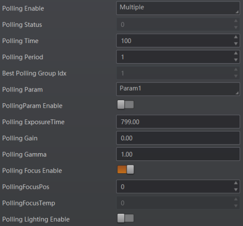
Figure 6-22 Multiple Mode
6.5.3 Light Features
You can set various parameters for the light used for acquiring code information to meet different needs, such as light type, light mode, lighting duration, etc.
Click Image Settings → Light to set the following parameters.
Light Type
Own Lighting
Use the device's embedded light source to light during code reading.
External Lighting
The device control the external light source by triggering output during code reading.
Non Lighting
The device turns off light source during code reading.
If you select Own Lighting, you can set the following features.
AmingLight Enable
If you enable it, you can put the to-be-read part of an object in the covering area of the aminglight, so that you can quickly specify the to-be-read region for the device. It should be supported by the device.
Lighting Enable
Switch it on to turn on the light of the device during code reading.
Note
This feature is only supported by devices with only one light source. For devices with more than one light, use Lighting Selector to control the status of their lights.
Lighting Selector
Select the LED light to light during code reading on the light panel, or click All On to light all lights.
Note
● This function should be supported by devices.
● The number of lights depends on device types.
Lighting Mode
● Flash Strobe: The light flashes at a specific interval.
● Strobe Long: The light is solid.
Lighting Duration
Set the duration (unit: μs) of each flash if you select Flash Strobe as the lighting mode.
Lighting Delay Time
The feature is available If you set Flash Long as the lighting mode. The feature determines the delay time (unit: μs) for lighting after exposure.
Lighting Ahead Time
The feature determines how earlier (unit: μs) the light source start lighting before exposure
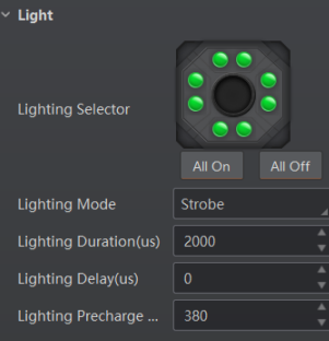
Figure 6-23 Own Lighting
If you select External Lighting, you can configure the following features.
Line Out Duration
The lighting duration of the external light source.
Line Out Delay Time
Set the delay time (unit: μs) for lighting after the device outputting event source information.
Line Out Ahead Time
Set how earlier (unit: μs) the external light start lighting ahead of the device outputting event source information.
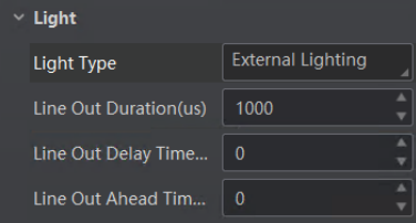
Figure 6-24 External Lighting
6.5.4 Image ROI
Image ROI defines the Region of Interest (ROI) for image acquisition. After setting the image ROI, the Software only acquires the image data within the ROI.
Before You Start
Start or stop acquisition to make sure that live view image is displayed. For details about acquisition and live view, see Acquisition and Live View for details.
Steps
Note
Image ROI should be supported by the device.
1. Click Image Settings → Image ROI to show the related parameters.
2. Draw ROI.
– Click Draw, and then drag the cursor on the image to draw ROI (displayed as a blue rectangle).
– Click Edit, and then the ROI (displayed as a blue rectangle) will cover the whole image.
Note
You can move the cursor to the edge of the rectangle, and then drag the appearing two-way arrow to adjust the ROI size
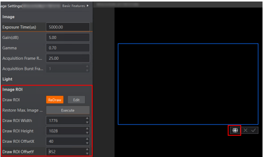 Figure 6-25 Image ROI
Optional: Adjust the position of the ROI.
– Click  to move the ROI to the center of the Live View window.
– Hover the cursor onto the ROI and then drag the ROI to adjust its position.
– Set ROI Width, ROI Height, ROI Offset X, ROI Offset Y to adjust the size or position of the ROI.
ROI Width
The pixel number on the horizontal direction.
ROI Height
The pixel number on the vertical direction.
ROI Offset X
Horizontal offset from the origin to the region of interest (in pixels).
ROI Offset Y
Vertical offset from the origin to the region of interest (in pixels).
4. Click  or right-click the image and then click Finish.
Only the image data within the selected ROI will be displayed.
Note
The image resolution will be lower after setting ROI.
5. Optional: Click Execute in the Restore Max. ROI field to restore the image to the origin. The image resolution will also be restored to the origin.
6.5.5 Smart Tune Control
With smart tune control, you can configure device parameters to read codes with better reading quality conveniently by starting auto focus and/or self adapt with one click. When the process is completed, the code reading result will show up in the History panel.
Note
● Make sure you have set the device running mode to Test mode. For details about running modes, see Running Mode.
● The smart tune feature requires device support and the parameters displayed vary with the device model. The actual interface shall prevail.
On the Image Settings panel, click SmartTuneControl to show the related parameters. Refer to the sections below respectively for how to configure device parameters via the device and the Software.
Configure Device Parameters via Device
If supported by the device, you can switch on Button Tune to enable configuring device parameters with buttons on the device. For details, refer to the user manual of the corresponding device.

Figure 6-26 Enable Button Tune
Configure Device Parameters via the Software
You can also configure device parameters via the Software.
SmartTune Start
Click Execute in this field to start the smart tuning process, i.e., start auto focus and/or self adapt depending on the device support. A window will pop up showing the current progress and the result when completed.
Note
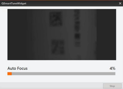
Figure 6-27 Smart Tune in Progress
● You can also click  on the toolbar at the top of the interface to start smart tuning.
● In the mid of the smart tuning process, you can click Stop on the bottom right of the window to end the process at any time.
● Click Save to polling library on the lower right of the Smart Tune window, select a polling library, and click Save to save the current parameter settings to the selected polling library.
● Some devices supports displaying the real-time smart tune image upon during the first time smart tune. Press the button again to close the image.
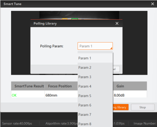
Figure 6-28 Smart Tune Completed
Stop Tune
If an individual auto focus or self adapt process is in progress at the moment, you can click Execute in this field to end them immediately.
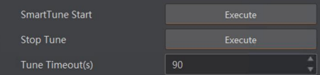
Figure 6-29 Smart Tune Features
Tune Timeout
Set the maximum time (unit: second) for tuning. It will stop once the time spent for tuning exceeds the set value.
Tune Status
Displays the current tuning progress. The number matches with the percentage displayed on the Smart Tune Widget window, and 100 indicates that tuning is completed.
Focus Param
If needed, you can set the focus related parameters and start auto focus independently.
Note
● You can also click on the toolbar at the top of the interface to start auto focus.
● The parameter configurations under Focus Param are similar to those for setting Auto Focus. Refer to Auto Focus for details about how to set the related parameters.
SelfAdapt Param
If needed, you can set the self-adapt related parameters and start self adapt independently.
Note
● You can also click on the toolbar at the top of the interface to start self adapt.
● The parameter configurations under SelfAdapt Param are similar to those for setting SelfAdapt Adjust. Refer to SelfAdapt Adjust for details about how to set the related parameters.
6.5.6 Auto Focus
You can set the focus of the code reader to match your code reading requirements. The Software supports focus on the whole image or on the ROI.
Note
● The function requires device support.
● Set the running mode to Test mode before setting focus and switch to Normal mode after auto focus is completed. For details about running modes, see Running Mode.
On the Image Settings panel, click Focus Param to show the related parameters.
Focus Mode
Click Execute to start auto focus based on the mode you select in Focus Mode Selector. If Whole Area Focus is selected, focus will be adjusted based on the whole image; if Roi Area Focus is selected, focus will be adjusted based on the set ROI.
Note
To start auto focus, you can also click Auto Focus on the control toolbar.
Focus Step
Set the focus step, which defines the distance for each focus increase or decrease.
Current Step
Displays the current focus position.
FocusPositive / FocusNegative Execute
Click Execute to increase/decrease the focus distance by the value set for Focus Step.
OriginalFocus Execute
Click Execute to return to the original focus (the Current Step will return to 0).
Focus Position
Select Position 1, Position 2, Position 3... or Position n for saving the current focus settings.
Focus Position Save
Click Execute to save the current focus settings to the position selected in Focus Position (e.g., Position 2).
Focus Position Load
Click Execute to load the position specified in Focus Position if you have saved focus settings to this position before.
Area Focus
If Roi Area Focus is selected as the focus mode, focus can be adjusted based on the ROIs drawn. You can click Draw in the Draw Focus ROI field to draw an ROI on the image. You can also set an ROI by editing the following parameters.
AFXROI
The x-coordinate of the upper-left point of the ROI.
AFYROI
The y-coordinate of the upper-left point of the ROI.
AFWidthROI
Width of the ROI.
AFHeightROI
Height of the ROI
6.5.7 SelfAdapt Adjust
By setting selfadapt parameters such as the adjust mode and the gain/exposure value, you can get a better code reading quality.
Before You Start
Make sure you have connected the device to the Software and have stopped acquisition.
Steps
Note
● The function requires device support.
● Set the running mode to Test mode and switch to Normal mode after selfadapt adjusting is completed. For details about running modes, see Running Mode.
1. On the Image Settings panel, click SelfAdapt Param.
2. Select an adjust mode.
High Quality
If you select this mode, exposure will be adjusted in priority. The acquired picture will have a smaller gain and noise, which makes a higher picture quality. It is suitable for objects with a slow moving speed.
High Speed
If you select this mode, gain will be adjusted in priority. There may be more noise on the picture. It is suitable for objects with a fast moving speed.
3. Select a parameter source.
Default Param
The device will adjust the default parameters predefined in the device.
Polling Param
The device will adjust the selected polling parameter.
4. Optional: Set the value for Gain Max and/or Exposure Max depending on the adjust mode you selected.
5. Select a code type mode from Code SelfAdapt, 1D Code, 2D Code, and Stack Code.
Code SelfAdapt
The device adaptively adds all code types within the field of view.
1D/ 2D/Stack Code
The device adaptively adds all 1D/2D/stack codes within the field of view.
6. Optional: Select a lighting mode from Light Adapt, All Light Enable, and All Light Disable.
Light Adapt
When the adjustment starts, all light combinations will be traversed, from which the most optimal group will be selected for light control.
7. Set the value for Adjust Timeout. When the time costed for selfadapt adjust exceeds the set value, selfadapt adjust will stop.
Note
This function should be supported by device.
8. Click Execute next to Adjust Start to apply the set parameters and start the selfadapt adjust.
Note
You can also click Self-Adapt Adjust on the control toolbar.
The result will be displayed in a pop-up window when the adjustment is completed.
6.5.8 Other Features
You can set other image related features, such as Reverse X (image flipping). On the Image Settings panel, click All Features on the upper-right to display all image related features (including Other Features).
Mirror X
Flip horizontally the image sent by the device. The feature is enabled by default.
Test Pattern
Select the pattern for image quality test. If image exception exists during acquisition, you can check if similar exception exists in the test to determine the reason of the exception.
Off
Image is coming from the sensor.
mono bar
Image is filled with stripes of white and black.
checkboard
Image is filled with checkboard.
oblique mono bar
Image is filled with oblique stripes of white and black.
Multiple Exposure Gain Polling Enable
Configure exposure and (or) gain for 4 consecutive images. After enabled, you can
configure exposure time and gain time for the acquisition of each one of the 4 images.
You can use this feature to enhance the brightness of the acquired images.
Note
The features vary with different devices.
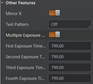 Figure 6-30 Other Features
6.6 Algorithm Settings
Algorithm Settings module allows you to define the types of the to-be-read barcodes, the region of interest for recognizing barcodes, the 1D code algorithm, the 2D code algorithm, and other barcode reading algorithm.
Click  Algorithm Settings to enter the Algorithm Settings module.
Note
The features vary with different devices.
6.6.1 Add Barcode
You can set the types and the maximum number of barcodes required to be read out. Three categories of barcodes are available, i.e., one-dimensional (1D) barcode, two-dimensional (2D) barcode, and stack code. 1D code (such as Code128, Code 39, or EAN) refers to the barcode representing data in the widths (lines) and the spacings of parallel lines. 2D code (such as QR code or DM code) refers to the barcode representing data in the small and individual dots contained in squares or rectangles. Stack code refers to the stacked linear barcode which combines the structure of 1D barcode with the data capacity of 2D barcode.
Steps
1. Click Algorithm Settings and expand Select Code if it is collapsed.
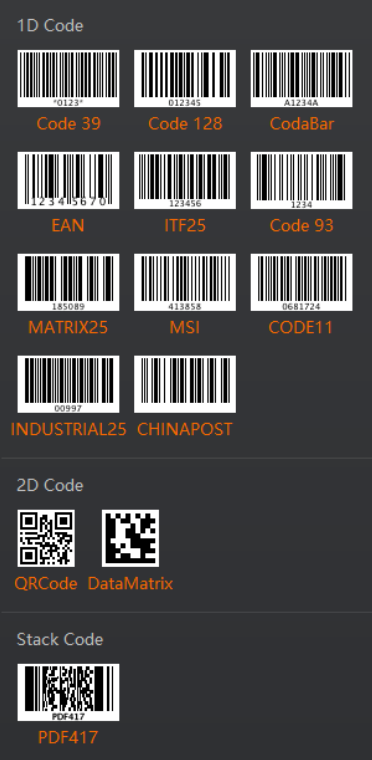
Figure 6-31 Select Code
2. Select one or multiple barcode types or click All in the upper-right corner. The frames of the selected barcode types turn to orange. Corresponding code types with numbers are displayed at the bottom.
Note
● The supported barcode types may vary with different devices.
● The more types you select, the more time will be consumed to recognize the codes in the image.
3. Set the maximum number of barcodes to be recognized in Number of 1D Code, Number of 2D Code, and Number of Stack Code respectively.
Note
The higher you set, the more time will be consumed to recognize the codes in the image.
6.6.2 Algorithm ROI
Algorithm ROI defines the Region of Interest (ROI) for recognizing codes on the basis of algorithm. After setting algorithm ROI, the device only recognizes codes within the ROI, which helps improve code reading efficiency.
Before You Start
Start acquisition and then stop it to make sure an image is displayed. For details about
acquisition and live view, see Acquisition and Live View.
Note
● The device should support algorithm ROI settings.
● The configurable parameters vary with different device models.
Steps
1. On the Algorithm Settings panel, click next to Algorithm ROI to show parameters related to setting the algorithm ROI.
2. Select a channel from Channel Selector if the device has multiple channels.
Note
● Skip this step if the device has only one channel.
● For some devices with initial rotating angle, the Software supports drawing the ROI after rotating the device.
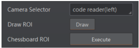
Figure 6-32 Channel Selector
3. Draw algorithm ROI.
● Click Draw, and then drag the cursor on the image to draw a new ROI (displayed as a green rectangle marked with sequence number).
Note
The supported number of ROI varies for different device types.
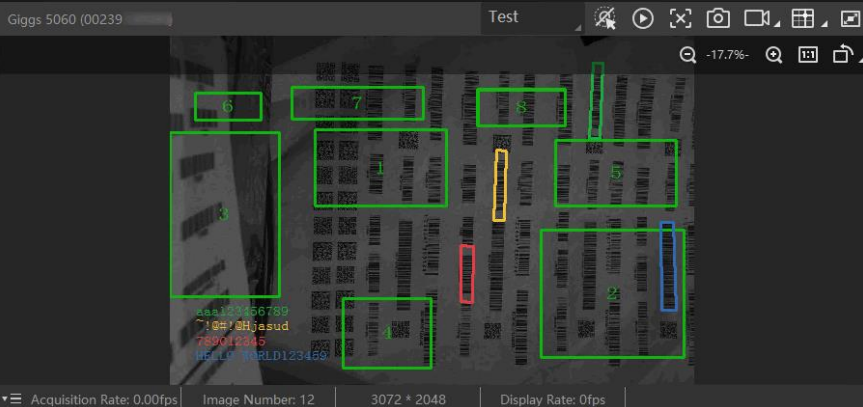 Figure 6-33 Multiple Algorithm ROI
● Click Batch, and then set the parameters on the Batch Create ROI window.
Area
Area refers to the region in the image inside which you draw multiple algorithm ROIs.
Area Offset
The offset of the area's top left vertex from the top left vertex of the image.
Area Size
Area refers to the region in the image inside which you draw multiple algorithm ROIs.
ROI Number
The width and height of the area.
Row Spacing
The distance between each row of ROI.
Column Spacing
The distance between each column of ROI.
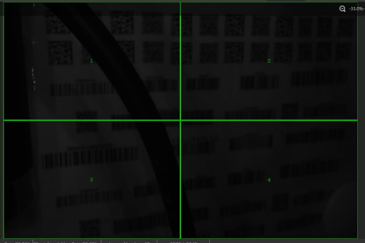
Figure 6-34 Algorithm ROIs Drawn In a Batch
The device only parses and recognizes codes within the ROIs.
4. Optional: Edit ROI.
| Operations | Description |
| Adjust ROI Position | Click an ROI to select it, or select an ROI from ROI Selector, and then drag the cursor (displayed as  ) to adjust the position of the ROI. ) to adjust the position of the ROI. |
| Adjust ROI Size | Click an ROI to select it, or select an ROI from ROI Selector, and then move the cursor (displayed as ) to the edge of the ROI until it turns into  or or  , and finally drag or to adjust the size of the ROI. , and finally drag or to adjust the size of the ROI. |
| Draw Chessboard ROI | Draw multiple ROIs which are like a Chessboard as a whole |
| Clear All ROIs | Click Clear All ROIs to clear all ROIs you drawn. |
| Restore Max. ROI | Click Execute beside Restore Max. Algorithm ROI to restore the algorithm ROI to its maximum size, which covers the whole original image. After that, the device will recognize and parse codes in the whole image. |
| Adjust ROI Position and Size Precisely | Select an ROI from ROI Selector, and then set values for ROI, Width, ROI Height, ROI Offset X, and ROI Offset Y to adjust the position and size of the ROI precisely |
| Enable/Disable ROI | Select an ROI from ROI Selector, and then turn on or off ROI Enable to enable or disable the ROI respectively |
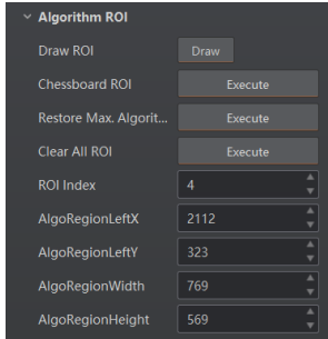
Figure 6-35 Algorithm ROI Settings
6.6.3 Set Algorithm Parameters
You can select at least one type of 1D code or 2D code to set parameters related to recognition algorithm for the 1D code or 2D code.
1D Code Algorithm
You can set the parameters related to the recognition algorithm for 1D codes.
Note
● Make sure you have selected at least one type of 1D code. For details about selecting code type, see Add Barcode.
● The parameters displayed vary with the device modeland firmware version.
● Some parameters should be configured in the feature tree. See Feature Tree
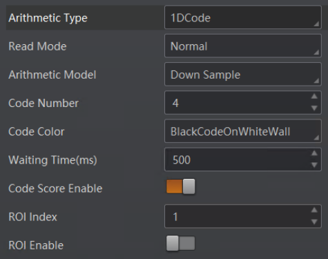
Figure 6-36 Features of the 1D Code
On the Algorithm Settings panel, click  next to Algorithm Parameter to show the algorithm related parameters. Select 1DCode from the drop-down list of Arithmetic Type. The following list introduces features related to 1D code algorithm.
Read Mode
Compared with Normal, Power is mainly used for reading codes with low quality. So the code reading in Power mode may cost more time. It is recommended to use the default value.
Code Number
The maximum number of codes that can be read.
Timeout Value (Waiting Time)
The maximum running time (unit: ms) of an algorithm. The code reader will stop parsing images and return results if the running time exceeds the configured value.
Code Color
Select the code color type that can be recognized by the device.
BlackCodeOnWhiteWall
If the code is black bars on a white background, it can be recognized by the device.
WhiteCodeOnBlackWall
If the code is white bars on a black background, it can be recognized by the device.
Adaptive
The device can recognize both types of codes mentioned above. However, the reading time will be longer compared with the above two modes.
Code39 Check
Enable this to verify code 39.
ITF25 Check
Enable this to verify code ITF25.
1D Code Quality Enable
If you enable this, code quality rating will work during the acquisition, and the overall grade will be displayed in the History pane. See Set Code Quality Evaluation.
Code Score Enable
If you enable this, the Software can give the scores of the codes it has read.
ROI Index
Display the No. of current ROI.
ROI Enable
If you enable this, you can adjust the position and size of the ROI.
2D Code Algorithm
You can set the parameters related to the recognition algorithm for 2D codes.
Note
● Make sure you have selected at least one type of 2D code. For details about selecting code type, see Add Barcode.
● The parameters displayed vary with the device model and firmware version.
● Some parameters should be configured in the feature tree. See Feature Tree.
On the Algorithm Settings panel, click next to Algorithm Parameter to show the algorithm related parameters. Select 2DCode from the drop-down list of Arithmetic Type. The following list introduces features related to 2D code algorithm.
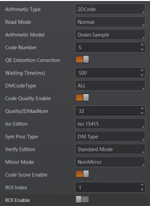
Figure 6-37 Features of the 2D Code
Read Mode
Compared with Normal, Power is mainly used for reading codes with low quality. So the code reading in Power mode may cost more time. It is recommended to use the default value.
Code Number
The maximum number of codes that can be read.
QR Distortion Correction
Enable this if the QR code is printed on a bottle or the QR code is creased.
Timeout Value (Waiting Time)
The maximum running time (unit: ms) of an algorithm. The code reader will stop parsing images and return results if the running time exceeds the configured value.
DM Code Type
Select the version of DM codes that can be recognized by the device from ALL, ECC140, and ECC200
Code Quality Enable
Enable code quality rating. After you enable this function, you can see the overall grade (DM code only) and code score in reading history.
Note
When the device is in Test mode, code quality rating is enabled by default and cannot be disabled. You can configure code quality rating when the device is in Normal mode.
ISO Edition
ISO 15415 is suitable for continuous code; ISO 29158 is suitable for dot code.
Mirror Mode
Turn on the mode only when the acquired images is mirror images (mirroring in X coordinate).
After configuring the above parameters, you can start acquisition and see the overall grade and code score in reading history. For details about reading history, see View Reading History.
Code Score Enable
After you enable this function, you can see the code score in reading history.
ROI Index
Display the No. of current ROI.
ROI Enable
If you enable this, you can adjust the position and size of the ROI.
Stack Code Algorithm
You can set algorithm parameters for stack codes according to actual needs.
Note
● Make sure you have selected type PDF417 in Add Barcode. For details, refer to Add Barcode.
● For different models and firmware versions of the device, the specific parameters may differ, and the actual parameters displayed shall prevail.
● Some parameters should be configured in the feature tree. See Feature Tree.
On the Algorithm Settings panel, click next to Algorithm Parameter to show the algorithm related parameters. Select StackCode from the drop-down list of Arithmetic Type.
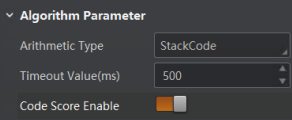
Figure 6-38 Features of the Stack Code
Read Mode
Compared with Normal, Power is mainly used for reading codes with low quality. So the code reading in Power mode may cost more time. It is recommended to use the default value.
Code Number
The maximum number of codes that can be read.
Timeout Value (Waiting Time)
The maximum running time (unit: ms) of an algorithm. The code reader will stop parsing images and return results if the running time exceeds the configured value.
Code Score Enable
If you enable this, the Software can give the scores of the codes it has read.
ROI Index
Display the No. of current ROI.
ROI Enable
If you enable this, you can adjust the position and size of the ROI
6.6.4 Set Code Quality Evaluation
You can set parameters for evaluating the quality of 1D and 2D codes.
Steps
Note
When the device is in Test mode, code quality rating is enabled by default and cannot be disabled. You can configure code quality rating when the device is in Normal mode.
1. On the Algorithm Settings panel, click  next to Algorithm Parameter to show the algorithm related parameters.
2. Enable 1D Code Quality Enable or 2D Code Quality Enable for 1D and 2D code algorithms respectively.
3. Set the corresponding parameters for code quality rating.
– If 1DCode is selected for Arithmetic Type, you can set specific values for different code quality levels of parameters such as decodability, symbol contrast, modulation, minimum reflectance, minimum edge contrast, defects, and aperture, and decide whether to include edge determination, decode, and quiet zone for code quality rating.
– If 2DCode is selected for Arithmetic Type, you can set the following parameters:
● ISO Edition: Select the rating standard from ISO 15415 and ISO 29158. ISO 15415 is suitable for continuous code; ISO 29158 is suitable for dot code.
● Verify Edition: Select the rating mode from Standard Mode and HIK ModeNEU Mode.
What to do next
After configuring the above parameters, you can start acquisition and view the overall grade in the History panel. For details about viewing reading history, see View Reading History.
6.6.5 Set Code Score
You can enable the Code Score function so that the Software can give the scores of the codes it has read.
Steps
Note
● This function may differ by device models.
● In Test mode, this function is enabled by default. In Normal mode, you need to enable it manually.
● The score of a code is determined by two factors which are the image quality and print quality of codes. A score is between 0 and 100, and the higher the score, the easier the code can be read.
1. Right click the device in Device Connection panel, and click Feature Tree.
2. Go to Algorithm Control, and switch on Code Score Enable.
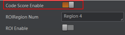
Figure 6-39 Enable Code Score
3. Click  to start acquisition, and the Software will display specific code score in the history area.
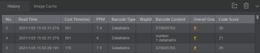 Figure 6-40 Code Score
4. Optional: Go to Image Settings, and adjust parameters such as the exposure time, gain, Gamma, and light source if the code score is low.
Note
The code may have poor printing quality if its score is still low after parameter adjustment.
6.6.6 Enable Waybill Cutout
The Software provides the Waybill Cutout functionality, which can automatically cut out the waybill image from the waybill area recognized by the code reader, and save the cut-out waybill image.
Before You Start
● Make sure you have set the running mode of the code reader to Normal. For details about setting running mode, see Running Mode.
● For ID6000 series code readers, you should also have set the value of Billinfo parameter to True in the feature tree to enable the device to recognize the waybill area from the acquired images. For details about feature tree, see Feature Tree.
Steps
Note
● The device should support the functionality.
● You can set the saving path and naming rule for the cut-out waybill picture. For details, see Capture and Recording Settings.
1. On the Algorithm Settings panel, click All Features on the upper-right to display all algorithm related features (including waybill cutout).
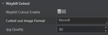 Figure 6-41 Waybill Cutout Settings
2. Set the parameters.
Waybill Cutout Enable
If turned on, the waybill image will be cut out from the acquired images and be saved to the saving path you defined.
Cutted-out Image Format
Set the format (Mono8, JPG, or BMP) of the cut-out waybill image.
JPG Quality
Set the quality of the cut-out waybill image if you select JPG as its format. The larger the value, the better the image quality. The waybill area will be recognized in the images during code reading (see the picture below) and the waybill image will be saved to the saving path you set.
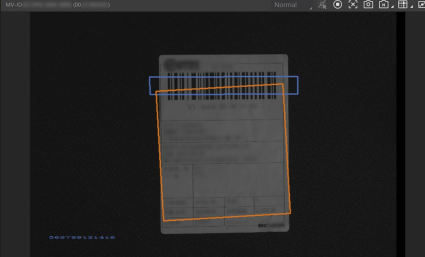
Figure 6-42 Waybill Live View
6.7 I/O Control Settings
The IO Control Settings section allows you to set the features related to the control of the input and output signals of devices.
6.7.1 Input
In the Input section, you can switch the trigger mode to on and set the related parameters so that the device will only acquire image data when the specified trigger source is activated.
Before You Start
Connect a device to the Software.
Steps
Note
The parameters displayed vary with the device model.
1. Click  I/O Control Settings to enter the I/O Control Settings panel.
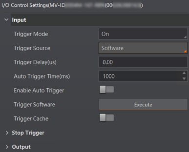
Figure 6-43 I/O Control Settings
2. Set the Trigger Mode to On.
Note
You should stop acquisition before you can set the trigger mode. For details about acquisition, see Acquisition and Live View.
3. In the Trigger Delay field, specify the delay in microseconds (us) to be applied after the trigger reception before activating it.
4. Select a source type from the drop-down list of Trigger Source as the trigger source, and then set the corresponding features.
● Software: Specify that the trigger source will be generated by the Software using the Trigger Software command.
○ Auto Trigger Time: Specify the interval in milliseconds (ms) to activate the trigger automatically.
○ Enable Auto Trigger: If enabled, the Software will generate trigger source automatically according to the configured auto trigger time.
○ Trigger Software: Click Execute to manually generate a trigger source.
Note
The feature is available only when Enable Auto Trigger is disabled or that the configured auto trigger is already generated.
● LineIn 0/1/2: Specify which physical line (or pin) and associated input control block to be used as the external source for the trigger signal.
○ Debounce Time: Specify the time in microseconds (us) to ignore any change of state of a signal after the signal's initial rising edge. In other words, if the duration of a signal is shorter than the specified debounce time, the signal will be regarded as invalid. You can set debounce time to avoid false triggers due to environmental disturbance (e.g., electromagnetic interference) or device exceptions.
○ Trigger Activation: Specify the activation mode of the trigger.
› Rising Edge: Specify that the trigger is considered valid on the rising edge of the source signal.
› Falling Edge: Specify that the trigger is considered valid on the falling edge of the source signal.
› Level High: Specify that the trigger is considered valid if the level of the source signal is high.
› Level Low: Specify that the trigger is considered valid if the level of the source signal is low.
● Counter 0: Specify the counter as the internal source for the trigger signal.
○ Count Number: Specify that the trigger source will be generated after the set number of valid signals appear. For example, if you set the Count Number to 3, the trigger source will be generated after 3 signals appear.
Note
For descriptions about other features after selecting Counter 0 as the trigger source, see the preceding text.
● TCP/UDP Start: Specify the TCP/UDP server as the source for the trigger signal. When the server receives the specified trigger text, the trigger signal will be outputted.
Note
○ For some device models, you can select the text format from the drop-down list of TCP/UDP Trigger Text Format.
› If Str is selected, enter the text in string format in the box next to TCP/UDP Start Trigger Text.
› If Hex is selected, enter the text in hexadecimal format in the box below TCP/UDP Trigger Start String. If needed, you can click to open the ASCII Cross Reference Table and click a table cell to add the corresponding content to the text box.
○ You may also configure the corresponding string text for sending a TCP/UDP handshake request and receiving a TCP/UDP handshake response via Trigger and IO Control on the feature tree.
● Serial Start: Specify the serial port as the source for the trigger signal. When the serial port receives the specified trigger text, the trigger signal will be outputted.
Note
For some device models, you can select the text format from the drop-down list of Serial Trigger Text Format.
○ If Str is selected, enter the text in string format in the box next to Serial Start Trigger Text.
○ If Hex is selected, enter the text in hexadecimal format in the box below Serial Trigger Start String. If needed, you can click to open the ASCII Cross Reference Table and click a table cell to add the corresponding content to the text box.
● Self Trigger: Specify the trigger period (i.e., interval) in milliseconds (ms) and the total trigger count. The device will generate trigger signals itself accordingly during acquisition.
● USB Start: Specify the USB port as the source for the trigger signal.
● Response Trigger: When the brightness of the field of view changes, code reading and barcode output are automatically triggered. The device monitors the change of image brightness value in real time and starts code reading when the change exceeds the configured sensitivity threshold.
Note
Only handheld code readers support Self Trigger and Response Trigger.
5. Optional: Configure the source and condition to stop a trigger.
Note
Refer to Stop Trigger for details.
6.7.2 Stop Trigger