
9. Tool Application
The Software provides multiples tools for the management, configuration, and maintenance of cameras, such as IP Configurator (for editing camera IP addresses), Log Collection Tool (for collecting camera logs), Virtual Camera (for testing reading results), etc.
9.1 IP Configurator
The online GigE Vision cameras in the same local subnet with the PC on which the Software runs will be enumerated in the device list. You can configure the IP addresses and other network parameters of these cameras.
Note
You can move the cursor to GigE and then click  to manually refresh the cameras.
You can view the camera status on the Status column of the device list. If the camera status is free or unreachable, you can edit its network parameters including IP address.
Free
The camera is available and you can edit its IP address.
In Use
The Software or other processes are accessing the camera. You need to stop the live view and disconnect the camera, or terminate other processes to access the camera.
Unreachable
The camera is unreachable due to one of the following two reasons:
● The network of the camera is abnormal. Check the camera network settings.
● The camera is on the same subnet with the PC on which the Software runs, but NOT in the same network segment. You should modify its IP address to the same network segment with the PC to make the camera available for connection and use.
You can also click  to select camera information (model name, device user ID, status, etc.). The selected item will be displayed on the camera list.
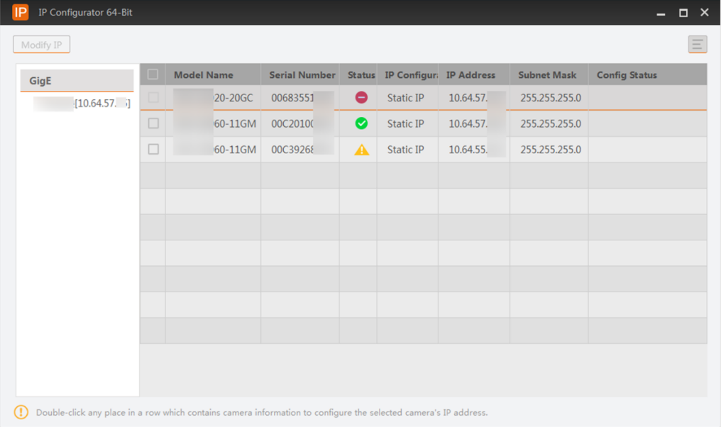
Figure 9-1 IP Configurator
9.1.1 Edit IP Address of a Single Camera
You can modify the IP address of a single camera if the camera status is Free or Unreachable
Steps
1. Select a network interface.
2. Double-click any place in the camera row to open the Modify IP Address window.
3. Select the Static IP, DHCP, or LLA as the IP type.
Note
You can change the IP type only when the camera status is Free. And if you change the IP type, the camera will be reset to its power up state.
Static IP
For setting the IP type as Static IP, you can modify the IP address, subnet mask, and default gateway.
DHCP
The camera is set to automatically obtain an IP address. This means that the IP address will dynamically change (within a range) every time the camera or computer is restarted.
Note
● If the IP addresses of your PC and camera are both static but they are not in the same IP segment, you need to change the camera IP address to a dynamic IP address.
● If you enter restricted IP types including D type (from 224 to 239), E type (from 240 to 254), the IP addresses starting with 127 or 255, or IP addresses with incorrect IP address formats, you will not be able to access the devices.
LLA
The camera uses a default IP address from the link-local address block. Link-local addresses for IPv4 are defined in the address block 169.254.0.0/16 in CIDR notation. In IPv6, they are assigned the address block fe80::/10.
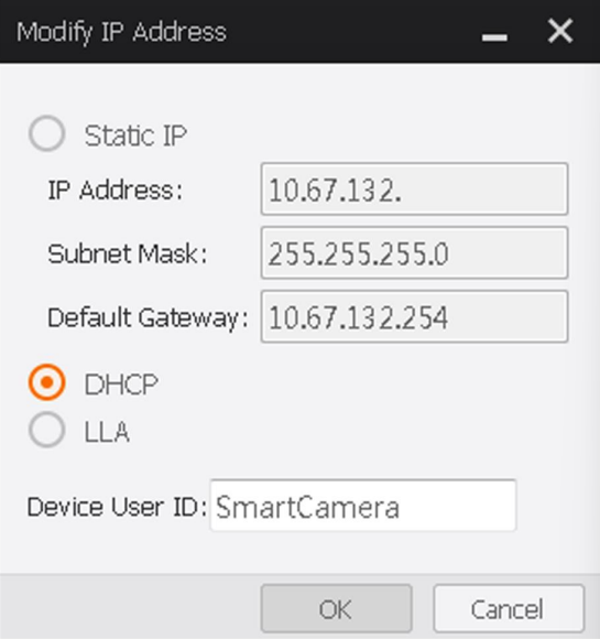
Figure 9-2 Modify IP Address
4. Optional: Edit the camera name in Device User ID field.
5. Click OK to save the settings.
Note
If the modified IP address conflicts with another device's IP address in the same local subnet, a prompt will pop up to remind you that IP conflict occurs. Change the IP address in this situation.
9.1.2 Edit IP Addresses of Multiple Cameras
You can batch modify the IP addresses of multiple cameras under the same interface.
Steps
1. Select a network interface.
2. Select the cameras to be modified.
Note
You can select up to 20 cameras.
3. Click Modify IP to open the Batch Modify IP window.
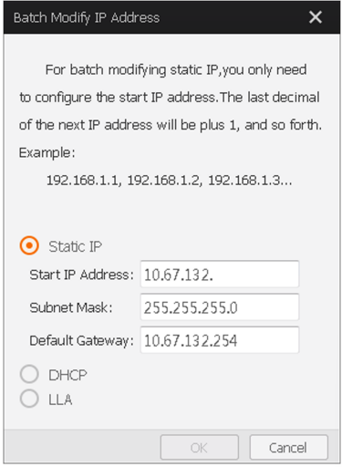
Figure 9-3 Batch Modify IP Addresses
4. Select Static IP, DHCP, or LLA as the IP type.
Note
● For setting the IP type as Static IP, you can set the start IP address, subnet mask, and default gateway.
● For batch modifying static IP, you only need to configure the start IP address. The last decimal of the next IP address will be plus 1, and so forth (example: 192.168.1.1, 192.168.1.2, 192.168.1.3...).
5. Click OK to save the settings.
Note
If the modified IP address conflicts with another device's IP address in the same local subnet, a prompt will pop up to remind you that IP conflict occurs. Change the IP address in this situation.
9.2 File Access
You can batch import a feature configuration file from the local PC to multiple devices. The File Access tool supports importing an mfa file containing the feature configuration information from the local PC to multiple devices in a batch. See details in Import Feature
9.3 Firmware Updater
You can update the firmwares of the cameras or frame grabbers via the Firmware Updater tool.
Steps
Note
● Cameras of different types of interfaces cannot be updated at the same time.
● The firmware update file should match the camera model.
1. Open the Firmware Updater window.
– Click Tool → Firmware Updater on the main page.Open Firmware_Updater in the installation folder.
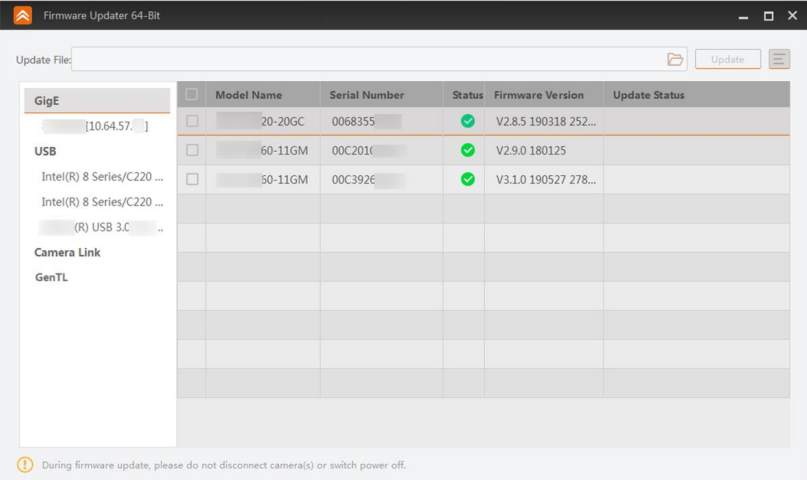 Figure 9-4 Firmware Updater
2. Optional: The device information will be displayed on the window. You can conduct the following operations as needed.
GigE and USB Interfaces
● Select GigE or USB, and the devices connected to it will be displayed on the right.
● Select an interface under GigE or USB, and the cameras connected to the interface will be displayed on the right.
● The tool will auto refresh the cameras by default. You can also click on the right of GigE and USB to manually enumerate the cameras.
Camera Link Interfaces
● Select Camera Link, and the devices connected to the camera link will be displayed on the right.
● Select an interface under Camera Link, and the cameras connected to the camera link will be displayed on the right.
● The tool will not auto refresh the devices connected to camera link by default. You need to click on the right of Camera Link to manually enumerate the cameras.
GenTL Interfaces
Right-click GenTL and click Select CTI File. Select and open a CTI file, and the tool will enumerate the frame grabbers and cameras in the CTI file.
● Select GentTL, and all the frame grabbers in the CTI file will be displayed on the right.
● Select a frame grabber under GentTL, and the cameras connected to the frame grabber will be displayed on the right.
● Select a camera under GentTL, and the cameras connected to all the frame grabbers will be displayed on the right.
● The tool will not auto refresh the frame grabbers and cameras connected by the GenTL by default. You need to click  on the right of GenTL to manually enumerate the cameras.
3. Optional: Click  to select the to-be-displayed device information (model name, MAC address, firmware version, etc.).
4. Select cameras or frame grabbers to be updated.
Note
No more than 20 cameras or frame grabbers can be selected.
5. Click  to select an update file (DAV format) in the local PC.
The matched cameras will be selected automatically.
6. Click Update.
Note
● During the update, do not break the connection between the devices and the PC, and ensure that the devices are working.
● The devices will restart automatically upon finishing the update.
● The update of frame grabbers will take effect after restarting the PC
9.4 Import/Export Features
On the Import/Export Features window, all GigE Vision cameras on the same local subnet with the PC on which the Software runs will be displayed automatically. You can select camera(s) and then export their feature configurations to the local PC as MFS files or import MFS files to batch load the feature configurations to the camera(s). For example, if you need to import a single feature of user set 1 to multiple devices, you will need to use the tool.
Steps
1. Open the Import/Export Features window in one of the following two ways.
– Click Tool → Import/Export Features.
– Double-click Import_Export_Features in the installation directory of the Software.
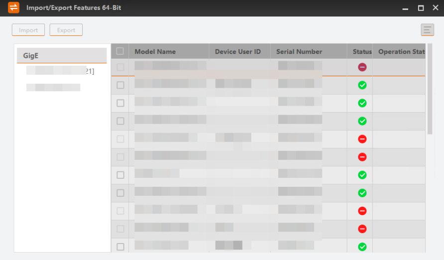
Figure 9-5 Import/Export Feature Window
2. Click to select the to-be-displayed information (model name, device user ID, MAC address, etc.).
Note
● Up to 20 devices can be selected.
● You can only select the devices in Free status.
3. Export or import the features of the selected devices.
● Click Export to export the features of the selected devices as an MFS file.
Note
The exported MFS file is named as "device model_serial number" by default. Example: MV-ID5060M-08S-WBN_00F45884701.mfs.
● Click Import to select an MFS file so as to import the features saved in the file to the selected cameras.
Note
● The progress and results of the operation are displayed on the Operation Status column.
● You can view the exception information and error code if importing features to a specific camera fails.
9.5 FTP Server
You can configure server parameters for transmitting data between devices and the server via FTP protocol.
Note
● Make sure the service port is not occupied, you have the permission for operating the target path, and there is enough space in the target path.
● Make sure you have the permission to operate the saving path and the saving path has enough storage.
Go to Settings → FTP Service. The Software will read the service port, user name, and password automatically. Click  and set the saving path. Click OK to save the settings.
Note
Only if you enable the service can the Software store data to the saving path.
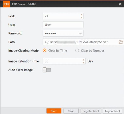
Figure 9-6 FTP Service
Note
After being enabled, the FTP server will run in the background, and will not be stopped after quitting the Software. It can be minimized in the task list.
Port
The host's port number of FTP server.
User
The user name of the FTP server.
Password
The password for logging in the FTP server.
Path
Click  to set the saving path of transmitted files.
Image-Clearing Mode
Clear by Time
The images will be cleared when the image retention time ends.
Clear by Number
The server will clear images when the image number exceeds the Image Save Frame you set.
Auto-Clear Image
After this parameter is enabled, when the image number exceeds the Image Save Frame you set, or the storing time exceeds the image retention time you set, the images will be automatically cleared.
Note
The port, user name, and password you entered here should be the same with those you configured on the Communication Settings page.
You can start or stop the FTP server and set its auto-launch function via the pop-up window.
Start
Click Start on the lower right of the pop-up window to start the FTP server.
Close
Click Close on the lower right of the pop-up window to stop running the FTP server.
Register boot
Click Register boot on the lower right of the pop-up window to automatically launch the FTP server when the PC is power-on.
Logout boot
Click Logout boot on the lower right of the pop-up window to disable the auto-launch of the FTP server.
9.6 Log Collection Tool
This tool is used for collecting logs on the device.
Steps
1. Click Tool → Log Collection Tool to open the saving location of HIKTerm Terminal.
2. In the Tools window, unzip the HIKTerm.zip file.
3. Open the folder named HIKTerm, open the folder named Terminal, and double-click the Terminal.exe to run the program.
Note
For details about how to use this tool, contact the technical support.
With this tool, you can simulate code reading environment with local images, which helps test reading results thereby determining the optimal algorithm settings for your code reading applications.
Before You Start
Make sure the dongle of MVID-M series has been plugged in, or the tool will be unavailable.
Steps
1. Click Tool → Reading Training Tool to open the tool window.
2. Click  to upload local barcode images to the tool.
Note
● The barcode images should be in the format of JPG or BMP.
● Up to 20 barcode images can be uploaded.
3. Click  to start reading the uploaded local images automatically (the images will be automatically switched per second).
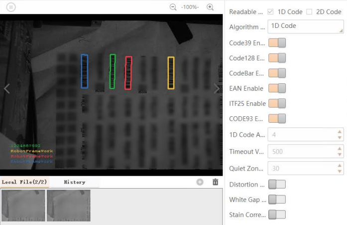
Figure 9-7 Virtual Code Reader
4. Set the parameters of the barcode reading algorithm on the right, such as readable code type, timeout value, quiet zone width, etc.
Readable Code Type
Select 1D code or 2D code as the readable code type.
Algorithm Type
Select the algorithm for reading 1D code or 2D code, and different parameters will be displayed accordingly.
Note
For details about 1D code algorithm parameters, see 1D Code Algorithm. For details about 2D code algorithm parameters, see 2D Code Algorithm.
5. Optional: Perform the following operations if required.
 or
or  to zoom in or zoom out the image respectively
Manually Control Code Reading
Click
to zoom in or zoom out the image respectively
Manually Control Code Reading
Click  to stop auto-reading and then click
  or
or  to manually switch images for code reading.
Delete an Image
Hover the cursor onto a thumbnail of an image and then click
to manually switch images for code reading.
Delete an Image
Hover the cursor onto a thumbnail of an image and then click  to delete it.
Delete All Images
Click
to delete it.
Delete All Images
Click  to delete all the uploaded local images.
View Read History
Click History to view the code reading history of the Virtual Code Reader. You can view the information including read time, cost time, PPM, barcode type, and barcode content.
to delete all the uploaded local images.
View Read History
Click History to view the code reading history of the Virtual Code Reader. You can view the information including read time, cost time, PPM, barcode type, and barcode content.● Read Time: The time when the barcode is read.
● Cost Time: The algorithm processing time cost to recognize the information contained in the barcode. Export Read History Click History and then click
 to export the code reading history of the Virtual Code Reader as a CSV or xlsx file to the local PC
9.8 Virtual Camera
Virtual Camera is a tool designed for scenarios where constructing a real setup of code reading environment is not feasible. It can simulate cameras and generate virtual cameras, in order to help simplify tests during development stage.
Steps
1. Click Tool → Virtual Camera to open the Virtual Camera window.
2. On the left side of the Virtual Camera window, select the camera(s) you want to simulate.
Note
You can select multiple cameras at a time.
3. Click Collect to start collecting the data of the camera(s).
The simulated camera(s) will appear on the drop-down virtual camera list on the right side of the tool window.
4. Select the camera from the drop-down list, and click Add.
5. On the Device Connection panel on the main window, refresh the device list to enumerate the added virtual camera(s).
6. Optional: On the Virtual Camera window, right-click a virtual camera and click Delete to delete the virtual camera.
9.9 Driver Installation Tool
The Driver Manager can manage the drivers needed by the Software. Double click Driver_Installation_Tool in the installation folder. The drivers' installation status will be detected automatically and you can select to install or uninstall the related drivers
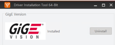
Figure 9-8 Driver Installation Tool
9.10 NIC Configurator
NIC Configurator allows you to configure properties for the network interface cards. For details about how to configure properties of the network interface cards, see Environment Configuration.